Example: Building a Four-Level Hierarchy of Schedulers
This section provides a more complete example of building a 4-level hierarchy of schedulers. The configuration parameters are shown in Figure 1. The queues are shown at the top of the figure with the other three levels of the hierarchy below.
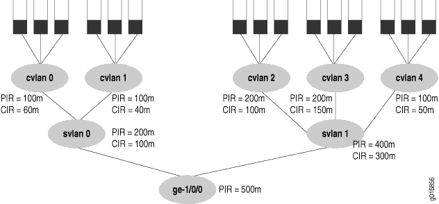
The figure’s PIR values are configured as the shaping
rates and the CIRs are configured as the guaranteed rate on the Ethernet
interface ge-1/0/0. The PIR can be oversubscribed (that
is, the sum of the children PIRs can exceed the parent’s, as
in svlan 1, where 200 + 200 + 100 exceeds the parent rate
of 400)). However, the sum of the children node level’s CIRs
must never exceed the parent node’s CIR, as shown in all the
service VLANs (otherwise, the guaranteed rate could never be provided
in all cases).
This configuration example presents all details of the CoS configuration
for the interface in the figure (ge-1/0/0), including:
Configuring the Interface Sets
[edit interfaces]
interface-set svlan-0 {
    interface ge-1/0/0 {
        unit 0;
        unit 1;
    }
}
interface-set svlan-1 {
    interface ge-1/0/0 {
        unit 2;
        unit 3;
        unit 4;
    }
}
Configuring the Interfaces
The keyword to configure hierarchical schedulers is at the physical interface level, as is VLAN tagging and the VLAN IDs. In this example, the interface sets are defined by logical interfaces (units) and not outer VLAN tags. All VLAN tags in this example are customer VLAN tags.
[edit interface ge-1/0/0]
hierarchical-scheduler;
vlan-tagging;
unit 0 {
    vlan-id 100;
}
unit 1 {
    vlan-id 101;
}
unit 2 {
    vlan-id 102;
}
unit 3 {
    vlan-id 103;
}
unit 4 {
    vlan-id 104;
}
Configuring the Traffic Control Profiles
The traffic control profiles hold parameters for levels above the queue level of the scheduler hierarchy. This section defines traffic control profiles for both the service VLAN level (logical interfaces) and the customer VLAN (VLAN tag) level.
[edit class-of-service traffic-control-profiles]
tcp-500m-shaping-rate {
    shaping-rate 500m;
}
tcp-svlan0 {
    shaping-rate 200m;
    guaranteed-rate 100m;
    delay-buffer-rate 300m; # This parameter is not shown in the figure.
}
tcp-svlan1 {
    shaping-rate 400m;
    guaranteed-rate 300m;
    delay-buffer-rate 100m; # This parameter is not shown in the figure.
}
tcp-cvlan0 {
    shaping-rate 100m;
    guaranteed-rate 60m;
    scheduler-map tcp-map-cvlan0; # Applies scheduler maps to customer VLANs.
}
tcp-cvlan1 {
    shaping-rate 100m;
    guaranteed-rate 40m;
    scheduler-map tcp-map-cvlan1; # Applies scheduler maps to customer VLANs.
}
tcp-cvlan2 {
    shaping-rate 200m;
    guaranteed-rate 100m;
    scheduler-map tcp-map-cvlanx; # Applies scheduler maps to customer VLANs.
}
tcp-cvlan3 {
    shaping-rate 200m;
    guaranteed-rate 150m;
    scheduler-map tcp-map-cvlanx; # Applies scheduler maps to customer VLANs
}
tcp-cvlan4 {
    shaping-rate 100m;
    guaranteed-rate 50m;
    scheduler-map tcp-map-cvlanx; # Applies scheduler maps to customer VLANs
}
Configuring the Schedulers
The schedulers hold the information about the queues, the last level of the hierarchy. Note the consistent naming schemes applied to repetitive elements in all parts of this example.
[edit class-of-service schedulers]
sched-cvlan0-qx {
    priority low;
    transmit-rate 20m;
    buffer-size temporal 100ms;
    drop-profile loss-priority low dp-low;
    drop-profile loss-priority high dp-high;
}
sched-cvlan1-q0 {
    priority high;
    transmit-rate 20m;
    buffer-size percent 40;
    drop-profile loss-priority low dp-low;
    drop-profile loss-priority high dp-high;
}
sched-cvlanx-qx {
    transmit-rate percent 30;
    buffer-size percent 30;
    drop-profile loss-priority low dp-low;
    drop-profile loss-priority high dp-high;
}
sched-cvlan1-qx {
    transmit-rate 10m;
    buffer-size temporal 100ms;
    drop-profile loss-priority low dp-low;
    drop-profile loss-priority high dp-high;
}
Configuring the Drop Profiles
This section configures the drop profiles for the example. For more information about interpolated drop profiles, see RED Drop Profiles for Congestion Management.
[edit class-of-service drop-profiles]
dp-low {
    interpolate fill-level 80 drop-probability 80;
    interpolate fill-level 100 drop-probability 100;
}
dp-high {
    interpolate fill-level 60 drop-probability 80;
    interpolate fill-level 80 drop-probability 100;
}
Configuring the Scheduler Maps
This section configures the scheduler maps for the example. Each one references a scheduler configured in Configuring the Schedulers.
[edit class-of-service scheduler-maps]
tcp-map-cvlan0 {
    forwarding-class voice scheduler sched-cvlan0-qx;
    forwarding-class video scheduler sched-cvlan0-qx;
    forwarding-class data scheduler sched-cvlan0-qx;
}
tcp-map-cvlan1 {
    forwarding-class voice scheduler sched-cvlan1-q0;
    forwarding-class video scheduler sched-cvlan1-qx;
    forwarding-class data scheduler sched-cvlan1-qx;
}
tcp-map-cvlanx {
    forwarding-class voice scheduler sched-cvlanx-qx;
    forwarding-class video scheduler sched-cvlanx-qx;
    forwarding-class data scheduler sched-cvlanx-qx;
}
Applying the Traffic Control Profiles
This section applies the traffic control profiles to the proper levels of the hierarchy.
Although a shaping rate can be applied directly to the physical interface, hierarchical schedulers must use a traffic control profile to hold this parameter.
[edit class-of-service interfaces]
ge-1/0/0 {
    output-traffic-control-profile tcp-500m-shaping-rate;
    unit 0 {
        output-traffic-control-profile tcp-cvlan0;
    }
    unit 1 {
        output-traffic-control-profile tcp-cvlan1;
    }
    unit 2 {
        output-traffic-control-profile tcp-cvlan2;
    }
    unit 3 {
        output-traffic-control-profile tcp-cvlan3;
    }
    unit 4 {
        output-traffic-control-profile tcp-cvlan4;
    }
}
interface-set svlan0 {
    output-traffic-control-profile tcp-svlan0;
}
interface-set svlan1 {
    output-traffic-control-profile tcp-svlan1;
}
You should be careful when using a show interfaces queue command that references nonexistent class-of-service logical interfaces.
When multiple logical interfaces (units) are not configured under
the same interface set or physical interface, but are referenced by
a command such as show interfaces queue ge-10/0/1.12 forwarding-class
be or show interfaces queue ge-10/0/1.13 forwarding-class
be (where logical units 12 and 13 are not configured as a class-of-service
interfaces), these interfaces display the same traffic statistics
for each logical interface. In other words, even if there is no traffic
passing through a particular unconfigured logical interface, as long
as one or more of the other unconfigured logical interfaces under
the same interface set or physical interface is passing traffic, this
particular logical interface displays statistics counters showing
the total amount of traffic passed through all other unconfigured
logical interfaces together.