ON THIS PAGE
Example: Maintaining a Constant Traffic Flow by Configuring a Static VLAN Interface with a Dynamic Profile for Subscriber Access
This example shows how to configure a static VLAN interface with a dynamic profile using static schedulers and CoS parameters for subscriber access to maintain a constant traffic flow. The CoS parameters configure a best-effort data service for subscribers.
Requirements
Before you begin, be sure that your environment meets the following requirements:
The interface is hosted on an MX Series router.
For hierarchical scheduling configurations, hierarchical scheduling is enabled in the static CLI for the interface referenced in the dynamic profile. If not, the dynamic profile fails.
Only one traffic-control-profile is configured under a dynamic profile.
The output-traffic-control-profile that binds the traffic-control profile to the interface is defined within the same dynamic profile as the interface.
Overview
In a dynamic profile, you can configure VLAN subscriber interfaces over the following statically created logical interface types:
GE—Gigabit Ethernet
XE—10-Gigabit Ethernet
AE—Aggregated Ethernet
Topology
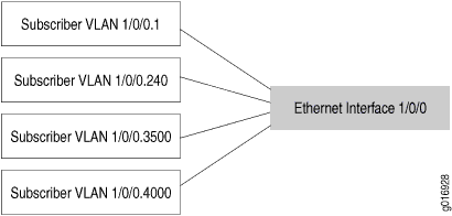
We recommend that you configure each subscriber on a statically created VLAN.
Figure 1 shows an example of subscriber interfaces on an individual VLAN.
You can further separate VLANs on subscriber interfaces by configuring a VLAN interface as the underlying interface for a set of IP demux interfaces.
Configuration
To configure a static VLAN interface with a dynamic profile for subscriber access, perform these tasks:
- CLI Quick Configuration
- Configuring a Subscriber Interface with a Static VLAN
- Associating the Dynamic Profile with a Statically Created Interface
- Configuring the Firewall Filter
- Configuring Static Schedulers in a Dynamic Profile
- Associating the Scheduler with a Scheduler Map
- Configuring and Applying Static Traffic Shaping and Scheduling Parameters in a Dynamic Profile
CLI Quick Configuration
To quickly configure this example, copy the following
configuration commands into a text file, remove any line breaks, and
then paste the commands into the CLI at the [edit] hierarchy
level.
set interfaces ge-2/2/0
set interfaces ge-2/2/0 hierarchical-scheduler
set interfaces ge-2/2/0 vlan-tagging
set interfaces ge-2/2/0 vlan-tagging unit 100 vlan-id 100
set interfaces ge-2/2/0 vlan-tagging unit 100 vlan-id 100 family inet
set interfaces ge-2/2/0 vlan-tagging unit 100 vlan-id 100 family inet unnumbered-address lo0.0 preferred-source-address 10.0.0.1
set dynamic-profiles data-service
set dynamic-profiles data-service interfaces $junos-interface-ifd-name
set dynamic-profiles data-service interfaces $junos-interface-ifd-name unit $junos-underlying-interface-unit
set dynamic-profiles data-service interfaces $junos-interface-ifd-name unit $junos-underlying-interface-unit family inet
set dynamic-profiles data-service firewall family inet filter filter EF_limit_G=768K
set dynamic-profiles data-service firewall family inet filter filter EF_limit_G=768K term EF
set dynamic-profiles data-service firewall family inet filter filter EF_limit_G=768K term default
set dynamic-profiles data-service firewall family inet filter filter EF_limit_G=768K term EF from forwarding-class EF
set dynamic-profiles data-service firewall family inet filter filter EF_limit_G=768K term EF then policer POL_EF_G=768K
set dynamic-profiles data-service firewall family inet filter filter EF_limit_G=768K term default then accept
set dynamic-profiles data-service class-of-service schedulers be-scheduler
set dynamic-profiles data-service class-of-service schedulers be-scheduler buffer-size remainder
set dynamic-profiles data-service class-of-service schedulers be-scheduler drop-profile-map loss-priority any protocol any
set dynamic-profiles data-service class-of-service schedulers be-scheduler drop-profile-map loss-priority any protocol any drop-profile drop3
set dynamic-profiles data-service class-of-service schedulers be-scheduler priority low
user@host# set dynamic-profiles data-service class-of-service schedulers be-scheduler transmit-rate percent 40
set dynamic-profiles data-service class-of-service schedulers be-scheduler excess-rate percent 90
set dynamic-profiles data-service class-of-service schedulers be-scheduler excess-priority high
set dynamic-profiles data-service class-of-service scheduler-maps data-service-map
set dynamic-profiles data-service class-of-service scheduler-maps data-service-map forwarding-class best-effort
set dynamic-profiles data-service class-of-service scheduler-maps data-service-map forwarding-class best-effort scheduler be-scheduler
set dynamic-profiles data-service class-of-service traffic-control-profiles tcp-data-service
set dynamic-profiles data-service class-of-service traffic-control-profiles tcp-data-service scheduler-map data-service-map
set dynamic-profiles data-service class-of-service traffic-control-profiles tcp-data-service shaping-rate 50k
set dynamic-profiles data-service class-of-service traffic-control-profiles tcp-data-service guaranteed-rate 10k
set dynamic-profiles data-service class-of-service traffic-control-profiles tcp-data-service delay-buffer-rate 10k
set dynamic-profiles data-service class-of-service interfaces $junos-interface-ifd-name unit $junos-underlying-interface-unit output-traffic-control-profile tcp-data-service
Configuring a Subscriber Interface with a Static VLAN
Step-by-Step Procedure
After you configure a static VLAN interface, you can reference it in a dynamic profile.
Configure the static VLAN interface.
[edit]
user@host# set interfaces ge-2/2/0
Enable hierarchical scheduling for the interface.
[edit interfaces ge-2/2/0]
user@host# set hierarchical-scheduler
Enable VLAN tagging.
[edit interfaces ge-2/2/0]
user@host# set vlan-tagging
Configure the unit and assign a VLAN ID.
[edit interfaces ge-2/2/0 vlan-tagging]
user@host# set unit 100 vlan-id 100
Define the family address type (inet for IPv4) for the VLAN interface.
[edit interfaces ge-2/2/0 vlan-tagging unit 100 vlan-id 100]
user@host# set family inet
Enable the physical interface to borrow an IP address from the loopback interface by setting an unnumbered interface address. Configure a secondary IP address on the loopback interface, lo0.0, and configure it as the preferred source address.
[edit interfaces ge-2/2/0 vlan-tagging unit 100 vlan-id 100 family inet]
user@host# set unnumbered-address lo0.0 preferred-source-address 10.0.0.1
Results
Confirm the configuration of the static VLAN interface
by entering the show interfaces configuration command.
If the command output does not display the intended configuration,
repeat the instructions in this procedure to correct the configuration.
[edit]
user@host# show interfaces
interfaces {
    ge-2/2/0 {
        hierarchical-scheduler;
        vlan-tagging;
        unit 100 {
            vlan-id 100;
            family inet {
                unnumbered-address lo0.0 preferred-source-address 10.0.0.1;
            }
        }
    }
}
Associating the Dynamic Profile with a Statically Created Interface
Step-by-Step Procedure
A dynamic profile is a set of characteristics, defined
in a type of template, that you can use to provide dynamic subscriber
access and services for broadband applications. When configuring the
interface at the [dynamic-profiles profile-name interfaces] hierarchy level for a dynamic profile, you use
variables to specify the interface name and the logical unit value.
When a DHCP subscriber sends a DHCP request to the interface, the
dynamic profile replaces the interface name variable and logical unit
name variable with the actual interface name and logical unit number
of the interface that received the DHCP request.
Configuration of the interface name variable and logical
interface name variable at the [edit dynamic-profiles profile-name interfaces] hierarchy level is required
for a dynamic profile to function.
Create the new dynamic profile for data services for subscribers.
[edit]
user@host# set dynamic-profiles data-service
Define the
interface-namevariable statement with the internal $junos-interface-ifd-name variable used by the router to match the interface name of the receiving interface.[edit dynamic-profiles data-service] user@host# set interfaces $junos-interface-ifd-name
Define the
unitstatement with the internal variable.When referencing an existing interface, specify the $junos-underlying-interface-unit variable used by the router to match the unit value of the receiving interface.
When creating dynamic interfaces, specify the $junos-interface-unit variable used by the router to generate a unit value for the interface.
[edit dynamic-profiles data-service interfaces $junos-interface-ifd-name]
user@host# set unit $junos-underlying-interface-unit
or
[edit dynamic-profiles data-service interfaces $junos-interface-ifd-name]
user@host# set unit $junos-interface-unit
Define the family address type (inet for IPv4) for the $junos-interface-unit variable.
[edit dynamic-profiles data-service interfaces $junos-interface-ifd-name unit $junos-underlying-interface-unit]
user@host# set family inet
Results
Confirm the configuration of the dynamic profile by entering
the show dynamic-profiles configuration command. If the
command output does not display the intended configuration, repeat
the instructions in this procedure to correct the configuration.
[edit]
user@host# show dynamic-profiles
dynamic-profiles {
    data-service {
        interfaces {
            $junos-interface-ifd-name {
                unit $junos-underlying-interface-unit {
                    family inet;
                }
            }
        }
    }
}
Configuring the Firewall Filter
Step-by-Step Procedure
To configure a static VLAN interface with a dynamic profile for subscriber access, you can configure a firewall filter to provide enhanced security by blocking packets based on various match criteria, such as subjecting traffic to a policer for rate limiting, assigning the traffic to a class-of-service (CoS) forwarding class for later queuing and packet rewrite operations, or directing traffic to a specific routing instance.
Configure the family address type (inet for IPv4) for the firewall filter and specify the filter name.
We recommend that you name the filter something that indicates the filter’s purpose. In this example, we use the bandwidth limit settings.
[edit dynamic-profiles data-service]
user@host# set firewall family inet filter EF_limit_G=768K
Specify the term names for the filter. Make each term name unique and represent what its function is. The first term matches traffic that has been classified into the Expedited Forwarding (EF) class, and the second term matches all non-EF traffic.
[edit dynamic-profiles data-service firewall family inet filter EF_limit_G=768K]
user@host# set term EF
user@host# set term default
In each firewall filter term, specify the conditions used to match components of a packet. Configure the first term to match all traffic classified as EF class.
[edit dynamic-profiles data-service firewall family inet filter EF_limit_G=768K term EF]
user@host# set from forwarding-class EF
Specify the actions to take when the packet matches the condition in the first term. Send the EF traffic to the policer named POL_EF_G=768K.
[edit dynamic-profiles data-service firewall family inet filter EF_limit_G=768K term EF]
user@host# set then policer POL_EF_G=768K
Specify the action to take when the packet matches the condition in the second term. All non-EF packet traffic is accepted.
[edit dynamic-profiles data-service firewall family inet filter EF_limit_G=768K term default]
user@host# set then accept
Results
Confirm the configuration by entering the show dynamic-profiles
data-service firewall configuration command. If the command
output does not display the intended configuration, repeat the instructions
in this procedure to correct the configuration.
[edit]
user@host# show dynamic-profiles data-service firewall
family inet {
    filter  EF_limit_G=768K {
        term EF {
            from {
                forwarding-class EF;
            }
            then policer POL_EF_G=768K;
        }
        term default {
            then accept;
        }
    }
}
Configuring Static Schedulers in a Dynamic Profile
Step-by-Step Procedure
You can configure static scheduling and queuing parameters in a dynamic profile for subscriber access. Schedulers are part of the basic class-of-service (CoS) infrastructure. You must define at least one scheduler per forwarding class. Schedulers indicate a forwarding class’s priority, transmit weight, and buffer size, as well as various shaping and rate control mechanisms.
Specify the best-effort scheduler for which you want to configure parameters.
[edit dynamic-profiles data-service class-of-service]
user@host# set schedulers be-scheduler
Note:Set
schedulersto the name of the scheduler to be configured or to the Junos OS predefined variable ($junos-cos-scheduler) used for dynamic subscriber interfaces. The predefined variable is replaced with the scheduler name obtained from the RADIUS server when a subscriber authenticates over the interface to which the dynamic profile is attached.(Optional) Configure the buffer size to use the remaining buffer available.
This parameter allows you to specify an explicit buffer size, either as a percent of interface speed or as a function of time (specified in microseconds).
[edit dynamic-profiles data-service class-of-service schedulers be-scheduler]
user@host# set buffer-size remainder
(Optional) Configure the drop-profile map to associate one or more drop profiles with a queue.
The default random early detection (RED) drop profile is used when no explicit drop profile mapping is specified. Specify a packet-loss priority (PLP) level of any, and for the specified scheduler to accept any protocol type.
[edit dynamic-profiles data-service class-of-service schedulers be-scheduler]
user@host# set drop-profile-map loss-priority any protocol any
(Optional) Configure the drop profile to map a fill level (fullness of a queue) to a drop probability (probability that a packet is dropped).
[edit dynamic-profiles data-service class-of-service schedulers be-scheduler drop-profile-map loss-priority any protocol any]
user@host# set drop-profile drop3
You enable RED by applying a drop profile to a scheduler.
(Optional) Configure the queue’s scheduler priority to a specific level (low) for guaranteed rate traffic.
[edit dynamic-profiles data-service class-of-service schedulers be-scheduler]
user@host# set priority low
(Optional) Configure the queue’s transmit weight [in bits per second (bps)] or as a percentage of transmission capacity.
[edit dynamic-profiles data-service class-of-service schedulers be-scheduler]
user@host# set transmit-rate percent 40
The transmit rate guarantees the rate for the queue, assuming no priority-based starvation occurs. When you do not specify a transmit weight, or when the transmit rate is reached, the queue can only send excess-rate traffic because that queue’s priority is demoted to the excess region. A percentage of zero (0) drops all packets in the queue.
(Optional) Configure the queue’s weight as either a percentage, or a proportion, for any unused bandwidth traffic to share.
[edit dynamic-profiles data-service class-of-service schedulers be-scheduler]
user@host# set excess-rate percent 90
Behavior varies based on interface mode, explicit configuration, and whether any other queues have explicit weight configured. By default, excess bandwidth between the guaranteed and shaped rate is shared equally among queues.
(Optional) Configure the priority of how excess bandwidth traffic is sent on a scheduler in a dynamic profile.
[edit dynamic-profiles data-service class-of-service schedulers be-scheduler]
user@host# set excess-priority high
To prevent the queue from sending any excess rate traffic, set to none.
Results
Confirm the configuration of the scheduler with static
values in the dynamic profile by entering the show dynamic-profiles
data-service class-of-service configuration command. If the
command output does not display the intended configuration, repeat
the instructions in this procedure to correct the configuration.
[edit]
user@host# show dynamic-profiles data-service class-of-service
class-of-service {
    schedulers {
        be-scheduler {
            buffer-size remainder;
            drop-profile-map loss-priority any protocol any drop-profile drop3;
            priority low;
            transmit-rate percent 40;
            excess-rate percent 90;
            excess-priority high;
        }
    }
}
Associating the Scheduler with a Scheduler Map
Step-by-Step Procedure
After you define your schedulers, you must link them to a set of queues on a logical interface using a scheduler map. Applying a scheduler map to an interface places the related set of schedulers and drop profiles into effect.
Configure the scheduler map name.
[edit dynamic-profiles data-service class-of-service]
user@host# set scheduler-maps data-service-map
Configure a forwarding class to associate a scheduler with a scheduler map.
[edit dynamic-profiles data-service class-of-service scheduler-maps data-service-map]
user@host# set forwarding-class best-effort
Associate the scheduler you previously defined (be-scheduler) with the scheduler map.
[edit dynamic-profiles data-service class-of-service scheduler-maps data-service-map forwarding-class best-effort]
user@host# set scheduler be-scheduler
Results
Confirm the configuration of the scheduler map by entering
the show dynamic-profiles data-service class-of-service scheduler-maps configuration command. If the command output does not display the
intended configuration, repeat the instructions in this procedure
to correct the configuration.
[edit]
user@host# show dynamic-profiles data-service class-of-service scheduler-maps
scheduler-maps {
    data-service-map {
        forwarding-class best-effort scheduler be-scheduler;
    }
}
Configuring and Applying Static Traffic Shaping and Scheduling Parameters in a Dynamic Profile
Step-by-Step Procedure
Configure static traffic shaping and scheduling parameters in a traffic-control profile. A traffic-control profile is a generic class-of-service (CoS) container that you can apply at all points of a CoS hierarchy to affect the committed information rate (CIR), peak information rate (PIR), and excess bandwidth handling. You can specify the traffic-control profile at the port, logical interface, or logical interface-set level. The traffic-control profile also references the scheduler map.
Create the traffic-control profile and assign it a name.
[edit dynamic-profiles data-service class-of-service]
user@host# edit traffic-control-profiles tcp-data-service
Apply the static scheduler map, data-service-map, that you previously configured.
[edit dynamic-profiles data-service class-of-service traffic-control-profiles tcp-data-service]
user@host# set scheduler-map data-service-map
Configure the shaping rate [in bits per second (bps)] to use for the scheduler in the dynamic profile.
[edit dynamic-profiles data-service class-of-service traffic-control-profiles tcp-data-service]
user@host# set shaping-rate 50k
The shaping rate places a maximum limit on a queue’s transmit capacity. By default, the shaping rate is equal to the interface speed/shaping rate enabling the queue to send a the full rate of the interface.
Configure the guaranteed rate [in bits per second (bps)] to use for the scheduler in the dynamic profile.
[edit dynamic-profiles data-service class-of-service traffic-control-profiles tcp-data-service]
user@host# set guaranteed-rate 10k
The guaranteed rate is the minimum bandwidth the queue can receive; if excess physical interface bandwidth is available for use, the logical interface can receive more than the guaranteed rate provisioned for the interface, depending on how you choose to manage excess bandwidth and the interface’s mode of PIR compared to CIR/PIR.
Configure the delay-buffer rate [in bits per second (bps)] based on the delay-buffer calculation.
[edit dynamic-profiles data-service class-of-service traffic-control-profiles tcp-data-service]
user@host# set delay-buffer-rate 10k
The delay buffer rate setting at one level of the hierarchy becomes the reference bandwidth used at the next higher level, and the sum of the reference bandwidth cannot exceed the value used at a lower level. If you do not include this statement, the delay-buffer rate is based on the guaranteed rate if one is configured, or on the shaping rate if no guaranteed rate is configured.
After you configure the traffic shaping and scheduling CoS parameters in a dynamic profile, you apply them to an interface. The output traffic-control profile enables you to provide traffic scheduling to the interface.
Configure the interface name and logical interface using a variable, and apply the output traffic-control profile to the interface. Specify the previously defined traffic-control profile, tcp-data-service.
[edit dynamic-profiles data-service class-of-service]
user@host# set interfaces $junos-interface-ifd-name unit $junos-underlying-interface-unit output-traffic-control-profile tcp-data-service
Results
Confirm the configuration and application of the static
traffic shaping and scheduling parameters by entering the show
dynamic-profiles configuration command. If the command output
does not display the intended configuration, repeat the instructions
in this procedure to correct the configuration.
[edit]
user@host# show dynamic-profiles
dynamic-profiles {
    data-service {
        class-of-service {
            interfaces {
                $junos-interface-ifd-name {
                    unit $junos-underlying-interface-unit {
                        output-traffic-control-profile tcp-data-service;
                    }
                }
            }
            traffic-control-profiles {
                tcp-data-service {
                    scheduler-map data-service-map;
                    shaping-rate 50k;
                    guaranteed-rate 10k;
                    delay-buffer-rate 10k;
                }
            }
        }
    }
}
Verification
Confirm that the configuration is working properly.
- Verifying Traffic Shaping and Scheduling Profiles for Subscriber Access
- Verifying the Mapping of Schedulers for Subscriber Access
Verifying Traffic Shaping and Scheduling Profiles for Subscriber Access
Purpose
View the class-of-service (CoS) configurations that are referenced in a dynamic profile for subscriber access.
Action
user@host> show class-of-service traffic-control-profile
Traffic control profile: tcp-data-service, Index: 57625
  Shaping rate: 50000
  Scheduler map: data-service-map
  Delay Buffer rate: 10000
  Guaranteed rate: 10000
Meaning
The Shaping rate, Delay Buffer rate, and Guaranteed rate fields indicate rates of 50,000 bps, 10,000 bps, and 10,000 bps, respectively, for the traffic-control profile.
Verifying the Mapping of Schedulers for Subscriber Access
Purpose
Display the mapping of schedulers to forwarding classes and a summary of scheduler parameters for each entry.
Action
user@host> show class-of-service scheduler-map
Scheduler map: data-service-map, Index: 84

  Scheduler: be-scheduler, Index: 8721, Forwarding class:  best-effort
   Transmit rate: 40 percent, Rate Limit: none, Maximum buffer delay: 39 ms,
   Priority: low
   Drop profiles:
    Loss priority   Protocol    Index    Name
     Any            Any         8724     drop3
Meaning
The Scheduler map field indicates the parameters are for the best-effort scheduler. The Transmit rate field shows 40 percent; the Rate Limit field indicates no limit; and the Drop profiles fields are for drop3.