Example: Configuring CoS on EX Series Switches
Configure class of service (CoS) on your switch to manage traffic so that when the network experiences congestion and delay, critical applications are protected. Using CoS, you can divide traffic on your switch into classes and provide various levels of throughput and packet loss. This is especially important for traffic that is sensitive to jitter and delay, such as voice traffic.
This example shows how to configure CoS on a single EX Series switch in the network.
Requirements
This example uses the following hardware and software components:
-
EX Series switches
-
Any supported Junos OS release
Overview and Topology
This example uses the topology shown in Figure 1.
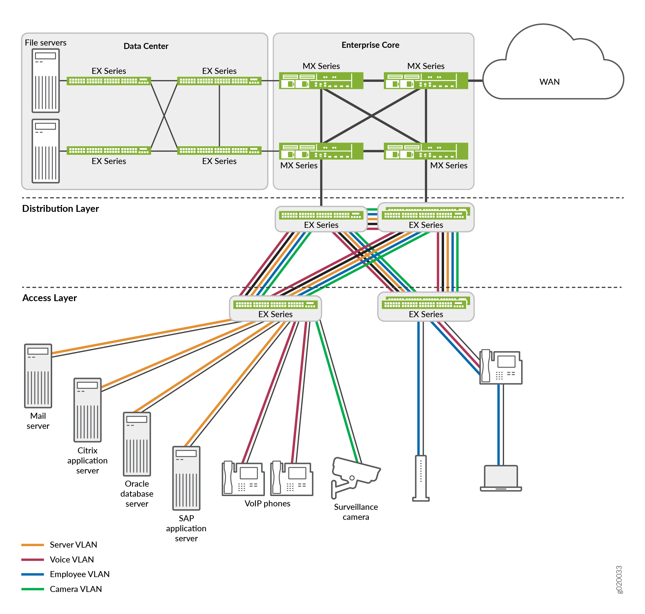
The topology for this configuration example consists of EX switches at the access layer.
The EX Series access switches are configured to support VLAN membership. On the
access layer switch, interfaces ge-0/0/0 and
ge-0/0/1 are assigned to the voice VLAN
(voice-vlan) for two VoIP IP phones. Switch interface
ge-0/0/2 is assigned to the camera VLAN
(camera-vlan) for the surveillance camera. Switch interfaces
ge-0/0/3, ge-0/0/4, ge-0/0/5,
and ge-0/0/6 are assigned to the server VLAN
(server-vlan) for the servers hosting various applications such
as those provided by Citrix, Microsoft, Oracle, and SAP. The trunk ports, ge-0/0/20
and ge-0/0/21, are assigned to the server, voice, employee, and camera VLANs and
used as uplink ports to connect the distribution layer switches.
Table 1 shows the VLAN configuration components.
|
VLAN Name |
VLAN ID |
VLAN Subnet and Available IP Addresses |
VLAN Description |
|---|---|---|---|
|
|
|
|
Voice VLAN used for employee VoIP communication. |
|
|
|
|
VLAN for the surveillance cameras. |
|
|
|
|
VLAN for the servers hosting enterprise applications. |
PoE-capable ports on EX Series switches support Power over Ethernet (PoE) to provide both network connectivity and power for VoIP telephones connecting to the ports. Table 2 shows the switch interfaces that are assigned to the VLANs and the IP addresses for devices connected to the switch ports on a 48-port switch, all ports of which are PoE-capable.
|
Interfaces |
VLAN Membership |
IP Addresses |
Port Devices |
|---|---|---|---|
|
|
|
|
Two VoIP telephones. |
|
|
|
|
Surveillance camera. |
|
|
|
|
Four servers hosting applications such as those provided by Citrix, Microsoft, Oracle, and SAP. |
This example shows how to configure CoS on a standalone EX Series switch. This example does not consider across-the-network applications of CoS in which you might implement different configurations on ingress and egress switches to provide differentiated treatment to different classes across a set of nodes in a network.
Although you will sometimes see schedulers configured for strict-high priority with a transmit-rate configured, that configuration is misleading because strict-high priority schedulers get unlimited bandwidth and the transmit-rate parameter has no effect on them. With this configuration, lower priority queues can suffer starvation if there is congestion. It is better that schedulers with strict-high priority have shaping-rate parameters configured, which is the correct way to limit their bandwidth.
Configuration
Procedure
CLI Quick Configuration
To quickly configure CoS, copy the following commands and paste them into the switch terminal window:
[edit]
set class-of-service forwarding-classes class app queue-num 5
set class-of-service forwarding-classes class mail queue-num 1
set class-of-service forwarding-classes class db queue-num 2
set class-of-service forwarding-classes class erp queue-num 3
set class-of-service forwarding-classes class video queue-num 4
set class-of-service forwarding-classes class best-effort queue-num 0
set class-of-service forwarding-classes class voice queue-num 6
set class-of-service forwarding-classes class network-control queue-num 7
set firewall family ethernet-switching filter voip_class term voip from source-address 192.168.1.1/28
set firewall family ethernet-switching filter voip_class term voip from source-address 192.168.1.2/28
set firewall family ethernet-switching filter voip_class term voip from protocol udp
set firewall family ethernet-switching filter voip_class term voip from source-port 2698
set firewall family ethernet-switching filter voip_class term voip then forwarding-class voice loss-priority low
set firewall family ethernet-switching filter voip_class term network_control from precedence [net-control internet-control]
set firewall family ethernet-switching filter voip_class term network_control then forwarding-class network-control loss-priority low
set firewall family ethernet-switching filter voip_class term best_effort_traffic then forwarding-class best-effort loss-priority low
set interfaces ge-0/0/0 description phone1–voip-ingress-port
set interfaces ge-0/0/0 unit 0 family ethernet-switching filter input voip_class
set class-of-service interfaces ge-0/0/0 shaping-rate 100m
set interfaces ge-0/0/1 description phone2–voip-ingress-port
set interfaces ge-0/0/1 unit 0 family ethernet-switching filter input voip_class
set firewall family ethernet-switching filter video_class term video from source-address 192.168.1.17/28
set firewall family ethernet-switching filter video_class term video from protocol udp
set firewall family ethernet-switching filter video_class term video from source-port 2979
set firewall family ethernet-switching filter video_class term video then forwarding-class video loss-priority low
set firewall family ethernet-switching filter video_class term network_control from precedence [net-control internet-control]
set firewall family ethernet-switching filter video_class term network_control then forwarding-class network-control loss-priority low
set firewall family ethernet-switching filter video_class term best_effort_traffic then forwarding-class best-effort loss-priority low
set interfaces ge-0/0/2 description video-ingress-port
set interfaces ge-0/0/2 unit 0 family ethernet-switching filter input video_class
set firewall family ethernet-switching filter app_class term app from source-address 192.168.1.33/28
set firewall family ethernet-switching filter app_class term app from protocol tcp
set firewall family ethernet-switching filter app_class term app from source-port [1494 2512 2513 2598 2897]
set firewall family ethernet-switching filter app_class term app then forwarding-class app loss-priority low
set firewall family ethernet-switching filter app_class term mail from source-address 192.168.1.34/28
set firewall family ethernet-switching filter app_class term mail from protocol tcp
set firewall family ethernet-switching filter app_class term mail from source-port [25 143 389 691 993 3268 3269]
set firewall family ethernet-switching filter app_class term mail then forwarding-class mail loss-priority low
set firewall family ethernet-switching filter app_class term db from source-address 192.168.1.35/28
set firewall family ethernet-switching filter app_class term db from protocol tcp
set firewall family ethernet-switching filter app_class term db from source-port [1521 1525 1527 1571 1810 2481]
set firewall family ethernet-switching filter app_class term db then forwarding-class db loss-priority low
set firewall family ethernet-switching filter app_class term erp from source-address 192.168.1.36/28
set firewall family ethernet-switching filter app_class term erp from protocol tcp
set firewall family ethernet-switching filter app_class term erp from source-port [3200 3300 3301 3600]
set firewall family ethernet-switching filter app_class term erp then forwarding-class erp loss-priority low
set firewall family ethernet-switching filter app_class term network_control from precedence [net-control internet-control]
set firewall family ethernet-switching filter app_class term network_control then forwarding-class network-control loss-priority low
set firewall family ethernet-switching filter app_class term best_effort_traffic then forwarding-class best-effort loss-priority low
set interfaces ge-0/0/3 unit 0 family ethernet-switching filter input app_class
set interfaces ge-0/0/4 unit 0 family ethernet-switching filter input app_class
set interfaces ge-0/0/5 unit 0 family ethernet-switching filter input app_class
set interfaces ge-0/0/6 unit 0 family ethernet-switching filter input app_class
set class-of-service schedulers voice-sched shaping-rate percent 10
set class-of-service schedulers voice-sched buffer-size percent 10
set class-of-service schedulers voice-sched priority strict-high
set class-of-service schedulers video-sched priority low
set class-of-service schedulers video-sched transmit-rate percent 15
set class-of-service schedulers app-sched buffer-size percent 10
set class-of-service schedulers app-sched priority low
set class-of-service schedulers app-sched transmit-rate percent 10
set class-of-service schedulers mail-sched buffer-size percent 5
set class-of-service schedulers mail-sched priority low
set class-of-service schedulers mail-sched transmit-rate percent 5
set class-of-service schedulers db-sched buffer-size percent 10
set class-of-service schedulers db-sched priority low
set class-of-service schedulers db-sched transmit-rate percent 10
set class-of-service schedulers erp-sched buffer-size percent 10
set class-of-service schedulers erp-sched priority low
set class-of-service schedulers erp-sched transmit-rate percent 10
set class-of-service schedulers nc-sched shaping-rate percent 5
set class-of-service schedulers nc-sched buffer-size percent 5
set class-of-service schedulers nc-sched priority strict-high
set class-of-service schedulers be-sched buffer-size percent 35
set class-of-service schedulers be-sched priority low
set class-of-service schedulers be-sched transmit-rate percent 35
set class-of-service scheduler-maps ethernet-cos-map forwarding-class voice scheduler voice-sched
set class-of-service scheduler-maps ethernet-cos-map forwarding-class video scheduler video-sched
set class-of-service scheduler-maps ethernet-cos-map forwarding-class app scheduler app-sched
set class-of-service scheduler-maps ethernet-cos-map forwarding-class mail scheduler mail-sched
set class-of-service scheduler-maps ethernet-cos-map forwarding-class db scheduler db-sched
set class-of-service scheduler-maps ethernet-cos-map forwarding-class erp scheduler erp-sched
set class-of-service scheduler-maps ethernet-cos-map forwarding-class network-control scheduler nc-sched
set class-of-service scheduler-maps ethernet-cos-map forwarding-class best-effort scheduler be-sched
set class-of-service interfaces ge-0/0/20 scheduler-map ethernet-cos-map
set class-of-service interfaces ge-0/0/21 scheduler-map ethernet-cos-map
set class-of-service schedulers voice-sched-queue-shap shaping-rate 30m
set class-of-service scheduler-maps sched-map-be forwarding-class best-effort scheduler voice-sched-queue-shap
set class-of-service interfaces ge-0/0/2 scheduler-map sched-map-be
Step-by-Step Procedure
To configure and apply CoS:
-
Configure one-to-one mappings between eight forwarding classes and eight queues:
[edit class-of-service]
user@switch# set forwarding-classes class app queue-num 5
user@switch# set forwarding-classes class mail queue-num 1
user@switch# set forwarding-classes class db queue-num 2
user@switch# set forwarding-classes class erp queue-num 3
user@switch# set forwarding-classes class video queue-num 4
user@switch# set forwarding-classes class best-effort queue-num 0
user@switch# set forwarding-classes class voice queue-num 6
user@switch# set forwarding-classes class network-control queue-num 7
-
Define the firewall filter
voip_classto classify the VoIP traffic:[edit firewall] user@switch# set family ethernet-switching filter voip_class
-
Define the term
voip:[edit firewall] user@switch# set family ethernet-switching filter voip_class term voip from source-address 192.168.1.1/28 user@switch# set family ethernet-switching filter voip_class term voip from source-address 192.168.1.2/28 user@switch# set family ethernet-switching filter voip_class term voip protocol udp user@switch# set family ethernet-switching filter voip_class term voip source-port 2698 user@switch# set family ethernet-switching filter voip_class term voip then forwarding-class voice loss-priority low
-
Define the term
network_control(for thevoip_classfilter):[edit firewall] user@switch# set family ethernet-switching filter voip_class term network_control from precedence [net-control internet-control] user@switch# set family ethernet-switching filter voip_class term network_control then forwarding-class network-control loss-priority low
-
Define the term
best_effort_trafficwith no match conditions (for thevoip_classfilter):[edit firewall] user@switch# set family ethernet-switching filter voip_class term best_effort_traffic then forwarding-class best-effort loss-priority low
-
Apply the firewall filter
voip_classas an input filter to the interfaces for the VoIP phones:[edit interfaces] user@switch# set ge-0/0/0 description phone1-voip-ingress-port user@switch# set ge-0/0/0 unit 0 family ethernet-switching filter input voip_class user@switch# set ge-0/0/1 description phone2-voip-ingress-port user@switch# set ge-0/0/1 unit 0 family ethernet-switching filter input voip_class
-
Apply port shaping on the interface ge-0/0/0:
[edit]
user@switch# set class-of-service interfaces ge-0/0/0 shaping-rate 100m
-
Define the firewall filter
video_classto classify the video traffic:[edit firewall] user@switch# set family ethernet-switching filter video_class
-
Define the term
video:[edit firewall] user@switch# set family ethernet-switching filter video_class term video from source-address 192.168.1.17/28 user@switch# set family ethernet-switching filter video_class term video protocol udp user@switch# set family ethernet-switching filter video_class term video source-port 2979 user@switch# set family ethernet-switching filter video_class term video then forwarding-class video loss-priority low
-
Define the term
network_control(for thevideo_classfilter):[edit firewall] user@switch# set family ethernet-switching filter video_class term network_control from precedence [net-control internet-control] user@switch# set family ethernet-switching filter video_class term network_control then forwarding-class network-control loss-priority low
-
Define the term
best_effort_trafficwith no match conditions (for thevideo_classfilter):[edit firewall] user@switch# set family ethernet-switching filter video_class term best_effort_traffic then forwarding-class best-effort loss-priority low
-
Apply the firewall filter
video_classas an input filter to the interface for the surveillance camera:[edit interfaces] user@switch# set ge-0/0/2 description video-ingress-port user@switch# set ge-0/0/2 unit 0 family ethernet-switching filter input video_class
-
Define the firewall filter
app_classto classify the application server traffic:[edit firewall] user@switch# set family ethernet-switching filter app_class
-
Define the term
app(for theapp_classfilter):[edit firewall] user@switch# set family ethernet-switching filter app_class term app from source-address 192.168.1.33/28 user@switch# set family ethernet-switching filter app_class term app protocol tcp user@switch# set family ethernet-switching filter app_class term app source-port [1494 2512 2513 2598 2897] user@switch# set family ethernet-switching filter app_class term app then forwarding-class app loss-priority low
-
Define the term
mail(for theapp_classfilter):[edit firewall] user@switch# set family ethernet-switching filter app_class term mail from source-address 192.168.1.34/28 user@switch# set family ethernet-switching filter app_class term mail protocol tcp user@switch# set family ethernet-switching filter app_class term mail source-port [25 143 389 691 993 3268 3269] user@switch# set family ethernet-switching filter app_class term mail then forwarding-class mail loss-priority low
-
Define the term
db(for theapp_classfilter):[edit firewall] user@switch# set family ethernet-switching filter app_class term db from source-address 192.168.1.35/28 user@switch# set family ethernet-switching filter app_class term db protocol tcp user@switch# set family ethernet-switching filter app_class term db source-port [1521 1525 1527 1571 1810 2481] user@switch# set family ethernet-switching filter app_class term db then forwarding-class db loss-priority low
-
Define the term
erp(for theapp_classfilter):[edit firewall] user@switch# set family ethernet-switching filter app_class term erp from source-address 192.168.1.36/28 user@switch# set family ethernet-switching filter app_class term erp protocol tcp user@switch# set family ethernet-switching filter app_class term erp source-port [3200 3300 3301 3600] user@switch# set family ethernet-switching filter app_class term erp then forwarding-class erp loss-priority low
-
Define the term
network_control(for theapp_classfilter):[edit firewall] user@switch# set family ethernet-switching filter app_class term network_control from precedence [net-control internet-control] user@switch# set family ethernet-switching filter app_class term network_control then forwarding-class network-control loss-priority low
-
Define the term
best_effort_traffic(for theapp_classfilter):[edit firewall] user@switch# set family ethernet-switching filter app_class term best_effort_traffic then forwarding-class best-effort loss-priority low
-
Apply the firewall filter
app_classas an input filter to the interfaces for the servers hosting applications:[edit interfaces] user@switch# set ge-0/0/3 unit 0 family ethernet-switching filter input app_class user@switch# set ge-0/0/4 unit 0 family ethernet-switching filter input app_class user@switch# set ge-0/0/5 unit 0 family ethernet-switching filter input app_class user@switch# set ge-0/0/6 unit 0 family ethernet-switching filter input app_class
-
Configure schedulers:
[edit class-of-service]
user@switch# set schedulers voice-sched shaping-rate percent 10
user@switch# set schedulers voice-sched buffer-size percent 10
user@switch# set schedulers voice-sched priority strict-high
user@switch# set schedulers video-sched priority low
user@switch# set schedulers video-sched transmit-rate percent 15
user@switch# set schedulers app-sched buffer-size percent 10
user@switch# set schedulers app-sched priority low
user@switch# set schedulers app-sched transmit-rate percent 10
user@switch# set schedulers mail-sched buffer-size percent 5
user@switch# set schedulers mail-sched priority low
user@switch# set schedulers mail-sched transmit-rate percent 5
user@switch# set schedulers db-sched buffer-size percent 10
user@switch# set schedulers db-sched priority low
user@switch# set schedulers db-sched transmit-rate percent 10
user@switch# set schedulers erp-sched buffer-size percent 10
user@switch# set schedulers erp-sched priority low
user@switch# set schedulers erp-sched transmit-rate percent 10
user@switch# set schedulers nc-sched shaping-rate percent 5
user@switch# set schedulers nc-sched buffer-size percent 5
user@switch# set schedulers nc-sched priority strict-high
user@switch# set schedulers nc-sched transmit-rate percent 5
user@switch# set schedulers be-sched buffer-size percent 35
user@switch# set schedulers be-sched priority low
user@switch# set schedulers be-sched transmit-rate percent 35
-
Assign the forwarding classes to schedulers with the scheduler map
ethernet-cos-map:[edit class-of-service] user@switch# set scheduler-maps ethernet-cos-map forwarding-class voice scheduler voice-sched user@switch# set scheduler-maps ethernet-cos-map forwarding-class video scheduler video-sched user@switch# set scheduler-maps ethernet-cos-map forwarding-class app scheduler app-sched user@switch# set scheduler-maps ethernet-cos-map forwarding-class mail scheduler mail-sched user@switch# set scheduler-maps ethernet-cos-map forwarding-class db scheduler db-sched user@switch# set scheduler-maps ethernet-cos-map forwarding-class erp scheduler erp-sched user@switch# set scheduler-maps ethernet-cos-map forwarding-class network-control scheduler nc-sched user@switch# set scheduler-maps ethernet-cos-map forwarding-class best-effort scheduler be-sched
-
Associate the scheduler map with the outgoing interfaces:
[edit class-of-service interfaces]
user@switch# set ge-0/0/20 scheduler-map ethernet-cos-map
user@switch# set ge-0/0/21 scheduler-map ethernet-cos-map
-
Apply queue shaping for the best-effort queue:
[edit]
user@switch# set class-of-service schedulers voice-sched-queue-shap shaping-rate 30m
user@switch# set class-of-service scheduler-maps sched-map-be forwarding-class best-effort scheduler voice-sched-queue-shap
user@switch# set class-of-service interfaces ge-0/0/2 scheduler-map sched-map-be
Results
Display the results of the configuration:
user@switch> show firewall
firewall family ethernet-switching {
    filter voip_class {
        term voip {
            from {
                source-address {
                    192.168.1.1/28;
                     192.168.1.2/28;
                }
                protocol udp;
                source-port 2698;
            }
            then {
                forwarding-class voice;
                loss-priority low;
            }
        }
        term network control {
            from {
                precedence [net-control internet-control];
            }
            then {
                forwarding-class network-control;
                loss-priority low;
            }
        }
        term best_effort_traffic {
            then {
                forwarding-class best-effort;
                loss-priority low;
            }
        }
    }
    filter video_class {
        term video {
            from {
                source-address {
                    192.168.1.17/28;
                }
                protocol udp;
                source-port 2979;
            }
            then {
                forwarding-class video;
                loss-priority low;
            }
        }
        term network control {
            from {
                precedence [net-control internet-control];
            }
            then {
                forwarding-class network-control;
                loss-priority low;
            }
        }
        term best_effort_traffic {
            then {
                forwarding-class best-effort;
                loss-priority low;
            }
        }
    }
    filter app_class {
        term app {
            from {
                source-address {
                    192.168.1.33/28;
                }
                protocol tcp;
                source-port [1491 2512 2513 2598 2897];
            }
            then {
                forwarding-class app;
                loss-priority low;
            }
        }
        term mail {
            from {
                source-address {
                    192.168.1.34/28;
                }
                protocol tcp;
                source-port [25 143 389 691 993 3268 3269];
            }
            then {
                forwarding-class mail;
                loss-priority low;
            }
        }
        term db  {
            from {
                source-address {
                    192.168.1.35/28;
                }
                protocol tcp;
                source-port [1521 1525 1527 1571 1810 2481];
            }
            then {
                forwarding-class db;
                loss-priority low;
            }
        }
        term erp  {
            from {
                source-address {
                    192.168.1.36/28;
                }
                protocol tcp;
                source-port [3200 3300 3301 3600];
            }
            then {
                forwarding-class erp;
                loss-priority low;
            }
        }
        term network control {
            from {
                precedence [net-control internet-control];
            }
            then {
                forwarding-class  network-control;
                loss-priority low;
            }
        }
        term best_effort_traffic {
            then {
                forwarding-class best-effort;
                loss-priority low;
            }
        }
    }
}
user@switch# show class-of-service
forwarding-classes {
    class app queue-num 5;
    class mail queue-num 1;
    class db queue-num 2;
    class erp queue-num 3;
    class video queue-num 4;
    class best-effort queue-num 0;
    class voice queue-num 6;
    class network-control queue-num 7;
}
interfaces {
    ge-0/0/0 {
        shaping-rate 100m;
    }
    ge-0/0/2 {
        scheduler-map sched-map-be;
    }
    ge-0/0/20 {
        scheduler-map ethernet-cos-map;
    }
    ge-0/0/21 {
        scheduler-map ethernet-cos-map;
    }
}
schedulers {
    voice-sched-queue-shap {
        shaping-rate 30m;
    }
    voice-sched {
        shaping-rate percent 10;
        buffer-size percent 10;
        priority strict-high;
    }
    video-sched  {
        buffer-size percent 15;
        priority low;
        transmit-rate percent 15;
    }
    app-sched {
        buffer-size percent 10;
        priority low;
        transmit-rate percent 10;
    }
    mail-sched {
        buffer-size percent 5;
        priority low;
        transmit-rate percent 5;
    }
    db-sched {
        buffer-size percent 10;
        priority low;
        transmit-rate percent 10;
    }
    erp-sched {
        buffer-size percent 10;
        priority low;
        transmit-rate percent 10;
    }
    nc-sched {
        shaping-rate percent 5;
        buffer-size percent 5;
        priority strict-high;
    }
    be-sched {
        buffer-size percent 35;
        priority low;
        transmit-rate percent 35;
    }
}
scheduler-maps {
    ethernet-cos-map {
        forwarding-class voice scheduler voice-sched;
        forwarding-class video scheduler video-sched;
        forwarding-class app scheduler app-sched;
        forwarding-class mail scheduler mail-sched;
        forwarding-class db scheduler db-sched;
        forwarding-class erp scheduler erp-sched;
        forwarding-class network-control scheduler nc-sched;
        forwarding-class best-effort scheduler be-sched;
    }
    sched-map-be {
        forwarding-class best-effort scheduler  voice-sched-queue-shap;
    }
}
user@switch# show interfaces
ge-0/0/0 {
    unit 0 {
        family ethernet {
            filter {
                input voip_class;
            }
        }
    }
}
ge-0/0/1 {
    unit 0 {
        family ethernet {
            filter {
                input voip_class;
            }
        }
    }
}
ge-0/0/2 {
    unit 0 {
        family ethernet {
            filter {
                input video_class;
            }
        }
    }
}
ge-0/0/3 {
    unit 0 {
        family ethernet {
            filter {
                input app_class;
            }
        }
    }
}
ge-0/0/4 {
    unit 0 {
        family ethernet {
            filter {
                input app_class;
            }
        }
    }
}
ge-0/0/5 {
    unit 0 {
        family ethernet {
            filter {
                input app_class;
            }
        }
    }
}
ge-0/0/6 {
    unit 0 {
        family ethernet {
            filter {
                input app_class;
            }
        }
    }
}
Verification
To confirm that the configuration is working properly, perform these tasks:
- Verifying That the Defined Forwarding Classes Exist and Are Mapped to Queues
- Verifying That the Forwarding Classes Have Been Assigned to Schedulers
- Verifying That the Scheduler Map Has Been Applied to the Interfaces
- Verifying That Port Shaping Has Been Applied
- Verifying That Queue Shaping Has Been Applied
Verifying That the Defined Forwarding Classes Exist and Are Mapped to Queues
Purpose
Verify that the forwarding classes app, best-effort, db, erp, mail, network-control, video, and voice have been defined and mapped to queues.
Action
user@switch> show class-of-service forwarding-class
Forwarding class                       ID    Queue
  app                                   0       5
  db                                    1       2
  erp                                   2       3
  best-effort                           3       0
  mail                                  4       1
  voice                                 5       6
  video                                 6       4
  network-control                       7       7
Meaning
This output shows that the forwarding classes have been defined and mapped to appropriate queues.
Verifying That the Forwarding Classes Have Been Assigned to Schedulers
Purpose
Verify that the forwarding classes have been assigned to schedulers.
Action
user@switch> show class-of-service scheduler-map
Scheduler map: ethernet-cos-map, Index: 2
  Scheduler: voice-sched, Forwarding class: voice, Index: 22
    Shaping rate: 10 percent, Rate Limit: none, Buffer size: 10 percent,
    Priority: Strict-high
    Drop profiles:
      Loss priority   Protocol    Index    Name
      High            non-TCP         1    <default-drop-profile>
      High            TCP             1    <default-drop-profile>

  Scheduler: video-sched, Forwarding class: video, Index: 22
    Transmit rate: 10 percent, Rate Limit: none, Buffer size: 10 percent,
    Priority: low
    Drop profiles:
      Loss priority   Protocol    Index    Name
      High            non-TCP         1    <default-drop-profile>
      High            TCP             1    <default-drop-profile>

  Scheduler: app-sched, Forwarding class: app, Index: 22
    Transmit rate: 10 percent, Rate Limit: none, Buffer size: 10 percent,
    Priority: low
    Drop profiles:
      Loss priority   Protocol    Index    Name
      High            non-TCP         1    <default-drop-profile>
      High            TCP             1    <default-drop-profile>

  Scheduler: mail-sched, Forwarding class: mail, Index: 22
    Transmit rate: 5 percent, Rate Limit: none, Buffer size: 5 percent,
    Priority: low
    Drop profiles:
      Loss priority   Protocol    Index    Name
      High            non-TCP         1    <default-drop-profile>
      High            TCP             1    <default-drop-profile>

  Scheduler: db-sched, Forwarding class: db, Index: 22
    Transmit rate: 10 percent, Rate Limit: none, Buffer size: 10 percent,
    Priority: low
    Drop profiles:
      Loss priority   Protocol    Index    Name
      High            non-TCP         1    <default-drop-profile>
      High            TCP             1    <default-drop-profile>

  Scheduler: erp-sched, Forwarding class: erp, Index: 22
    Transmit rate: 10 percent, Rate Limit: none, Buffer size: 10 percent,
    Priority: low
    Drop profiles:
      Loss priority   Protocol    Index    Name
      High            non-TCP         1    <default-drop-profile>
      High            TCP             1    <default-drop-profile>

  Scheduler: be-sched, Forwarding class: best-effort, Index: 20
    Transmit rate: 35 percent, Rate Limit: none, Buffer size: 35 percent,
    Priority: low
    Drop profiles:
      Loss priority   Protocol    Index    Name
      High            non-TCP         1    <default-drop-profile>
      High            TCP             1    <default-drop-profile>

  Scheduler: nc-sched, Forwarding class: network-control, Index: 22
    Shaping rate: 5 percent, Rate Limit: none, Buffer size: 5 percent,
    Priority: Strict-high
    Drop profiles:
      Loss priority   Protocol    Index    Name
      High            non-TCP         1    <default-drop-profile>
      High            TCP             1    <default-drop-profile>
Meaning
This output shows that the forwarding classes have been assigned to schedulers.
Verifying That the Scheduler Map Has Been Applied to the Interfaces
Purpose
Verify that the scheduler map has been applied to the interfaces.
Action
user@switch> show class-of-service interface
...
Physical interface: ge-0/0/20, Index: 149
Queues supported: 8, Queues in use: 8
  Scheduler map: ethernet-cos-map, Index: 43366
  Input scheduler map: <default>, Index: 3
...
Physical interface: ge-0/0/21, Index: 150
Queues supported: 8, Queues in use: 8
  Scheduler map: ethernet-cos-map, Index: 15103
  Input scheduler map: <default>, Index: 5
...
Meaning
This output includes details of the interfaces to which the scheduler map (ethernet-cos-map) has been applied (ge-0/0/20 and ge-0/0/21).
Verifying That Port Shaping Has Been Applied
Purpose
Verify that the port shaping has been applied to an interface.
Action
Following is the output before port shaping is applied to the interface ge-0/0/0, when there is egress traffic of 400 Mpbs exiting on that interface:
user@switch> show interfaces ge-0/0/0 extensive
Physical interface: ge-0/0/0, Enabled, Physical link is Up
  Interface index: 239, SNMP ifIndex: 548, Generation: 242
  Link-level type: Ethernet, MTU: 1514, Speed: Auto, Duplex: Auto, BPDU Error: None, MAC-REWRITE Error: None, Loopback: Disabled, Source filtering: Disabled, Flow control: Enabled, Auto-negotiation: Enabled, Remote fault: Online,
  Media type: Copper
  Device flags   : Present Running
  Interface flags: SNMP-Traps Internal: 0x0
  Link flags     : None
  CoS queues     : 8 supported, 8 maximum usable queues
  Hold-times     : Up 0 ms, Down 0 ms
  Current address: 00:23:9c:0b:ae:8d, Hardware address: 00:23:9c:0b:ae:8d
  Last flapped   : 2012-07-07 03:21:52 UTC (1d 18:02 ago)
  Statistics last cleared: 2012-07-07 23:54:34 UTC (21:29:59 ago)
  Traffic statistics:
   Input  bytes  :                    0                    0 bps
   Output bytes  :           2299853696            345934816 bps
   Input  packets:                    0                    0 pps
   Output packets:             17967609               337827 pps
   IPv6 transit statistics:
    Input  bytes  :                   0
    Output bytes  :                   0
    Input  packets:                   0
    Output packets:                   0
  Input errors:
    Errors: 0, Drops: 0, Framing errors: 0, Runts: 0, Policed discards: 0, L3 incompletes: 0, L2 channel errors: 0, L2 mismatch timeouts: 0, FIFO errors: 0, Resource errors: 0
  Output errors:
    Carrier transitions: 0, Errors: 0, Drops: 0, Collisions: 0, Aged packets: 0, FIFO errors: 0, HS link CRC errors: 0, MTU errors: 0, Resource errors: 0
  Egress queues: 8 supported, 4 in use
  Queue counters:       Queued packets  Transmitted packets      Dropped packets
    0 best-effort                    0             18302337                    0
    1 assured-forw                   0                    0                    0
    5 expedited-fo                   0                    0                    0
    7 network-cont                   0                    0                    0
  Queue number:         Mapped forwarding classes
    0                   best-effort
    1                   assured-forwarding
    5                   expedited-forwarding
    7                   network-control
  Active alarms  : None
  Active defects : None
  MAC statistics:                      Receive         Transmit
    Total octets                             0       2299853696
    Total packets                            0         17967609
    Unicast packets                          0         17967609
    Broadcast packets                        0                0
    Multicast packets                        0                0
    CRC/Align errors                         0                0
    FIFO errors                              0                0
    MAC control frames                       0                0
    MAC pause frames                         0                0
    Oversized frames                         0
    Jabber frames                            0
    Fragment frames                          0
    Code violations                          0
  Autonegotiation information:
    Negotiation status: Complete
    Link partner:
        Link mode: Full-duplex, Flow control: Symmetric, Remote fault: OK, Link partner Speed: 1000 Mbps
    Local resolution:
        Flow control: Symmetric, Remote fault: Link OK
  Packet Forwarding Engine configuration:
    Destination slot: 1
  CoS information:
    Direction : Output
    CoS transmit queue             Bandwidth              Buffer Priority   Limit
                            %            bps     %          usec
    0 best-effort          95      950000000    95            NA      low    none
    7 network-control       5       50000000     5            NA      low    none
  Interface transmit statistics: Disabled

  Logical interface ge-1/0/10.0 (Index 69) (SNMP ifIndex 638) (Generation 138)
    Flags: SNMP-Traps 0x0 Encapsulation: ENET2
    Traffic statistics:
     Input  bytes  :                    0
     Output bytes  :                    0
     Input  packets:                    0
     Output packets:                    0
    Local statistics:
     Input  bytes  :                    0
     Output bytes  :                    0
     Input  packets:                    0
     Output packets:                    0
    Transit statistics:
     Input  bytes  :                    0                    0 bps
     Output bytes  :                    0                    0 bps
     Input  packets:                    0                    0 pps
     Output packets:                    0                    0 pps
    Protocol eth-switch, Generation: 163, Route table: 0
      Flags: Trunk-Mode
The Traffic statistics: field in this output shows that egress traffic is ~400 Mpbs (345,934,816 bps). When a port shaping of 100 Mbps is applied to the ge-0/0/0 interface, you see the following outputs for the show interfaces ge-0/0/0 statistics and the show class-of-service interface ge-0/0/0 commands:
user@switch> show interfaces ge-0/0/0 statistics
Physical interface: ge-0/0/0, Enabled, Physical link is Up
  Interface index: 239, SNMP ifIndex: 548, Generation: 242
  Link-level type: Ethernet, MTU: 1514, Speed: Auto, Duplex: Auto, BPDU Error: None, MAC-REWRITE Error: None, Loopback: Disabled, Source filtering: Disabled, Flow control: Enabled, Auto-negotiation: Enabled, Remote fault: Online,
  Media type: Copper
  Device flags   : Present Running
  Interface flags: SNMP-Traps Internal: 0x0
  Link flags     : None
  CoS queues     : 8 supported, 8 maximum usable queues
  Hold-times     : Up 0 ms, Down 0 ms
  Current address: 00:23:9c:0b:ae:8d, Hardware address: 00:23:9c:0b:ae:8d
  Last flapped   : 2012-07-07 03:21:52 UTC (1d 18:10 ago)
  Statistics last cleared: 2012-07-07 23:54:34 UTC (21:37:58 ago)
  Traffic statistics:
   Input  bytes  :                    0                    0 bps
   Output bytes  :          15779512832            100223104 bps
   Input  packets:                    0                    0 pps
   Output packets:            123277444                97874 pps
   IPv6 transit statistics:
    Input  bytes  :                   0
    Output bytes  :                   0
    Input  packets:                   0
    Output packets:                   0
  Input errors:
    Errors: 0, Drops: 0, Framing errors: 0, Runts: 0, Policed discards: 0, L3 incompletes: 0, L2 channel errors: 0, L2 mismatch timeouts: 0, FIFO errors: 0, Resource errors: 0
  Output errors:
    Carrier transitions: 0, Errors: 0, Drops: 0, Collisions: 0, Aged packets: 0, FIFO errors: 0, HS link CRC errors: 0, MTU errors: 0, Resource errors: 0
  Egress queues: 8 supported, 4 in use
  Queue counters:       Queued packets  Transmitted packets      Dropped packets
    0 best-effort                    0            123350092             57012484
    1 assured-forw                   0                    0                    0
    5 expedited-fo                   0                    0                    0
    7 network-cont                   0                    0                    0
  Queue number:         Mapped forwarding classes
    0                   best-effort
    1                   assured-forwarding
    5                   expedited-forwarding
    7                   network-control
  Active alarms  : None
  Active defects : None
  MAC statistics:                      Receive         Transmit
    Total octets                             0      15779512832
    Total packets                            0        123277444
    Unicast packets                          0        123277444
    Broadcast packets                        0                0
    Multicast packets                        0                0
    CRC/Align errors                         0                0
    FIFO errors                              0                0
    MAC control frames                       0                0
    MAC pause frames                         0                0
    Oversized frames                         0
    Jabber frames                            0
    Fragment frames                          0
    Code violations                          0
  Autonegotiation information:
    Negotiation status: Complete
    Link partner:
        Link mode: Full-duplex, Flow control: Symmetric, Remote fault: OK, Link partner Speed: 1000 Mbps
    Local resolution:
        Flow control: Symmetric, Remote fault: Link OK
  Packet Forwarding Engine configuration:
    Destination slot: 1
  CoS information:
    Direction : Output
    CoS transmit queue               Bandwidth               Buffer Priority   Limit
                              %            bps     %           usec
    0 best-effort            95       95000000    95             NA      low    none
    7 network-control         5        5000000     5             NA      low    none
  Interface transmit statistics: Disabled

  Logical interface ge-1/0/10.0 (Index 69) (SNMP ifIndex 638) (Generation 138)
    Flags: SNMP-Traps 0x0 Encapsulation: ENET2
    Traffic statistics:
     Input  bytes  :                    0
     Output bytes  :                    0
     Input  packets:                    0
     Output packets:                    0
    Local statistics:
     Input  bytes  :                    0
     Output bytes  :                    0
     Input  packets:                    0
     Output packets:                    0
    Transit statistics:
     Input  bytes  :                    0                    0 bps
     Output bytes  :                    0                    0 bps
     Input  packets:                    0                    0 pps
     Output packets:                    0                    0 pps
    Protocol eth-switch, Generation: 163, Route table: 0
      Flags: Trunk-Mode


user@switch> show class-of-service interface ge-0/0/0
Physical interface: ge-0/0/0, Index: 165
Queues supported: 8, Queues in use: 4
  Shaping rate: 100000000 bps
  ...
  ...
Meaning
In the output for the show interfaces ge-0/0/0 statistics command, the Traffic statistics: field shows that egress traffic is ~100 Mbps (100,223,104 bps). The output for the show class-of-service interface ge-0/0/0 command shows that the shaping rate is 100,000,000 bps, which indicates that a port shaping of 100 Mbps is applied to the ge-0/0/0 interface.
Verifying That Queue Shaping Has Been Applied
Purpose
Verify that the queue shaping has been applied to the best-effort queue.
Action
Following is the output before queue shaping is applied to the best-effort queue when there is egress traffic of 400 Mpbs exiting on that interface:
user@switch> show interfaces ge-0/0/2 extensive
Physical interface: ge-0/0/2, Enabled, Physical link is Up
  Interface index: 239, SNMP ifIndex: 548, Generation: 242
  Link-level type: Ethernet, MTU: 1514, Speed: Auto, Duplex: Auto, BPDU Error: None, MAC-REWRITE Error: None, Loopback: Disabled, Source filtering: Disabled, Flow control: Enabled, Auto-negotiation: Enabled, Remote fault: Online,
  Media type: Copper
  Device flags   : Present Running
  Interface flags: SNMP-Traps Internal: 0x0
  Link flags     : None
  CoS queues     : 8 supported, 8 maximum usable queues
  Hold-times     : Up 0 ms, Down 0 ms
  Current address: 00:23:9c:0b:ae:8d, Hardware address: 00:23:9c:0b:ae:8d
  Last flapped   : 2012-07-07 03:21:52 UTC (1d 18:02 ago)
  Statistics last cleared: 2012-07-07 23:54:34 UTC (21:29:59 ago)
  Traffic statistics:
   Input  bytes  :                    0                    0 bps
   Output bytes  :           2299853696            345934816 bps
   Input  packets:                    0                    0 pps
   Output packets:             17967609               337827 pps
   IPv6 transit statistics:
    Input  bytes  :                   0
    Output bytes  :                   0
    Input  packets:                   0
    Output packets:                   0
  Input errors:
    Errors: 0, Drops: 0, Framing errors: 0, Runts: 0, Policed discards: 0, L3 incompletes: 0, L2 channel errors: 0, L2 mismatch timeouts: 0, FIFO errors: 0, Resource errors: 0
  Output errors:
    Carrier transitions: 0, Errors: 0, Drops: 0, Collisions: 0, Aged packets: 0, FIFO errors: 0, HS link CRC errors: 0, MTU errors: 0, Resource errors: 0
  Egress queues: 8 supported, 4 in use
  Queue counters:       Queued packets  Transmitted packets      Dropped packets
    0 best-effort                    0             18302337                    0
    1 assured-forw                   0                    0                    0
    5 expedited-fo                   0                    0                    0
    7 network-cont                   0                    0                    0
  Queue number:         Mapped forwarding classes
    0                   best-effort
    1                   assured-forwarding
    5                   expedited-forwarding
    7                   network-control
  Active alarms  : None
  Active defects : None
  MAC statistics:                      Receive         Transmit
    Total octets                             0       2299853696
    Total packets                            0         17967609
    Unicast packets                          0         17967609
    Broadcast packets                        0                0
    Multicast packets                        0                0
    CRC/Align errors                         0                0
    FIFO errors                              0                0
    MAC control frames                       0                0
    MAC pause frames                         0                0
    Oversized frames                         0
    Jabber frames                            0
    Fragment frames                          0
    Code violations                          0
  Autonegotiation information:
    Negotiation status: Complete
    Link partner:
        Link mode: Full-duplex, Flow control: Symmetric, Remote fault: OK, Link partner Speed: 1000 Mbps
    Local resolution:
        Flow control: Symmetric, Remote fault: Link OK
  Packet Forwarding Engine configuration:
    Destination slot: 1
  CoS information:
    Direction : Output
    CoS transmit queue               Bandwidth               Buffer Priority   Limit
                              %            bps     %           usec
    0 best-effort            95      950000000    95             NA      low    none
    7 network-control         5       50000000     5             NA      low    none
  Interface transmit statistics: Disabled

  Logical interface ge-1/0/10.0 (Index 69) (SNMP ifIndex 638) (Generation 138)
    Flags: SNMP-Traps 0x0 Encapsulation: ENET2
    Traffic statistics:
     Input  bytes  :                    0
     Output bytes  :                    0
     Input  packets:                    0
     Output packets:                    0
    Local statistics:
     Input  bytes  :                    0
     Output bytes  :                    0
     Input  packets:                    0
     Output packets:                    0
    Transit statistics:
     Input  bytes  :                    0                    0 bps
     Output bytes  :                    0                    0 bps
     Input  packets:                    0                    0 pps
     Output packets:                    0                    0 pps
    Protocol eth-switch, Generation: 163, Route table: 0
      Flags: Trunk-Mode
The Traffic statistics: field in this output shows that the egress traffic is ~400 Mpbs (345,934,816 bps). When a queue shaping of 30 Mbps is applied to the best-effort queue, you see the following output for the show interfaces ge-0/0/2 statistics and show class-of-service scheduler-map sched-map-be commands:
user@switch> show interfaces ge-0/0/2 statistics
Physical interface: ge-0/0/2, Enabled, Physical link is Up
  Interface index: 239, SNMP ifIndex: 548, Generation: 242
  Link-level type: Ethernet, MTU: 1514, Speed: Auto, Duplex: Auto, BPDU Error: None, MAC-REWRITE Error: None, Loopback: Disabled, Source filtering: Disabled, Flow control: Enabled, Auto-negotiation: Enabled, Remote fault: Online,
  Media type: Copper
  Device flags   : Present Running
  Interface flags: SNMP-Traps Internal: 0x0
  Link flags     : None
  CoS queues     : 8 supported, 8 maximum usable queues
  Hold-times     : Up 0 ms, Down 0 ms
  Current address: 00:23:9c:0b:ae:8d, Hardware address: 00:23:9c:0b:ae:8d
  Last flapped   : 2012-07-07 03:21:52 UTC (1d 18:29 ago)
  Statistics last cleared: 2012-07-08 21:46:22 UTC (00:04:56 ago)
  Traffic statistics:
   Input  bytes  :                    0                    0 bps
   Output bytes  :           5376128896             30097712 bps
   Input  packets:                    0                    0 pps
   Output packets:             42001003                29392 pps
   IPv6 transit statistics:
    Input  bytes  :                   0
    Output bytes  :                   0
    Input  packets:                   0
    Output packets:                   0
  Input errors:
    Errors: 0, Drops: 0, Framing errors: 0, Runts: 0, Policed discards: 0, L3 incompletes: 0, L2 channel errors: 0, L2 mismatch timeouts: 0, FIFO errors: 0, Resource errors: 0
  Output errors:
    Carrier transitions: 0, Errors: 0, Drops: 0, Collisions: 0, Aged packets: 0, FIFO errors: 0, HS link CRC errors: 0, MTU errors: 0, Resource errors: 0
  Egress queues: 8 supported, 4 in use
  Queue counters:       Queued packets  Transmitted packets      Dropped packets
    0 best-effort                    0             41986978             57813642
    1 assured-forw                   0                    0                    0
    5 expedited-fo                   0                    0                    0
    7 network-cont                   0                    0                    0
  Queue number:         Mapped forwarding classes
    0                   best-effort
    1                   assured-forwarding
    5                   expedited-forwarding
    7                   network-control
  Active alarms  : None
  Active defects : None
  MAC statistics:                      Receive         Transmit
    Total octets                             0       5376128896
    Total packets                            0         42001003
    Unicast packets                          0         42001003
    Broadcast packets                        0                0
    Multicast packets                        0                0
    CRC/Align errors                         0                0
    FIFO errors                              0                0
    MAC control frames                       0                0
    MAC pause frames                         0                0
    Oversized frames                         0
    Jabber frames                            0
    Fragment frames                          0
    Code violations                          0
  Autonegotiation information:
    Negotiation status: Complete
    Link partner:
        Link mode: Full-duplex, Flow control: Symmetric, Remote fault: OK, Link partner Speed: 1000 Mbps
    Local resolution:
        Flow control: Symmetric, Remote fault: Link OK
  Packet Forwarding Engine configuration:
    Destination slot: 1
  CoS information:
    Direction : Output
    CoS transmit queue               Bandwidth               Buffer Priority   Limit
                              %            bps     %           usec
    0 best-effort             r              r     r             NA      low    none
  Interface transmit statistics: Disabled

  Logical interface ge-1/0/10.0 (Index 69) (SNMP ifIndex 638) (Generation 138)
    Flags: SNMP-Traps 0x0 Encapsulation: ENET2
    Traffic statistics:
     Input  bytes  :                    0
     Output bytes  :                    0
     Input  packets:                    0
     Output packets:                    0
    Local statistics:
     Input  bytes  :                    0
     Output bytes  :                    0
     Input  packets:                    0
     Output packets:                    0
    Transit statistics:
     Input  bytes  :                    0                    0 bps
     Output bytes  :                    0                    0 bps
     Input  packets:                    0                    0 pps
     Output packets:                    0                    0 pps
    Protocol eth-switch, Generation: 163, Route table: 0
      Flags: Trunk-Mode
user@switch> show class-of-service scheduler-map sched-map-be

Scheduler map: sched-map-be, Index: 31271

  Scheduler: voice-sched-queue-shap, Forwarding class: best-effort, Index: 64106
    Transmit rate: remainder, Rate Limit: none, Buffer size: remainder,
    Buffer Limit: none, Priority: low
    Excess Priority: unspecified
    Shaping rate: 30000000 bps
    Drop profiles:
      Loss priority   Protocol    Index    Name
      High            non-TCP         1    <default-drop-profile>
      High            TCP             1    <default-drop-profile>
Meaning
In the output for the show interfaces ge-0/0/2 statistics command, the Traffic statistics: field shows that the egress traffic is ~30 Mbps (30,097,712 bps). The output for the show class-of-service scheduler-map sched-map-be command, shows that a shaping rate of 30,000,000 bps (that is 30 Mbps) is applied to the best-effort queue.