Disaster Recovery Overview
A Junos Space cluster allows you to maintain high availability and scalability in your network management solution. However, because all nodes in a cluster need to be within the same subnet, they are typically deployed in the same data center or within the same campus. But you can easily recover a cluster from a disaster at a location by mirroring the original Junos Space installation on a cluster to another cluster at a geographically different location. So if the main Junos Space site fails due to a disaster such as an earthquake, the other site can take over. Hence, the physical installation of the disaster recovery setup is typically a set of two geographically separate clusters: the active or main site (that is, the local site) and the standby or backup site (that is, the remote site).
When the basic connectivity requirements and prerequisites are met (refer to Prerequisites to Configure Disaster Recovery and Connectivity Requirements to Configure Disaster Recovery ), data from the cluster at the active site is replicated to the cluster at the standby site in near realtime.
The data in the MySQL and PgSQL databases is replicated asynchronously from the active site to the standby site over an SSL connection. MySQL and PgSQL data between the disaster recovery sites is encrypted using self-signed SSL certificates that are generated when disaster recovery is initialized. CA root certificate, CRLs, user certificates, scripts, device images, archived audit logs, and information about scheduled jobs are replicated to the standby site during the real-time data replication to the standby site. The configuration and round-robin database (RRD) files are synchronized periodically by using Secure Copy Protocol (SCP) from the active site to the standby site.
The disaster recovery watchdog, an in-built Junos Space mechanism, monitors the integrity of database replication across sites. All other services (such as JBoss, OpenNMS, Apache, and so on) do not run on the standby site until the active site fails over to the standby site. A failover to the standby site is automatically initiated when the active site is down. A device arbitration algorithm is used to determine which site should be the active site to prevent a split-brain scenario where both sites try to be active. For information about the device arbitration algorithm, see Failure Detection by Using the Device Arbitration Algorithm.
The following sections describe the connectivity requirements for the disaster recovery process, failure-detection mechanisms, and the disaster recovery commands:
Disaster Recovery Solution
After you configure and initiate the disaster recovery process between an active site and a standby site, asynchronous replication of MySQL and PgSQL database between the sites is initiated. Configuration and RRD files are backed up to the standby site through SCP at defined time intervals.
The disaster recovery process does not perform real-time replication of the Cassandra database to the standby site or monitor the Cassandra service running on the Junos Space nodes.
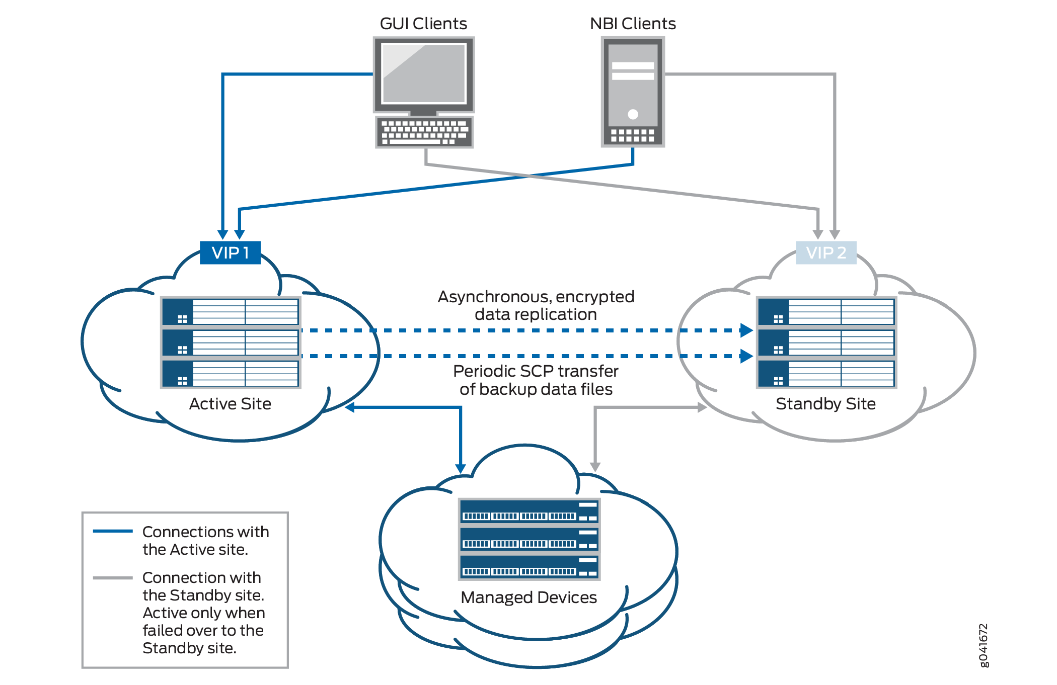
During the normal operation of the disaster recovery solution, the GUI and API users and the managed devices are connected to the active site for all network management services. The connectivity between the standby site and managed devices is disabled as long as the active site is functional. When the active site becomes unavailable due to a disaster, the standby site becomes operational. At this time, all services on the standby site are started and the connectivity between the standby site and managed devices is established.
Figure 1 displays the disaster recovery solution.
The disaster recovery watchdog process is initiated at the VIP node of both the active and standby sites to monitor the health of the replication process and detect when the remote site goes down. The disaster recovery watchdog at the local site checks whether there are connectivity issues between both sites (by pinging the nodes at the remote site) and whether the sites are connected to arbiter devices (if you use the device arbitration algorithm).
The disaster recovery watchdog at a site performs the following tasks to confirm connectivity with the remote site and arbiter devices:
Ping the VIP address of the remote site at a regular configurable interval. The default value for the interval is 30 seconds.
For each ping, expect a reply within a configurable timeout interval. The default value for the timeout interval is 5 seconds.
If the local site fails to receive a reply within the timeout interval, the disaster recovery watchdog retries the ping for a configurable number of times. By default, the number of retries is 4.
If all the retries fail, the disaster recovery watchdog at the local site concludes that the VIP address of the remote site is not reachable.
However, the disaster recovery watchdog does not conclude that the remote site is down because the remote site may be switching over the VIP address to a standby node due to a local switchover.
To consider the possibility of a VIP address switchover, the disaster recovery watchdog pings the IP addresses of the other load-balancer nodes at the remote site. If the ping to any of the nodes receives a reply, the disaster recovery watchdog concludes that the remote site is still up.
If the ping to the nodes fails, the disaster recovery watchdog does not conclude that the remote site is down. Instead, the disaster recovery watchdog considers the possibility of connectivity issues between the sites. Both sites will try to become active.
To prevent both sites from trying to become active, the disaster recovery watchdog initiates the device arbitration algorithm and determines whether a failover is required.
A failover is initiated only if the percentage of arbiter devices managed by the active site falls below the failover threshold. Then the active site becomes the standby site and the standby site becomes the active site.
If the percentage of arbiter devices is above the failover threshold, the standby site remains standby and the active site remains active. The percentage of arbiter devices managed by the active site is configurable and its default value is 50%.
The failover is initiated if the following conditions are met:
The standby site cannot reach the VIP address of the active site or the node IP addresses of other load-balancer nodes at the active site.
The percentage of the arbiter devices managed by the active site is below the failover threshold.
For more information about the device arbitration algorithm, see Failure Detection by Using the Device Arbitration Algorithm.
Prerequisites to Configure Disaster Recovery
You need to ensure that your Junos Space installation meets the following prerequisites before you configure disaster recovery:
The Junos Space cluster at the primary or active site (which can be a single node or multiple nodes) and the cluster at the remote or standby site (which can be a single node or multiple nodes) must be set up in exactly the same way, with all the same applications, device adapters, same IP family configurations, and so on.
Both clusters should be configured with SMTP server information from the Junos Space user interface. For more information, see Managing SMTP Servers. This configuration enables the clusters at both the active site and the standby site to notify the administrator by e-mail if the replications fail.
The number of node(s) in active site and standby site should be the same.
Connectivity Requirements to Configure Disaster Recovery
You need to ensure that the disaster recovery solution meets the following connectivity requirements before you configure disaster recovery:
Layer 3 connectivity between the Junos Space clusters at the active and standby sites. This means:
Every node in a cluster can successfully ping the VIP address of the other cluster
Every node in a cluster can use SCP to transfer files between the active and standby sites
Database replication across the two clusters is possible through TCP ports 3306 (MySQL database replication) and 5432 (PostgreSQL database replication)
The bandwidth and latency of the connection between the two clusters are such that real-time database replication is successful. Although the exact bandwidth required depends on the amount of data transferred, we recommend a minimum of a 100-Mbps bandwidth connection with a latency of fewer than 150 milliseconds.
Independent Layer 3 connectivity between each cluster and managed devices
Independent Layer 3 connectivity between each cluster and GUI or NBI clients
To set up the disaster recovery process, see Configuring the Disaster Recovery Process Between an Active and a Standby Site.
Disaster Recovery Watchdog
The disaster recovery watchdog, also known as a DR watchdog, is an in-built Junos Space mechanism to monitor the integrity of data replication (MySQL database, PgSQL database, configuration files, and RRD files) across sites. The disaster recovery watchdog also monitors the overall health of the disaster recovery setup, initiates a failover from the active to the standby site when the active site fails, and enables the standby site to resume network management services with minimal service disruption. An instance of the disaster recovery watchdog is initiated at the VIP node on both sites when you start the disaster recovery process.
The disaster recovery watchdog provides the following services:
- heartbeat
- mysqlMonitor
- pgsqlMonitor
- fileMonitor
- arbiterMonitor
- configMonitor
- serviceMonitor
- notification
heartbeat
The heartbeat service between the active and standby sites uses ping to check the connectivity between the sites. Both sites send heartbeat messages to each other. The heartbeat service performs the following tasks:
Detect a failure at the remote site by pinging the remote site at regular intervals.
When the remote site fails to reply, rule out the possibility of a temporary issue due to a local failover at the remote site.
Enable or disable automatic failover depending on the disaster recovery configuration settings.
Avoid split-brain scenarios by running the device arbitration algorithm (default) or the logic configured in the custom script.
Verify the disaster recovery configuration after a site is rebooted.
mysqlMonitor
The mysqlMonitor service performs the following tasks:
Monitor the health of MySQL database replication within the site and between the active and standby sites.
Fix MySQL database replication errors.
Notify the administrator through e-mail if any of the MySQL database replication errors cannot be fixed automatically.
pgsqlMonitor
The pgsqlMonitor service performs the following tasks:
Monitor the health of PgSQL database replication within the site and between the active and standby sites.
Fix PgSQL database replication errors.
Notify the administrator through e-mail if any of the PgSQL database replication errors cannot be fixed automatically.
fileMonitor
The fileMonitor service performs the following tasks:
Monitor the health of the configuration files and RRD files replicated within the sites and between the active and standby sites.
Fix errors found during the replication of configuration files and RRD files.
Notify the administrator through e-mail if any of the replication errors cannot be fixed automatically. You can also view the replication errors in the output of the cron job.
arbiterMonitor
The arbiterMonitor service periodically checks whether the local site can ping all the arbiter devices. If the percentage of arbiter devices that are reachable falls below a configured warning threshold (70%, by default), an e-mail notification is sent to the administrator.
configMonitor
The configMonitor service performs the following tasks:
Monitor the disaster recovery configuration files at all nodes at both sites.
Transfer the configuration files across nodes within a site if the files are not in sync.
serviceMonitor
The serviceMonitor service performs the following tasks:
Monitor the status of selected services (such as jboss, jboss-dc, httpd, and dr-watchdog) within a specific site.
Start or stop the selected services if they display an incorrect status.
notification
The notification service notifies the administrator about error conditions, warnings, or disaster recovery state changes detected by the disaster recovery watchdog through e-mail. Notification e-mails are sent if:
Automatic failover is disabled due to connectivity issues between a site and arbiter devices.
The percentage of arbiter devices that are reachable is lower than the warning threshold.
A site becomes standby or active.
The standby site cannot back up files from the active site through SCP.
A site cannot establish an SSH connection to the remote site.
The local site cannot fetch the hostname of the MySQL primary node.
A site cannot fix MySQL and PgSQL database replication errors.
The notification service does not send e-mails to report the same errors within a configurable period of time (by default, 3600 seconds).
Failure Detection by Using the Device Arbitration Algorithm
A device arbitration algorithm is used to detect failure at a site. A list of highly reachable devices running Junos OS and managed by Junos Space Platform are selected as arbiter devices. We recommend that you select arbiter devices based on the following criteria:
You must be able to reach the arbiter devices through Junos Space–initiated SSH connections from both sites. Do not select devices that use device-initiated connections to Junos Space Platform.
You must be able to ping arbiter devices from both disaster recovery sites.
You must choose arbiter devices that stay connected to Junos Space Platform or are less frequently rebooted or shut down because this may impact the device arbitration algorithm results. If you foresee that certain arbiter devices will be offline during some part of their lives, avoid choosing those devices.
You must choose arbiter devices from different geographical locations to ensure that a problem in the management network at a location does not make all arbiter devices unreachable from your sites.
You cannot select NAT and ww Junos OS devices as arbiter devices.
The device arbitration algorithm at the active site uses ping to connect to arbiter devices from the active site. The device arbitration algorithm at the standby site logs in to the arbiter devices through SSH connections by using the login credentials from the Junos Space Platform database. Following are the workflows of the device arbitration algorithm at the active and standby sites.
At the active site:
Ping all selected arbiter devices.
Compute the percentage of arbiter devices that can be pinged.
Check whether the percentage of arbiter devices that can be pinged is above or the same as the configured value of the failover threshold.
If the percentage of arbiter devices connected is above or the same as the configured value of the failover threshold (failureDetection.threshold.failover parameter in the watchdog section of the disaster recovery API), failover is not initiated because the active site is managing a majority of the arbiter devices.
If the percentage of arbiter devices is below the configured value of the failover threshold, failover is initiated (if automatic failover is enabled) and the active site becomes standby. If automatic failover is disabled, the active site remains active.
At the standby site:
Log in to arbiter devices through SSH connections.
Execute a command on each arbiter device to retrieve the list of SSH connections to any node (managed by the node) at the active site.
Calculate the percentage of arbiter devices managed by the active site.
Calculate the percentage of arbiter devices that cannot be reached through SSH connections.
If the percentage of arbiter devices managed by the active site is above or the same as the configured value of the failover threshold, failover is not required because the active site is still managing a majority of the arbiter devices.
If the percentage of arbiter devices managed by the active site is below the configured value of the failover threshold, the disaster recovery watchdog concludes that a failover may be required.
However, because the devices that cannot be reached from the standby site may be connected and managed by the active site, the standby site assumes that all arbiter devices that cannot be reached are being managed by the active site and calculates the new percentage of devices managed by the active site.
If the percentage of devices managed by the active site is below the threshold percentage to adjust managed devices (failureDetection.threshold.adjustManaged parameter in the watchdog section of the disaster recovery API, the default value is 50%), the standby site remains standby. By default, the threshold percentage to adjust managed devices must be below the failover threshold.
If the new percentage calculated by adding the devices managed by the active site and arbiter devices that cannot be reached is below the failover threshold, the disaster recovery watchdog concludes that a failover must be initiated.
If automatic failover is enabled, the standby site initiates the process of becoming active. If automatic failover is disabled, no failover happens.
If you disabled automatic failover or the feature was disabled
due to connectivity issues, you must execute jmp-dr manualFailover at the standby site to resume network management services from the
standby site.
Failure Detection by Using the Custom Failure-Detection Scripts
In addition to using the device arbitration algorithm, you can
create custom failure-detection scripts (sh, bash, Perl, or Python)
to decide when or whether to fail over to the standby site. Custom
failure scripts invoke the jmp-dr api v1 config ––include command and fetch the disaster recovery configuration and the status
of the disaster recovery watchdog services. The disaster recovery
configuration and the status of the disaster recovery watchdog services
at a site are organized as various sections. Table 1 lists these sections.
Use the -- include <section-name> option to view the details of a section or use the details of the section in the custom failure-detection script.
Section |
Description |
Details Included in the Section |
Sample Output |
|---|---|---|---|
role |
Disaster recovery role of the current site |
Roles can be active, standby, or standalone. |
– |
failover |
Type of failover that happened last |
Value can be active_to_standby, standby_to_active, or empty if failover has not happened yet. |
– |
core |
Core disaster recovery configuration that includes the remote site node details |
peerVip–VIP of the load-balancer at the remote site adminPass–Encrypted administrator passwords of the remote site. Multiple entries are separated by commas. scpTimeout–Timeout value used to detect SCP transfer failures between sites peerLoadBalancerNodes–Node IP addresses of the load-balancer nodes at the remote site. Multiple entries are separated by commas. peerBusinessLogicNodes–Node IP addresses of the JBoss nodes at the remote site. Multiple entries are separated by commas. peerDeviceMgtIps–Device management IP addresses of the remote site. Multiple entries are separated by commas. |
{
"core": {
  "peerVip": "10.155.90.210",
  "adminPass": "ABCDE12345",
  "scpTimeout": 120,
  "peerLoadBalancerNodes": "10.155.90.211",
   "peerBusinessLogicNodes": "10.155.90.211",
   "peerDeviceMgtIps": "10.155.90.211"}
}
|
mysql |
Disaster recovery configuration related to the MySQL database at the remote site |
hasDedicatedDb–Whether the remote site includes dedicated database nodes peerVip–VIP of the MySQL nodes at the remote site (either normal node or dedicated database node) peerNodes–Node IP addresses of the MySQL nodes at the remote site (either normal node or dedicated DB node). Multiple entries are separated by commas. |
{ "mysql": {
   "hasDedicatedDb": false,
   "peerVip": "10.155.90.210",
   "peerNodes": "10.155.90.211"
   }
}
|
pgsql |
Disaster recovery configuration related to the PgSQL database at the remote site |
hasFmpm–Whether the remote site includes specialized FMPM nodes peerFmpmVip–VIP of the PostgreSQL nodes at the remote site (either normal node or FM/PM specialized node) peerNodes–Node IP addresses of the PostgreSQL nodes at the remote site (either normal node or FM/PM specialized node). Multiple entries are separated by commas. |
{ "psql": {
  "hasFmpm": false,
  "peerFmpmVip": "10.155.90.210",
  "peerNodes": "10.155.90.211"
  }
}
|
file |
Configuration and RRD files–related disaster recovery configuration at the remote site |
backup.maxCount–Maximum number of backup files to retain backup.hoursOfDay–Times of the day to back up files backup.daysOfWeek–Days of the week to back up files restore.hoursOfDay–Times of the day to poll files from the active site restore.daysOfWeek–Days of the week to poll files from the active site |
{ "file": {
  "backup": {
    "maxCount": 3,
    "hoursOfDay": "*",
    "daysOfWeek": "*" },
  "restore": {
    "hoursOfDay": "*",
"daysOfWeek": "*" }
  }
}
|
watchdog |
Disaster recovery configuration related to the disaster recovery watchdog at the current site |
heartbeat.retries–Number of times to retry the heartbeat message heartbeat.timeout–Timeout of each heartbeat message in seconds heartbeat.interval–Heartbeat message interval between sites in seconds notification.email–Contact e-mail address to report service issues notification.interval–Dampening interval between receiving e-mails about affected services failureDetection.isCustom–Whether the remote site uses custom failure detection failureDetection.script–Path of the failure-detection script failureDetection.threshold.failover–Threshold percentage to trigger a failover failureDetection.threshold.adjustManaged–Threshold percentage to adjust the percentage of managed devices failureDetection.threshold.warning–Threshold percentage to send a warning to ensure that a disaster recovery site can reach more arbiter devices to improve the accuracy of the device arbitration algorithm failureDetection.waitDuration–Grace period to allow the original active site to become active again when both sites become standby failureDetection.arbiters–List of arbiter devices |
{ "watchdog": {
  "heartbeat": {
"retries": 4,
"timeout": 5,
"interval": 30 },
  "notification": {
    "email": "abc@example.com",
    "interval": 3600 },
  "failureDetection": {
"isCustom": false,
"script": "/var/cache/jmp-geo/watchdog/bin/arbitration",
    "threshold": {
      "failover": 0.5,
      "adjustManaged": 0.5,
      "warning": 0.7 },
      "waitDuration": "8h",
      "arbiters": [{
        "username": "user1",
        "password": "xxx",
        "host": "10.155.69.114",
        "port": 22,
        "privateKey": ""
      }]
}
  }
}
|
deviceManagement |
Device management IP addresses at the remote site |
peerNodes–Device management IP addresses of the remote site. Multiple entries are separated by commas. nodes–Device management IP addresses at the current site. Multiple entries are separated by commas. ip–Device management IP address and interface on this
node (node on which the |
{ "deviceManagement": {
   "peerNodes": "10.155.90.211",
   "nodes": "10.155.90.222",
”ip”: “10.155.90.228,eth0”
 }
}
|
states |
Runtime information of the disaster recovery watchdog services at the current site. If the disaster recovery watchdog has never run on this site, this section is not available. If the disaster recovery watchdog has stopped, the information in this section is out-of-date. |
– |
{ "states": {
    "arbiterMonitor": {
      "progress": "idle",
      "msg": {
        "service": "arbiterMonitor",
        "description": "",
        "state": true,
        "force": false,
        "progress": "unknown",
        "payload": {
          "code": 0
        },
        "time": "2015-07-18T22:18:55+00:00"
      },
"service": {}
}, |
    "configMonitor": {
      "progress": "idle",
      "msg": {
        "service": "configMonitor",
        "description": "",
        "state": true,
        "force": false,
        "progress": "unknown",
        "payload": {
          "code": 0
        },
        "time": "2015-07-18T22:19:15+00:00"
      },"service": {}
    },
|
|||
    "fileMonitor": {
      "progress": "idle",
      "msg": {
        "service": "fileMonitor",
        "description": "",
        "state": true,
        "force": false,
        "progress": "unknown",
        "payload": {
          "code": 0
        },
        "time": "2015-07-18T22:18:59+00:00"
      },
"service": {}
    },
|
|||
    "heartbeat": {
      "progress": "unknown",
      "msg": {
        "service": "heartbeat",
        "description": "",
        "state": true,
        "force": false,
        "progress": "unknown",
        "payload": {
          "localFailover": false
        },
        "time": "2015-07-18T22:17:49+00:00"
      },
"service": {
        "booting": false,
        "bootEndTime": null,
        "waitTime": null,
        "automaticFailover": false,
        "automaticFailoverEndTime": "2015-07-18T07:41:41+00:00"
      }
    },
|
|||
"mysqlMonitor": {
      "progress": "idle",
      "msg": {
        "service": "mysqlMonitor",
        "description": "",
        "state": true,
        "force": false,
        "progress": "unknown",
        "payload": {
          "code": 0
        },
        "time": "2015-07-18T22:19:09+00:00"
      },
"service": {}
    },
|
|||
    "pgsqlMonitor": {
      "progress": "unknown",
      "msg": {
        "service": "pgsqlMonitor",
        "description": "Master node pgsql in active or standby site maybe CRASHED. Pgsql replication is in bad status. Please manually check Postgresql-9.4 status.",
        "state": false,
        "force": false,
        "progress": "unknown",
        "payload": {
          "code": 1098
        },
        "time": "2015-07-18T22:18:27+00:00"
      },"service": {}
    },
|
|||
    "serviceMonitor": {
      "progress": "running",
      "msg": {
        "service": "serviceMonitor",
        "description": "",
        "state": true,
        "force": false,
        "progress": "unknown",
        "payload": {
          "code": 0
        },
        "time": "2015-07-18T22:19:30+00:00"
      },
"service": {}
    }
  }
} |
The output from the custom script informs the disaster recovery watchdog whether a failover to the standby site is required. The disaster recovery watchdog interprets the output from the script in the JSON format. The following is an example:
{
  "state": "active",
  "action": "nothing",
  "description": "",
  "payload": {
    "waitTime": "",
    "details": {
      "percentages": {
        "connected": 1,
        "arbiters": {
          "10.155.69.114": "reachable"
        }
      }
    }
  }
}
Table 2 describes the details of the script output.
Property |
Description |
Data Type |
Values or Format |
Other Details |
|---|---|---|---|---|
state |
Current disaster recovery role of this site |
String |
active standby |
Required An empty string is not allowed. |
action |
Action that the disaster recovery watchdog must perform |
String |
beActive–Change role to active. beStandby–Change role to standby. nothing–Do not change role. wait–Wait in the current role for the time specified in the payload.waitTime property. |
Required An empty string is not allowed. |
description |
Description of the action field and the message that is sent in the e-mail notification |
String |
– |
Required An empty string is allowed. |
payload.waitTime |
End time of the grace period when both sites become standby |
String (Date) |
YYYY-MM-DD, UTC time in HH:MM+00:00 format |
Required An empty string is allowed. This property is used when you specify the value of action as wait. |
payload.details |
User- customized information that can be used to debug the script |
– |
JSON object |
Optional An empty string is not allowed. |
Steps to Configure Disaster Recovery
To configure disaster recovery between an active site and a standby site:
Stop the disaster recovery process configured during earlier releases before upgrading to Junos Space Network Management Platform Release 15.2R1. For more information on the upgrade process, see the Upgrade Instructions section in the Junos Space Network Management Platform Release Notes 15.2R1.
For more information about stopping the disaster recovery process configured during earlier releases, see Stopping the Disaster Recovery Process on Junos Space Network Management Platform Release 14.1R3 and Earlier.
You do not require to perform this step for a clean installation of Junos Space Network Management Platform Release 15.2R1.
Set up SMTP servers at both sites from the Junos Space user interface to receive notifications. For more information, see Managing SMTP Servers in the Junos Space Network Management Platform Workspaces User Guide.
Copy the file with the list of arbiter devices (if you are using the device arbitration algorithm) or the custom failure-detection script to the appropriate location at the active site. Ensure that all arbiter devices are discovered at the active site. For more information, see Device Discovery Profiles Overview in the Junos Space Network Management Platform Workspaces User Guide.
Configure the disaster recovery configuration file at the active site. The disaster recovery configuration includes SCP settings to synchronize configuration and RRD files, heartbeat settings, notifications settings, and the failure-detection mechanism.
Configure the disaster recovery configuration file at the standby site. The disaster recovery configuration includes SCP settings to synchronize configuration and RRD files, heartbeat settings, and notification settings.
Start the disaster recovery process from the active site.
For more information, see Configuring the Disaster Recovery Process Between an Active and a Standby Site.
Disaster Recovery Commands
You use the disaster recovery commands listed in Table 3 to configure and manage disaster
recovery sites. You must execute these commands at the VIP node of
the site. You can use the --help option with these commands
to view more information.
Command |
Description |
Options |
|---|---|---|
|
Initialize the disaster recovery configuration files at both sites. You need to enter values for the parameters prompted by the command. Create MySQL and PgSQL users and passwords required to replicate data and monitor the replication across disaster recovery sites. The following users are created:
|
|
|
||
|
Start the disaster recovery process at both sites. You must execute this command at the VIP node of the active
site. The active site establishes an SSH connection to the standby
site and executes the When you execute this command, MySQL database and PgSQL database replication and configuration and RRD files backup to the standby site are initiated. You execute this command:
|
|
|
||
|
When the command is executed without options, the command:
You must execute the command in the following order:
You must execute this command at the VIP node of the local site to modify the configuration and the VIP node of the remote site to accept the modified configuration. |
Use these options to modify the disaster recovery configuration at a site and update the change at the peer site: |
|
||
|
||
|
||
|
||
|
||
|
||
|
Check the status of the disaster recovery process. The command checks whether MySQL and PgSQL databases are replicated and configuration and RRD files are backed up, and verifies the status of the disaster recovery watchdog and reports errors. |
– |
|
Stop the disaster recovery process between sites. When you execute this command, MySQL and PgSQL database replication and configuration and RRD files backup between sites are stopped. The disaster recovery data files are not deleted. The status of services such as JBoss, OpenNMS, Apache remains unchanged. |
– |
|
Stop the disaster recovery process and delete the disaster recovery data files from a site. The site initiates services as a standalone cluster. You must execute this command at the VIP node of both sites to stop the disaster recovery process completely and delete the disaster recovery data files from both sites. |
– |
|
Manually fail over to the standby site. When you execute this command, the standby site becomes the new active site and the active site becomes the new standby site. |
|
|
||
|
Enable automatic failover to the standby site or disable automatic failover to the standby site for a specified duration. Note:
You can execute this command only if the disaster recovery watchdog is active at the site. |
|
|
||
|
View the disaster recovery configuration and runtime information in the JSON format. |
|
When you include this command in a custom failure-detection script, the command fetches the disaster recovery configuration and status of the disaster recovery watchdog services and executes the logic in the script. |