Add EVPN-VPWS Site and Site Network Access Details
An EVPN-VPWS service is provisioned on a point-to-point connection between two sites over an MPLS network. Use the Customer Site Settings page of the Add E-Line EVPN VPWS CSM wizard to enter details of sites that you want to connect to the EVPN-VPWS.
Before adding the EVPN-VPWS service site details, you must create a new EVPN-VPWS service instance and enter general details about the service. Follow steps 1 to 4 of the Add an EVPN-VPWS Service Instance to create a new instance and add general details.
You can configure the following on the Customer Site Settings page:
-
Add site details (site ID, location, and devices parameters). See Add EVPN-VPWS Site.
-
Add parameters for site network access (connection with the service provider network). See Add EVPN or EVPN-VPWS Site Network Access Parameters.
Add EVPN-VPWS Site
A site refers to the geographical area where the VPN service spans.
To add an EVPN-VPWS service site on the Customer Site Settings page:
Click the add (+) icon on the top-right corner of the Customer Sites section.
The Add Site page appears.
Enter site details by referring to the following table:
Table 1: Fields on the Add Site Page (EVPN-VPWS) Field Description Site Id*
Enter a unique site ID to identify the customer site in the network. For example, site1.
The site ID can contain alphanumeric characters and special characters hyphens (-) and underscores (_). The maximum number of characters allowed is 64.
Locations
Location Id*
Enter a unique ID for a location in the site. For example, MAN for Manhattan and BRO for Brooklyn in the New York site.
Address
Enter the address (number and street) of the location in a site. For example, 123, Avenue Street.
City
Enter the city where the site is located. For example, MAN for Manhattan.
Country Code
Enter the ISO alpha-2 code of the country where the site is located, for example, ZA for South Africa and CH for Switzerland.
Postal Code
Enter the postal code of the location in the site. For example, 100XX for New York.
State
Enter the state in which the site is located. If the country doesn't have states, enter the region in which the site is located. For example, NYC for New York City.
Do any of the following:
Click Cancel to exit the Add Site page without saving the changes you made.
Click OK to save the site details you added. The site you added is listed in the Customer Sites table.
You can view the configured properties by expanding Properties.
Add EVPN-VPWS Site Network Access Parameters
After you add a site for the EVPN-VPWS service, you must configure the parameters for site network access (connection) between the site and the service provider network. Site network access refers to a logical Ethernet connection from a site to the L2VPN service in the provider network.
To add site network access parameters:
Select and expand the site-ID in the Customer Sites table.
Expand Site Network Access and click the add (+) icon above the Site Network Access table.
The Add Connection page appears.
Enter the network access ID, device reference values, and access type by referring to the following table:
Table 2: Fields on the Add Connection Page (EVPN-VPWS) Field Description Network Access ID *
Enter a unique ID for the connection between the site and the service provider network. For example, SVL-access-1.
Access Interface (or CE reference)
Enter or select a CE reference device name for the connection.
The name can contain alphanumeric characters (a-z, A-Z, and 0-9) and some special characters [underscore (_), period (.), colon (:), semi-colon (;), hyphen (-), hash (#) , @, $, %, &, *, /, and + only].
To select a CE device for the connection:
Click the search icon (magnifying glass) to the right of the text box.
The Search Access Interface (or CE Interface) page appears.
You can view a list of available interfaces and their details such as PE device, PE interface, VLAN tag types, and the supported VLAN range. You can also view whether the interface is used in the resource pool.
(Optional) Filter the interfaces displayed in the table using the filter criteria.
Click the add icon (+) next to the filter text box. A pop-up window appears with the following fields:
In the Field drop-down list, select a filter criterion from Access Interface, PE, or PE interface.
In the Condition drop-down list, select = (equal to), includes, or in to set the filter condition.
In the Value field, enter the value to filter by.
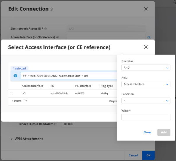
Click Add to add the filter criterion. For example, when you apply PE = epic-7024-28-dc, the table displays all results for PE device, epic-7024-28-dc.
The table automatically refreshes to display only the filtered entries.
(Optional) To add multiple filter criteria, click the Operator drop-down list and select AND or OR.
Repeat step i to add an additional filter criterion.
For example:
When you apply PE = epic-7024-28-dc AND Access Interface = ce5, the table displays all results for PE device, epic-7024-28-dc with ce5 as the access interface.
When you apply PE Interface INCLUDES 0/0/0, the table displays all PE interfaces of type 0/0/0.
When you apply PE = epic-7024-28-dc OR PE = epic-7024-29-dc, the table displays all results from both PEs.
Click Close to exit the filter addition pop-up.
The added filter criterion is displayed and the table automatically displays the filtered entries.
(Optional) You can edit the filter criteria directly from filter text box. Edit the values and click the tick icon to refresh the filtered table entries.
You can also delete the added filter criteria by clicking the X icon.
Note: When you apply filters on multiple fields using AND or OR, the query returns no results. You must use a single-field filter instead.
Select the check box corresponding to the access interface that you want to select as the Access Interface (or CE reference) and click OK.
The selected access interface is displayed in the Access Interface (or CE reference) text box on the Add Connection page.
If you want to change the previously selected CE device, click the search icon (magnifying glass) next to the Access Interface (or CE reference) text box. The Search Access Interface (or CE Interface) page appears. The interfaces displayed in the table is filtered based on the selected CE device.
Click the X icon to clear the search. The table then displays all access interfaces and their details. You can add a new filter from scratch.
Local VPWS ID
Enter a custom VPWS ID for this CE device‑facing site network access.
Enter a value in the range 1 through 16,777,215.
This ID reflects as the remote VPWS ID in the second CE device‑facing device configuration.
If this ID is not entered, the first and second CE device‑facing site network accesses use the default values 1 and 2.
Access Type*
Click the drop-down to select a connection type between the site and service provider network from the following options:
regular—Select regular for standard Layer 2 VPN connection type between the site and service provider network.
By default, the regular connection type is selected.
service—Represents the terminating side of a service stitch (the connector or the right-side of the stitch).
stitching-endpoint—Represents the initiating side of a service stitch (the creator side or the leftside of the stitch).
If you select this access type, a Stitching section is included in the Configure Network Access page. Enter value for the Reference Access Type under Stitching. See Add Stitching Parameters for EVPN-VPWS Site Network Access.
Expand the following sections on the Add Connection page and configure the remaining site network access parameters.
- Add Access Diversity Parameters for EVPN-VPWS Site Network Access
- Add Availability Parameters for EVPN-VPWS Site Network Access
- Add Connection Parameters for EVPN-VPWS Site Network Access
- Add Service Parameters for EVPN-VPWS Site Network Access
- Add Stitching Parameters for EVPN-VPWS Site Network Access
Add Access Diversity Parameters for EVPN-VPWS Site Network Access
Expand Access Diversity and add the access diversity parameters.
A network administrator can group the connections from a site to the service provider network, assign group ID to each connection group, and apply certain constraints to all the connections included in a group. A constraint is expressed in relation to another set of connections (target set). For example, a connection X in a group with group ID G1 must be "PE-diverse" (constraint type) from connections in a target group with group ID G2. The site network access that you are configuring might use the same or different group ID than the target network accesses. You can assign one or more group IDs for a connection, specify constraint types, and select the target group ID that the constraint must be applied to, in the Access Diversity section.
To assign group IDs to a connection and apply constraints to target group IDs:
Expand Access Diversity on the Add Connection page.
Add IDs of groups that the connection is to be a part of:
Expand Groups and click the add (+) icon.
The Group page appears.
Enter one or more IDs of the groups to which the connection must be assigned and click OK.
The group ID entries are listed in the Group ID table.
(Optional) Use the edit or delete options above the Group table to edit or delete the entries.
Expand Constraints and click the add (+) icon above the Constraint table.
The Constraint page appears.
- Add the following parameters on the Constraints page:
Click the Constraint Type drop-down and select constraint type from the following supported options:
Note: Note: To apply the constraint, the connections in a site network access must be in the same group. For example, to ensure that the pop-diverse constraint type is applied on two connections in a site network access, both the connections must be in the same group and target group.pe-diverse—The site network access (connection) must not be connected to the same PE router as the connections in the target group.
pop-diverse—The site network access must not use the same point-of-presence (POP) as the connections in the target group.
Expand Target and click the add (+) icon above the Group ID table.
The Group page appears.
Click the Group ID drop-down to select the group to which you want to apply the constraint and click OK.
The ID you enter is displayed in the Group ID table.
You can add multiple group IDs as target groups to apply the access constraint.
Click OK on the Constraint page.
The constraint types and target group IDs are listed in the Constraint table.
(Optional) Click the edit or delete icons above the Constraint table to edit or delete the entries.
Add Availability Parameters for EVPN-VPWS Site Network Access
Expand Availability and enter the values by referring to the following table:
Table 3: Availability Parameters (EVPN-VPWS) Field Description Access Priority
Enter a value for site network access priority.
Enter a value in the range 0 through 4,294,967,295. The default value is 100.
The access priority parameter defines the preference for the site network access (connection) for load balancing and configuring primary or backup site connections. The higher the access priority value, the higher is the preference for the connection.
Note: If you do not want to configure an access priority, clear the text box to delete the default value.Redundancy Mode
Select the redundancy mode from the following options:
all-active—In this mode, all nodes can forward traffic to and from the Ethernet segment.
single-active—In this mode, only one node forwards traffic to and from the Ethernet segment.
Add Connection Parameters for EVPN-VPWS Site Network Access
Expand connection and add connection parameters:
Click the Ethernet interface type drop-down and select the interface type from the following options:
Tagged—A tagged interface receives and sends Ethernet frames with VLAN tags.
Untagged—An untagged interface receives and sends Ethernet frames without VLAN tags.
Expand Tagged Interface and select dot1q or qinq from the Type drop-down list.
A Dot1q tagged interface transmits and receives Ethernet frames with VLAN tags. VLAN tags are added to the frames based on guidelines defined by the IEEE 802.1Q standard. In the Dot1q method, the service provider tags packets between CE and PE devices with one or more customer VLAN (C-VLAN) IDs.
Select dot1q from the Type drop-down and configure the values by referring to the following table:
Table 4: Dot1q VLAN Tagged Parameters (EVPN-VPWS) Field Description C-VLAN ID*
Enter a unique identifier for the C-VLAN.
Enter a value in the range 1 through 4094.
Tag type
Specify the type of VLAN tag.
Click the Tag type drop-down and select c-vlan. Only the c-vlan tag type is supported this release.
A Q-in-Q tagged interface transmits and receives frames with double VLAN tags—an inner customer VLAN (C-VLAN) and an outer service VLAN (S-VLAN). In the Q-in-Q method, the service provider adds an additional S-VLAN tag outside the C-VLAN tag, creating a double-tagged frame between the CE and PE device.
Table 5: Q-in-Q VLAN Tagged Parameters (EVPN-VPWS) Field Description C-VLAN ID*
Enter a unique identifier for the inner VLAN.
Enter a value in the range 1 through 4094.
S-VLAN ID*
Enter a unique identifier for the outer VLAN.
Enter a value in the range 1 through 4094.
Use S-VLAN ID as Interface Unit
Toggle to True to set the S-VLAN ID as the interface unit value. For example, if the S-VLAN ID is 100, the interface unit value is also set to 100.
Expand Untagged Interface and configure the values by referring to the following table:
Table 6: Untagged Interface Parameters (EVPN-VPWS) Field Description LLDP
Switch the toggle on to set LLDP to True if you want to enable LLDP.
The default setting is False.
Speed
Enter the speed (in Mbps) of the untagged physical interface.
The default value is 10 Mbps.
Expand OAM 802.3ah Link
Enabled
Switch the Enabled toggle on to set it to True, if you want to enable IEEE 802.3ah OAM link. The default setting is False.
Add Service Parameters for EVPN-VPWS Site Network Access
Expand Service > Service Bandwidth and add service parameters.
Click the add (+) icon above the Bandwidth table.
The Bandwidth page appears.
Enter the values by referring to the following table:
Table 7: Service Parameters (EVPN-VPWS) Field Description Direction
Select the direction of service bandwidth:
input-bw—Bandwidth download direction from the service provider network to the site.
output-bw—Bandwidth upload direction from the site to the service provider network.
CBS*
Enter the Committed Burst Size (CBS) in bytes per second.
When network traffic does not utilize the configured Committed Information Rate (CIR), the unused bandwidth is accumulated up to a maximum limit defined by the CBS.
CIR*
Enter the CIR or the maximum number of bits per second (bps) that an interface can send or receive.
The service provider provides the CIR as the guaranteed bandwidth for network traffic that an interface can send or receive in one second, under normal line conditions.
Click OK.
The bandwidth values are listed in the Bandwidth table.
(Optional) Click the edit or delete icons above the Bandwidth table to edit or delete the entries.
Add Stitching Parameters for EVPN-VPWS Site Network Access
Expand Stitching if you select service for Access Type in step 3.
- Select a site network access from the Reference Network
Access drop-down
list.
The Reference Network Access refers to the site network access that is initiating the stitch.
Do any of the following:
Click Cancel to exit the Add Connection page without saving the changes you made.
Click OK to save the connection details you added.
You are returned to the Customer Site Settings page of the Add E-Line EVPN VPWS CSM wizard and the connection you added is listed in the Site Network Access table.
Configure post update placement parameters for the EVPN-VPWS service. See Add EVPN-VPWS Service Post Update Placements Parameters.