Add an L3VPN Service Instance
A superuser or network administrator can use Routing Director to provision an Layer 3 VPN (L3VPN) service in their network.
When you create and save an L3VPN service instance, Routing Director generates a create service order. After you provision the service instance, Routing Director activates the automated workflow for fulfilling the service order and provisions the service in the network.
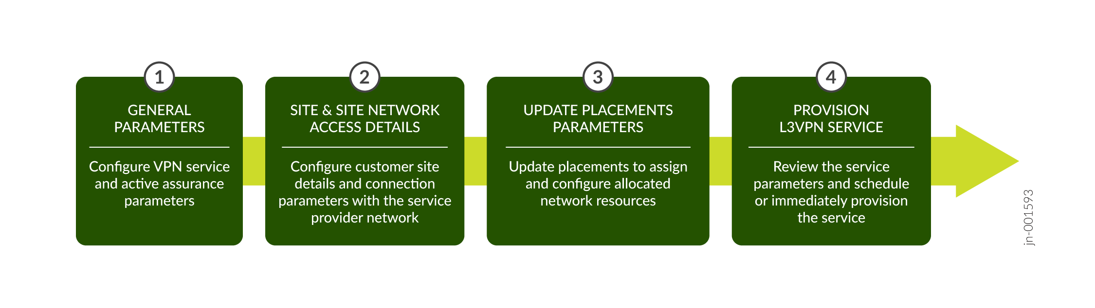
Figure 1 illustrates the high-level workflow for provisioning an L3VPN service.
You can create an L3VPN service instance by uploading a preconfigured JSON file or by entering the details in the GUI fields on the Add L3VPN Service page.
To create an L3VPN service instance:
-
Click Orchestration >
Instances.
The Service Instances page appears.
-
Click Add > L3VPN.
The Add L3VPN wizard appears.
-
On the General page of the Add L3VPN wizard, enter the values by referring to
Table 1.
Note:
Fields marked with an asterisk (*) are mandatory.
Table 1: Fields on the General Page Field
Description
Upload JSON File
Click Browse to upload a preconfigured JSON file.
You see a message that the file is successfully imported. The values specified in the file are automatically populated in the corresponding UI fields.
Customer*
Select the name of the customer for whom you are provisioning the service:
-
If you already added the customer name by using the Customer Inventory page (Orchestration > Service > Customers), select the customer name from the drop-down list.
-
Alternatively, click the Add Customer link to create a new customer. See Add a Customer.
The customer name must be unique within an organization.
Instance name*
Enter a name for the service instance. For example, multihomed-l3vpn.
The instance name can be a set of alphanumeric characters and the special character hyphen (-). The maximum number of characters allowed is 64.
VPN Service VPN Id*
Enter the ID you want to assign to the VPN. For example, vpn10.
The VPN ID must not exceed 64 characters.
VPN Service Topology*
Select a topology for the VPN service:
-
Any-to-any topology—In this service topology, all VPN sites can exchange network traffic with each other without any restrictions.
-
Hub-spoke topology—In this service topology, spoke sites can exchange network traffic with hub sites, but not with other spoke sites. The hub sites can exchange network traffic with other hub sites.
Note: The minimum release required to configure L3VPN hub and spoke topology on ACX Series routers is 24.2R1.
Route Distinguisher Type
Select the route distinguisher (RD) type. The default RD type is Type 0.
If Type 1 is selected, the Type 1 values are populated from the NIP or topo resource pool in the Route Distinguishers table at the bottom of the page when you use the Update Placements button. If Type 0 is selected, the Type 0 values are populated from the VPN resource pool in the Route Distinguishers table at the bottom of the page when you use the Update Placements button.
BGP Color Community
Select the color of the BGP community that you want to assign to the service.
This drop-down list is empty when you provision the service instance for the first time. This list is populated when you use the Update Placements option.
If you want to change a previously assigned color, click the drop-down list and select an alternate color. Or if you do not want to assign any color, click the drop-down list and select the Please select option(s) option to remove the previous selection.
BGP Link Protection
Toggle to True to enable BGP link protection to create protected paths for traffic to restore connectivity quickly in case of a link or node failure. The option is set to False, by default.
Enable BGP PIC Edge
Toggle to True if you want to enable BGP Prefix-Independent Convergence (PIC) Edge. The option is set to False, by default.
When BGP PIC Edge is enabled, the
protect
                                                core
statement is configured under therouting-optionshierarchy in the PE router.BGP PIC Edge allows you to install an L3VPN route, in both IPv4 and IPv6 networks, in the forwarding table as an alternate precomputed path, enabling fast failover when connectivity to a PE router is lost.
Pinned Reservation
Configure the service to use reserved resources (pinned resources).
Brownfield
Enable this flag if this is a brownfield service. When enabled, this service would be provisioned by using resources reserved for migrating brownfield services to Routing Director.
Customer
Enable this flag to allow the service to be provisioned by using resources that are exclusively reserved for the customer associated with this service.
Instance
Enable this flag to allow the service to be provisioned by using resources exclusively reserved for this service.
Service Settings
Enter common settings applicable for the service.
Use instance name instead of UUID in device configuration.
Toggle to True to use the service instance name, instead of UUID, in the device configurations. The specified name is used in configuration such as routing instance name, filter name, policer name, community name, policy statement name, and so on. The instance name must be unique across customers and can be a maximum of 32 characters long.
Disable it to set it to False, so that the service instance name is auto-converted to a UUID and used in the device configuration. The UUID is a system generated alphanumeric value.
This option is disabled, by default.
Active Assurance
Enabled
Toggle to True to enable Active Assurance measurements to monitor the service after it is provisioned.
Active Assurance runs a Test or Monitor to measure the network traffic for the provisioned service. For more information, see Tests and Monitors Overview.
This option is disabled, by default.
Monitors
Toggle to True to enable a Monitor to continously measure the service availability and performance.
Active Assurance runs a Monitor that contains the configurations to monitor the service during the lifetime of the service.
Routing Director enables you to configure plug-ins such as Ping, TWAMP, RPM, and so on to monitor the service.
On Change Tests
Toggle to True to enable a Test to validate a service after it is provisioned.
Active Assurance runs a Test that contains the configurations to validate a provisioned service for a finite amount of time.
-
-
(Optional) Click Update Placements to assign placement
parameters. You can assign placement parameters for route target and route
distinguishers.
View the updated placement parameters and to optionally edit them:
-
Expand Route Target and configure the placement parameters by referring to the following table:
Table 2: Route Target Field Description Number
Enter the number of route targets.
The block size entered when configuring a VPN resource pool is the upper limit for the route target number. The entered block size is displayed to the right of the text box.
Pool
Select a pool value.
The ASN values specified when configuring a VPN resource pool are available as options in the drop-down list.
-
Expand Route Distinguisher and configure the service instance to see the assigned RDs.
Select the PE node and click the edit icon. The Route Distinguisher Type selected-type page appears.
Configure the parameters by referring to the following table:
Table 3: Route Distinguisher Field Description If you selected type0 as the Route Distinguisher Type on the General page:
PE Node
The name of the PE node device.
Pool
The unique RD identifier configured as the ASN in the VPN resource pool.
When the service is configured, the combination of the pool ID and a Routing Director assigned number is visible in the device CLI in the format
pool:number. For example, 60000:9.Number
A unique number assigned to the RD by Routing Director.
If you selected type1 as the Route Distinguisher Type on the General page:
PE Node
Name of the PE node device.
IP Address
Loopback address of the device.
If you want to change the loopback address for the device, you can edit the entry from the available preconfigured loopback addresses. To edit, select the RD, click the pencil icon, and select another loopback address from the drop-down list.
Name
Unique RD identifier populated from the configured names in the topo resource instance.
Assigned Number
A unique number assigned to the RD by Routing Director from the block size configured in the topo resource instance.
To change the assigned number, select the RD, click the pencil icon, and edit the number from the preconfigured range visible next to the textbox.
When the service is configured, the combination of the loopback address and the assigned number is visible in the device CLI in the format
loopback_IP:number. For example, 192.168.1.1:30.
-
-
Do any of
the following:
- Click Next to proceed to the Customer Site Settings page of the Add L3VPN wizard. See Add L3VPN Site and Site Network Access Details.
Click Cancel to discard your changes.
- Configure post update placement parameters for the L3VPN service. See Add L3VPN Service Post Update Placements Site Network Access Parameters.
- View summary of the L3VPN service and then save and provision the service. See View Summary and Provision an L3VPN Service.