ON THIS PAGE
Prepare the Cluster Nodes
This topic describes the steps you must perform to prepare the Paragon Automation cluster nodes for deployment.
To prepare your cluster nodes for deployment on ESXi 8.0, KVM, and Proxmox VE hypervisors, perform the following steps:
-
The creation method differs based on the bare-metal hypervisor on which you want to deploy the cluster.
Download the OVA File
Download and verify the integrity of the OVA file.
-
Download the Paragon Automation Installation OVA file from the Juniper Paragon Automation software download site. The OVA is used to create the node VMs and deploy your cluster.
Note that the actual filename will include the release date in it, such as paragon-2.4. X-builddate.ova.
The file is large in size, and it might take considerable time to download it and then create the VMs from your computer. So, we recommend that you create a local installer VM, which can be a basic Ubuntu desktop VM, either on the same server where you want to install Paragon Automation or on a different server. You must be able to download the OVA file to this local installer VM and you must have enough space on the VM to store the file. Configure connectivity to the management IP addresses of the servers as show in Figure 1.
Figure 1: Local Installer VM to download the OVA/OVF files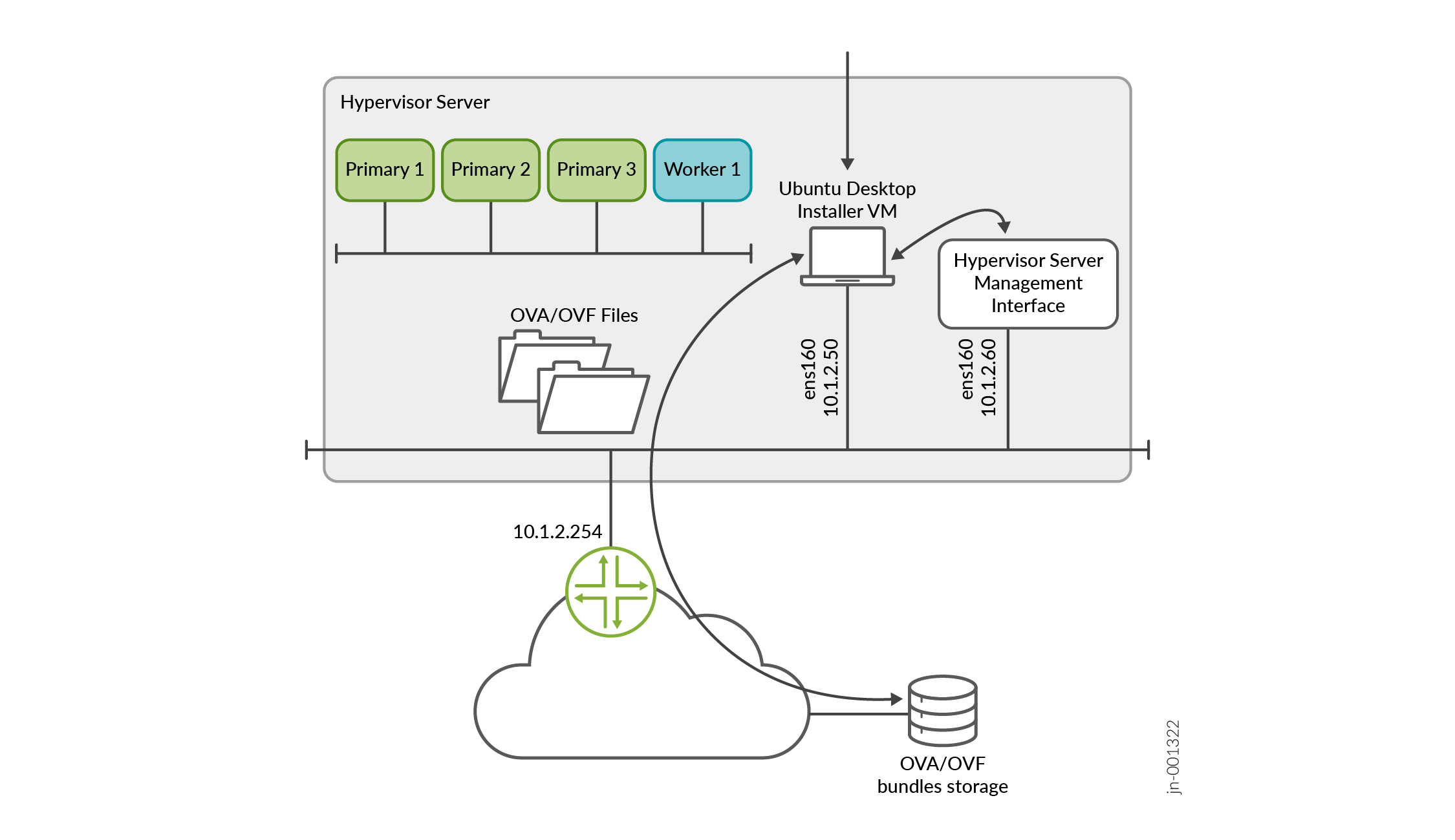
Alternatively, you can use the
wget
                  "http://cdn.juniper.net/software/file-download-url/paragon-2.4.X-builddate.ova"
command to download the OVA directly on to your hypervisor. -
(Optional) Validate the integrity of the OVA file. If you are using an Ubuntu desktop, use the following command:
root@ubuntu:~$ sha512sum paragon-2.4.
                     X-builddate.ova
7deda68aae8ba6399aa95d5365a659a8d579c5562811ebe588972cf0c5107337628370d78dcbdb56ab8ea97e73b7597f3a5ff06e9f501706bd8954b7454b86d2 paragon-2.4.
                     X-builddate.ova
Verify that the number displayed onscreen is the same as the SHA512 checksum number available on the Juniper Paragon Automation software download site. Click Checksums to view the valid SHA512 checksum.
-
On ESXi 8.0
If you are using ESXi 8.0, you can use the OVA directly to create the VMs.
You can also extract and use the OVF and .vmdk files from the OVA to create your VMs. To extract the files, use the following command:
root@ubuntu:# tar -xvf paragon-2.4.
                     X-builddate.ova
paragon-2.4.
                     X-builddate-disk1.vmdk
paragon.-2.4.
                     X-builddate-disk2.vmdk
paragon-2.4.
                     X-builddate-file1.nvram
paragon-2.4.
                     X-builddate.mf
paragon-2.4.
                     X-builddate.ovf
If your installation desktop is running Windows, you can download and use the tar utility from https://gnuwin32.sourceforge.net/packages/gtar.htm to extract the files.
Note:If you are using a stand-alone ESXi 8.0 server without vCenter, due to a limitation of the VMware host client, you cannot upload large OVA files to the client. In such cases, you must extract and use the OVF, .vmdk, and .nvram files to create your VMs.
On KVM and Proxmox VE
If you are using KVM, you must extract the .vmdk files from the OVA using the
tar -xvf paragon-2.4.X-builddate.ovacommand.The rest of this document assumes that the OVA is downloaded to a single KVM server. If you have multiple servers, then download the files onto all the servers. The steps described in this document are general guidelines to create the VMs using the CLI method of deployment. You can also use GUI-based deployment and alter the steps to match your hypervisor requirements. Network configuration of the hypervisor is out of scope of this document.
Now you can create the node VMs.
Create the Node VMs
After verifying the integrity of the OVA file, create the node VMs. Use one of the following methods to create the node VMs based on the hypervisor on which you are deploying the cluster.
On ESXi 8.0
Perform the following steps on ESXi 8.0 hypervisors.
-
From your Web browser, connect and log in to the VMware ESXi 8.0 server where you will install Paragon Automation.
If you are using a local installer VM, use the browser in the VM to connect to the VMware ESXi server.
-
Create the node VMs.
Perform the following steps to create the VMs.
-
Right-click the Host icon and select Create/Register VM.
The New virtual machine wizard appears.
-
On the Select creation type page, select Deploy a virtual machine from an OVF or OVA file.
Click Next.
-
On the Select OVF and VMDK files page, enter a name for the node VM.
Click to upload or drag and drop the OVA file (or the OVF and .vmdk files).
Review the list of files to be uploaded and click Next.
-
On the Select storage page, select the appropriate datastore that can accommodate 300-GB SSD for the node VM. Note that SSD is mandatory.
Click Next. The extraction of files takes a few minutes.
-
On the Deployment options page:
-
Select the virtual network to which the node VM will be connected.
-
Select the Thick disk provisioning option.
-
Enable the VM to power on automatically.
Click Next.
-
-
On the Ready to complete page, review the VM settings.
Click Finish to create the node VM.
Note:If you used the OVF and .vmdk files to create your VMs and the VM creation failed, retry creating the VMs with the .nvram file. On step 2.c, upload the .nvram file along with the OVF and .vmdk files. For standalone ESXi 8.0 servers without vCenter, you must upload the .nvram file as well.
-
To power on the VM, right-click the newly created VM on the Inventory page, and click Power > Power on.
-
Repeat steps 2.a through 2.g for the other three node VMs.
Alternatively, if you are using VMware vCenter, you can right-click the VM, and click the Clone > Clone to Virtual Machine option to clone the newly created VM. Clone the VM three times to create the remaining node VMs.
Enter appropriate VM names when prompted.
-
(Optional) Verify the progress of the VM creation in the Recent tasks section at the bottom of the page. When a VM is created, it appears in the VMware Host Client inventory under Virtual Machines.
-
When all the VMs have been created, verify that the VMs have the correct specifications and are powered on.
-
You have completed the node preparation steps and created all the VMs. You are ready to configure and deploy the cluster. Go to Deploy the Cluster.
On KVM
Perform the following steps on KVM hypervisors with RHEL 8.10 host OS.
In this example, we are deploying the cluster on a single hypervisor server with the following location and naming parameters:
-
Create two VMs each in two data locations (SSDs) on the same hypervisor.
-
/data1/paragon1/for VM1 and /data1/paragon2/ for VM2
-
/data2/paragon3/ for VM3 and /data2/paragon4/ for VM4
Where VM1, VM2, VM3, and VM4 are the four cluster node VMs. We recommend using two SSDs for the node VMs to optimize IOPS rate.
Note: While this example showcases VMs on a single hypervisor server, for server and node high availability, you must create one VM per hypervisor server. -
-
VM1 is named as paragon1, VM2 is named as paragon2, VM3 is named as paragon3, and VM4 is named as paragon4.
-
The two disk images for each VM are named paragon-disk1.img and paragon-disk2.img. Both the disk images for each VM are located in the corresponding paragonx directory. Where x is the VM number (1 through 4).
-
For all VMs, the CPU = 16, RAM = 32-GB, and Mode = host cpu. These are the bare minimum hardware resources that are required on each node VM.
-
VMs are attached to the
br-exbridged network.
Perform the following steps to create the node VMs.
-
Log in to the KVM hypervisor CLI.
-
Ensure that you have the required libvirt, libvirt-daemon-kvm, qemu-kvm, bridge-utils, and qemu-kvm packages installed.
Use the
dnf updateanddnf install libvirt libvirt-daemon-kvm qemu-kvm bridge-utilscommands to install the packages. -
Convert the
.vmdkfiles to the raw format.root@kvm:~/paragon# qemu-img convert -O raw paragon-2.4.X-builddate-disk1.vmdk paragon-disk1.img root@kvm:~/paragon# qemu-img convert -O raw paragon-2.4.X-builddate-disk2.vmdk paragon-disk2.img root@kvm:~/paragon# ls -l total 111327724 -rw-r--r-- 1 root root 268435456000 Feb 13 16:23 paragon-disk1.img -rw-r--r-- 1 root root 53687091200 Feb 13 16:23 paragon-disk2.img -rw-r--r-- 1 64 64 34630534656 Feb 5 10:08 paragon-2.4.X-builddate-disk1.vmdk -rw-r--r-- 1 64 64 74240 Feb 5 10:08 paragon-2.4.X-builddate-disk2.vmdk -rw-r--r-- 1 64 64 8684 Feb 5 10:08 paragon-2.4.X-builddate-file1.nvram -rw-r--r-- 1 64 64 394 Feb 5 09:26 paragon-2.4.X-builddate.mf -rw-r--r-- 1 root root 34679057408 Feb 5 10:08 paragon-2.4.X-builddate.ova -rw-r--r-- 1 64 64 10866 Feb 5 09:26 paragon-2.4.X-builddate.ovf
-
Adjust and expand the disk size. In this example, we have used the bare minimum hardware resources that are required on each node VM.
root@kvm:~/paragon# qemu-img resize -f raw  paragon-disk1.img 300G
Image resized.
root@kvm:~/paragon# qemu-img resize -f raw  paragon-disk2.img 75G
Image resized.
root@kvm:~/paragon# ls -l
total 111327724
-rw-r--r-- 1 root root 322122547200 Feb 13 16:23 paragon-disk1.img
-rw-r--r-- 1 root root  80530636800 Feb 13 16:23 paragon-disk2.img
-rw-r--r-- 1   64   64  34630534656 Feb  5 10:08 paragon-2.4.X-builddate-disk1.vmdk
-rw-r--r-- 1   64   64        74240 Feb  5 10:08 paragon-2.4.X-builddate-disk2.vmdk
-rw-r--r-- 1   64   64         8684 Feb  5 10:08 paragon-2.4.X-builddate-file1.nvram
-rw-r--r-- 1   64   64          394 Feb  5 09:26 paragon-2.4.X-builddate.mf
-rw-r--r-- 1 root root  34679057408 Feb  5 10:08 paragon-2.4.X-builddate.ova
-rw-r--r-- 1   64   64        10866 Feb  5 09:26 paragon-2.4.X-builddate.ovf
-
Create the folders where you want the VMs to be located.
-
/data1/paragon1/ for VM1
-
/data1/paragon2/ for VM2
-
/data2/paragon3/ for VM3
-
/data2/paragon4/ for VM4
-
-
Copy both the
paragon-disk1.imgandparagon-disk2.imgraw disk images to the location of each VM using thecpcopy command. For example,root@kvm:~/paragon# cp paragon-disk1.img /data1/paragon1/.Once copied, the folder and file structure will be similar to:
root@kvm:~/paragon# ls -l /data1/paragon1
total 39852200
-rw-r--r-- 1 root root 322122547200 Feb 28 05:45 paragon-disk1.img
-rw-r--r-- 1 root root  80530636800 Feb 13 16:30 paragon-disk2.img
root@kvm:~/paragon# ls -l /data1/paragon2
total 39792188
-rw-r--r-- 1 root root 322122547200 Feb 28 05:50 paragon-disk1.img
-rw-r--r-- 1 root root  80530636800 Feb 13 16:32 paragon-disk2.img
root@kvm:~/paragon# ls -l /data2/paragon3
total 39789780
-rw-r--r-- 1 root root 322122547200 Feb 28 05:51 paragon-disk1.img
-rw-r--r-- 1 root root  80530636800 Feb 13 16:30 paragon-disk2.img
root@kvm:~/paragon# ls -l /data2/paragon4
total 39796652
-rw-r--r-- 1 root root 322122547200 Feb 28 05:51 paragon-disk1.img
-rw-r--r-- 1 root root  80530636800 Feb 13 16:29 paragon-disk2.img
-
Generate and customize an XML file for configuring each VM.
Configure the machine type as
q35and emulator binary as/usr/libexec/qemu-kvm.A sample XML file for RHEL 8.10 is described here:
<domain type='kvm'>

  <!-- Specify VM name here -->
  <name>paragon1</name>

  <!-- Specify VM RAM size here -->
  <memory unit='KiB'>33554432</memory>
  <currentMemory unit='KiB'>33554432</currentMemory>

  <!-- Specify number of vcpu for the VM here -->
  <vcpu placement='static'>16</vcpu>

  <!--
  For Ubuntu 22.04 KVM use pc-q35-jammy as machine type
  For RHEL 8.10 KVM use q53 as machine type
  -->
  <os>
    <type arch='x86_64' machine='q35'>hvm</type>
  </os>

  <features>
    <acpi/>
    <apic/>
    <vmport state='off'/>
  </features>
  <cpu mode='host-passthrough' check='none' migratable='on'/>
  <clock offset='utc'>
    <timer name='rtc' tickpolicy='catchup'/>
    <timer name='pit' tickpolicy='delay'/>
    <timer name='hpet' present='no'/>
  </clock>
  <on_poweroff>destroy</on_poweroff>
  <on_reboot>restart</on_reboot>
  <on_crash>destroy</on_crash>
  <pm>
    <suspend-to-mem enabled='no'/>
    <suspend-to-disk enabled='no'/>
  </pm>
  <devices>

    <!--
    For Ubuntu 22.04 KVM use /usr/bin/qemu-system-x86_64 as emulator
    For RHEL 8.10 KVM use /usr/libexec/qemu-kvm as emulator
    -->
    <emulator>/usr/libexec/qemu-kvm</emulator>

    <disk type='file' device='disk'>
      <driver name='qemu' type='raw' cache='none' discard='ignore'/>
      <!-- Specify the path to the 1st virtual disk for the main disk -->
      <source file='/data1/paragon1/paragon-disk1.img'/>
      <target dev='vda' bus='virtio'/>
      <boot order='1'/>
      <address type='pci' domain='0x0000' bus='0x05' slot='0x00' function='0x0'/>
    </disk>
    <disk type='file' device='disk'>
      <driver name='qemu' type='raw' cache='none' discard='ignore'/>
      <!-- Specify the path to the 2nd virtual disk for the CEPH OSD disk -->
      <source file='/data1/paragon1/paragon-disk2.img'/>
      <target dev='vdb' bus='virtio'/>
      <address type='pci' domain='0x0000' bus='0x06' slot='0x00' function='0x0'/>
    </disk>
    <controller type='usb' index='0' model='qemu-xhci' ports='15'>
      <address type='pci' domain='0x0000' bus='0x02' slot='0x00' function='0x0'/>
    </controller>
    <controller type='scsi' index='0' model='virtio-scsi'>
      <address type='pci' domain='0x0000' bus='0x03' slot='0x00' function='0x0'/>
    </controller>
    <controller type='sata' index='0'>
      <address type='pci' domain='0x0000' bus='0x00' slot='0x1f' function='0x2'/>
    </controller>
    <controller type='virtio-serial' index='0'>
      <address type='pci' domain='0x0000' bus='0x04' slot='0x00' function='0x0'/>
    </controller>
    <interface type='bridge'>
      <!-- Specify the linux bridge name for the VM to attach to -->
      <source bridge='br-ex'/>
      <model type='virtio'/>
      <address type='pci' domain='0x0000' bus='0x01' slot='0x00' function='0x0'/>
    </interface>
    <serial type='pty'>
      <target type='isa-serial' port='0'>
        <model name='isa-serial'/>
      </target>
    </serial>
    <console type='pty'>
      <target type='serial' port='0'/>
    </console>
    <channel type='unix'>
      <target type='virtio' name='org.qemu.guest_agent.0'/>
      <address type='virtio-serial' controller='0' bus='0' port='1'/>
    </channel>
    <input type='keyboard' bus='ps2'/>

    <!--
    Specify the TCP port for VNC access for GUI console access
    The port number should be uniq and unused TCP port.
    KVM can also allocate dynamic port by setting port='' and autoport='yes'
    -->
    <graphics type='vnc' port='5911' autoport='no' listen='0.0.0.0'>
      <listen type='address' address='0.0.0.0'/>
    </graphics>

    <video>
      <model type='qxl' ram='65536' vram='65536' vgamem='16384' heads='1' primary='yes'/>
      <address type='pci' domain='0x0000' bus='0x00' slot='0x01' function='0x0'/>
    </video>
    <memballoon model='virtio'>
      <address type='pci' domain='0x0000' bus='0x07' slot='0x00' function='0x0'/>
    </memballoon>
    <rng model='virtio'>
      <backend model='random'>/dev/urandom</backend>
      <address type='pci' domain='0x0000' bus='0x08' slot='0x00' function='0x0'/>
    </rng>
  </devices>
</domain>
Save this file as /root/paragon/paragon1.xml. In this example:
-
VM1 is named as paragon1.
-
VM1 CPU = 16, VM1 RAM = 32-GB, VM1 Mode = host cpu
-
VM1 has two image disk images at /data1/paragon1/paragon-disk1.img and /data1/paragon1/paragon-disk2.img
-
The VM is attached to bridged network with name
br-ex -
The VNC port for graphical console is listening on port 5911. If you want to dynamically assign ports, then set
autoport='yes'.
-
-
Define the VM using the XML file.
root@kvm:~/paragon# virsh define paragon1.xml
Domain 'paragon1' defined from paragon1.xml
-
Verify that the VM is registered.
root@kvm:~/paragon# virsh list --all
 Id   Name       State
---------------------------
 -    paragon1   shut off
-
Set the VM to
autostartif the KVM is rebooted.root@kvm:~/paragon# virsh autostart paragon1 Domain 'paragon1' marked as autostarted
-
Power on the VM.
root@kvm:~/paragon# virsh start paragon1
Domain 'paragon1' started
-
Connect to the VM console in one of the following ways:
-
Using the serial console.
Connect to the VM using the serial console.
root@kvm:~/paragon# virsh console paragon1 Connected to domain 'paragon1' Escape character is ^] (Ctrl + ]) OK ] Listening on Journal Socket. [ 6.635248] systemd[1]: Listening on Network Service Netlink Socket. [ OK ] Listening on Network Service Netlink Socket. [ 6.640195] systemd[1]: Listening on udev Control Socket. [ OK ] Listening on udev Control Socket. [ 6.646190] systemd[1]: Listening on udev Kernel Socket. [ OK ] Listening on udev Kernel Socket. [ 6.651480] systemd[1]: Mounting Huge Pages File System... ... ... [ OK ] Reached target Login Prompts. [ OK ] Reached target Multi-User System. [ OK ] Reached target Graphical Interface. Starting Record Runlevel Change in UTMP... [ OK ] Finished Record Runlevel Change in UTMP. epic login: -
Using a VNC client.
Use any VNC compatible client and connect to
kvm-ip::5911.Ensure that the firewall allows port 5911 for communication between your computer and the VM.
-
-
Repeat steps 7 through 12 for the remaining three VMs.
When you create XML files for the remaining three VMs, change the VM name and disk locations as appropriate. Also, change the graphical console port numbers for each VM.
You have completed the node preparation steps and created all the VMs. You are ready to configure and deploy the cluster. Go to Deploy the Cluster.
On Proxmox VE
Perform the following steps on Proxmox VE hypervisors.
In this example, we are installing Paragon Automation on a single server with three provisioned datastores, data0, data1, and data2. data0 is used to save the OVA file, data1 to save the first disk image, and data2 to save the second disk image. The VMs are named, VM1, VM2, VM3, and VM4. We are also configuring the bare minimum hardware resources required to deploy a cluster.
Perform the following steps to create the node VMs.
-
Log in to the Proxmox VE server CLI.
-
Create the data0, data1, and data2 datastores.
-
Copy the OVA to the data0 datastore and extract the .vmdk files.
In this example, we have created a folder called ova in data0, copied the paragon-2.4. X-builddate.ova file to the ova folder, and used the
tar -xvf
                    paragon-2.4.
                           X-builddate.ova
command to extract the files. -
Create the first VM with a VirtIO network interface (net0), and configure the VM name, ID, and memory.
root@proxmox:# qm create 100 --memory 32768 --name VM1 --net0 virtio,bridge=vmbr0Here, the VM ID is 100, VM name is
VM1, and VM memory is 32-GB.Ensure that the VM ID is a unique identifier and is not shared by any other VM on the same server or in the same Proxmox cluster.
-
Configure the total number of vCPUs as 16.
root@proxmox# qm set 100 --sockets 2
update VM 100: -sockets 2
root@proxmox# qm set 100 --cores 8
update VM 100: -cores 8
-
Configure storage for the VM.
root@proxmox# qm set 100 -scsihw virtio-scsi-single
update VM 100: -scsihw virtio-scsi-single
-
Configure the CPU type as host.
root@proxmox# qm set 100 --cpu cputype=host
update VM 100: -cpu cputype=host
-
Navigate to the data0/ova folder.
-
Import disk 1 to the VM as a raw image. Here, import the paragon-2.4.X-builddate-disk1.vmdk file to the data1 datastore.
root@proxmox:/mnt/pve/data0/ova# qm importdisk 100 paragon-2.4.X-builddate-disk1.vmdk data1
importing disk 'paragon-2.4.X-builddate-disk1.vmdk' to VM 100 ...
Formatting '/mnt/pve/data1/images/100/vm-100-disk-0.raw', fmt=raw size=268435456000 preallocation=off
transferred 0.0 B of 250.0 GiB (0.00%)
transferred 2.5 GiB of 250.0 GiB (1.00%)
transferred 5.0 GiB of 250.0 GiB (2.00%)
transferred 7.5 GiB of 250.0 GiB (3.00%)

...
<output snipped>
...

transferred 250.0 GiB of 250.0 GiB (100.00%)
unused0: successfully imported disk 'data1:100/vm-100-disk-0.raw'
-
Import disk 2 to the VM as a raw image. Here, import the paragon-2.4.X-builddate-disk2.vmdk file to the data2 datastore.
root@proxmox:/mnt/pve/data0/ova# qm importdisk 100 paragon-2.4.X-builddate-disk2.vmdk data2
importing disk 'paragon-2.4.X-builddate-disk2.vmdk' to VM 100 ...
Formatting '/mnt/pve/data2/images/100/vm-100-disk-0.raw', fmt=raw size=53687091200 preallocation=off
transferred 0.0 B of 50.0 GiB (0.00%)
transferred 50.0 GiB of 50.0 GiB (100.00%)
unused1: successfully imported disk 'data2:100/vm-100-disk-0.raw'
-
Assign the raw disks to virtio0 and virtio1 and configure the IO thread, backup, discard, and replication options and as shown.
root@proxmox:/mnt/pve/data0/ova# qm set 100 -virtio0 data1:100/vm-100-disk-0.raw,backup=0,replicate=no,discard=on,iothread=on
update VM 100: -virtio0 data1:100/vm-100-disk-0.raw,backup=0,replicate=no,discard=on,iothread=on
root@proxmox:/mnt/pve/data0/ova# qm set 100 -virtio1 data2:100/vm-100-disk-1.raw,backup=0,replicate=no,discard=on,iothread=on
update VM 100: -virtio1 data2:100/vm-100-disk-1.raw,backup=0,replicate=no,discard=on,iothread=on
-
Assign a boot device for the VMs.
root@proxmox:/mnt/pve/data0/ova# qm set 100 --boot c --bootdisk virtio0
update VM 100: -boot c -bootdisk virtio0
Disk 1 is the boot device and Disk 2 is used for Ceph storage.
-
(Optional) Configure the VM to be a non-ballooning device.
root@proxmox:/mnt/pve/data0/ova# qm set 100 --balloon 0
update VM 100: -balloon 0
-
(Optional) If you are not using a GUI for the OS, set tablet as 0 to save on CPU and memory.
root@proxmox:/mnt/pve/data0/ova# qm set 100 --tablet 0
update VM 100: -tablet 0
-
(Optional) Set the display option to Standard VGA to save on CPU and memory.
root@proxmox:/mnt/pve/data0/ova# qm set 100 --vga std
update VM 100: -vga std
-
(Optional) If you want to connect to the VM console using the CLI, configure a serial terminal using a socket.
root@proxmox:/mnt/pve/data0/ova# qm set 100 --serial0 socket
update vm 100: -serial0 socket
-
Power on the VM.
root@proxmox:/mnt/pve/data0/ova# qm start 100 -
Launch the VM console.
-
Using CLI—If you have configured a serial terminal, you can access the VM console through the CLI using the following command.
root@proxmox:/mnt/pve/data0/ova# qm terminal 100The VM console appears.
-
Using the GUI—Log in to the Proxmox VE GUI. Select the powered-on VM1, and click >_ Console. The VM console appears.
-
-
Repeat steps 4 through 18 for the other three VMs. Enter appropriate unique VM IDs and names.
You have completed the node preparation steps and created all the VMs. You are ready to configure and deploy the cluster. Go to Deploy the Cluster.