
Marvis Minis Overview
This page describes how Marvis Minis validates connectivity across the data center network.
Marvis Minis Overview
In a data center network, the devices and services are spread across potentially complex topologies involving overlay virtual networks and multiple VRFs. The paths connecting the devices and services across the network might involve the overlay fabric, VRF leaking, gateway routing, and so on. Data center networks can experience operational issues due to hardware failures, link issues, or infrastructure malfunctions, leading to network breakages and latencies. When such issues arise, a major concern is whether critical services in the data center remain reachable. Furthermore, network engineers frequently deploy new services or upgrade existing ones. These deployments require connectivity to be intact across the potentially complex networks. Network reachability is verified by repeatedly checking connectivity across multiple leaf devices. However, manually verifying each network path is impractical at scale. Marvis Minis helps by periodically checking connectivity and reachability of the devices in the network infrastructure.
Marvis Minis in Data Center Assurance are probes that contain test configurations and run at defined intervals to assess the connectivity and reachability of your network. By proactively simulating network connections, Marvis Minis helps detect and resolve issues before they affect users.
The Marvis Minis feature helps validate network connectivity between devices, services, and clients across the fabric in the following ways:
-
Assessing the connectivity between clients within the data center fabric and the services hosted in the data center.
-
Performing periodic validations to assess connectivity across the underlay and overlay networks and monitoring the overall health of the paths between network components.
-
Helping engineers identify problem areas in the network.
Marvis Minis currently performs the following validations:
-
Service Connectivity—checks the end-to-end connectivity from any client to any service destination.
-
Fabric Connectivity—checks the connectivity from each leaf to every other leaf within the network.
The Marvis Minis feature requires your Data Center Director instance to be running version 6.1 or higher.
You can create test configurations and schedule them to run periodically on the specified devices and services to check connectivity in the network.
The Marvis Minis dashboard displays a graph with the pass and fail counts of the test configs run during the selected time period. It also displays the total number of test configs run for service and fabric connectivity along with the number of failed test configs. The results of each test configuration are also displayed in a list with details such as test configuration type, site, duration, and progress.
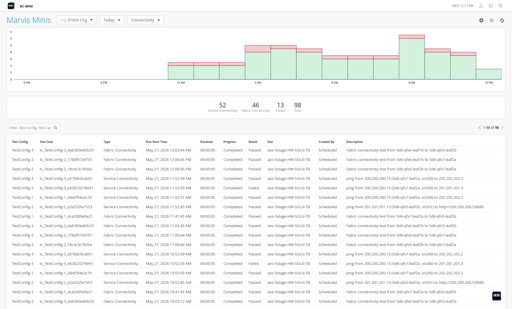
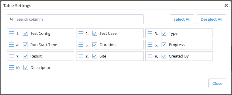
You can modify the page to display information for the entire org for a specific time period. Use the filter icon on the top right of the page to select columns for table display. You can also use the filter to view specific test configs in the table.
To create test configurations, click the gear icon on the top right of the Marvis Minis dashboard.
Benefits of Marvis Minis
Marvis Minis provides the following benefits:
-
Proactively monitors network reachability and reliability.
-
Enables network administrators to detect performance degradation early, before it impacts applications.
-
Checks whether key service endpoints remain reachable from critical client segments.
Service Connectivity Validation
Marvis Minis runs the service connectivity checks to verify that overlay clients can reach internal or external services by using the Real‑time Performance Monitoring (RPM) probes on the corresponding Junos leaf devices. For more information about RPM, see Understanding Using Probes for Real-Time Performance Monitoring on ACX, MX, and PTX Series Routers and EX and QFX Switches.
Each probe uses a source IP from the client’s overlay segment to simulate client traffic to the target destination and runs every hour, providing continuous visibility into path health.
- Create a Service Connectivity Test Config
- Deploy and Schedule Service Connectivity Test Configs
- Trigger an On-Demand Run for a Service Connectivity Test Config
Create a Service Connectivity Test Config
To create a service connectivity test config:
On the Network Connectivity – Test Configuration page, select the Service Connectivity tab.
Figure 3: Test Configurations for Service Connectivity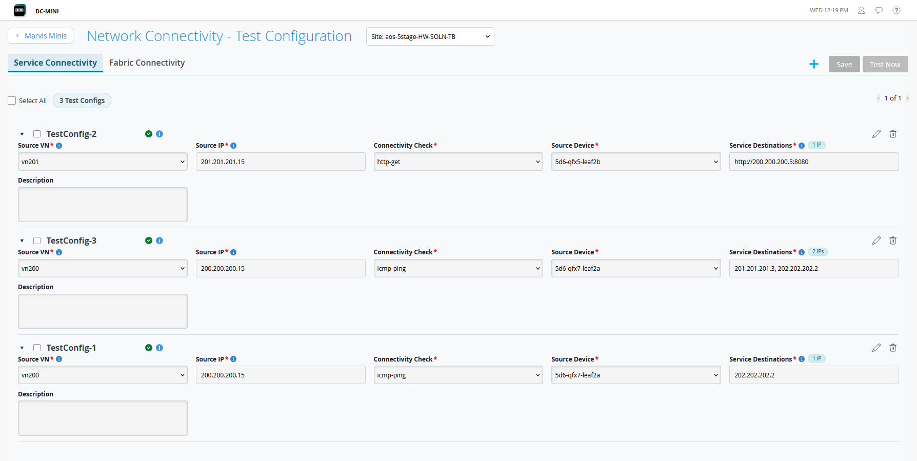
Click the "+" icon. The Create Test Configuration dialog box opens.
Figure 4: Create Test Configuration for Service Connectivity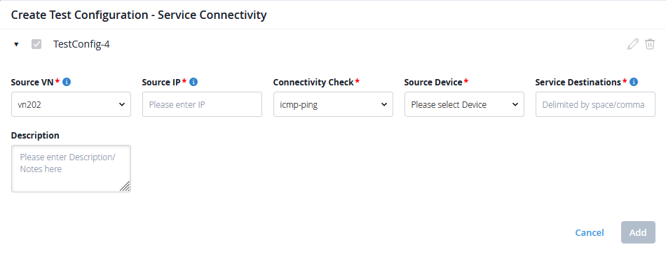
Enter the following details for the test config:
Table 1: Service Connectivity Test Config Field Description Test Config Name
A unique name for the test config.
The test config name can be up to 64 characters and can include letters, numbers, hyphens(-), and underscores(_).
Source VN
Select a source virtual network from the drop-down.
This is the overlay virtual network whose client-to-service connectivity you want to validate. The probe runs inside this VN's VRF, and follows the same data path and policies as client traffic.
Source IP
Enter an IP address for the source device.
The service connectivity test config requires an IP address from the selected source VN's subnet to mimic a client and act as the source IP address for the probe.
Note:You can configure only one source IP per Source VN on a given source device. The same source IP is reused for all probes originating from that VN on that source device. To ensure that this source IP address is not assigned to real clients in the network, configure the DHCP server to reserve individual IP addresses or a range of IP addresses.
Connectivity Check
Select the type of connectivity check you want to run:
http-get—Sends a Hypertext Transfer Protocol (HTTP) GET request to a target URL.
icmp-ping—Sends icmp echo requests to a target IP address.
Source Device
The leaf device from which the probe will be generated.
Select from a list of leaf devices available in the blueprint for the site.
Service Destinations
The service endpoint(s) that you want to test the reachability for. The destinations can be internal to the fabric or external services reached through the fabric.
For http-get, enter HTTP URLs. For example,
http://203.0.113.10:8080/healthFor icmp-ping, enter IPv4 addresses. For example,
203.0.113.10
You can add IP addresses for multiple services separated by commas in a single test config. A separate test case will be created for each individual service destination.
Description
A description of the test config for your reference.
Click Add.
You can create test configs for every combination of clients and services as per your requirements.
Deploy and Schedule Service Connectivity Test Configs
After creating test configs, you must save and deploy the test cases to the devices.
To deploy and schedule test configs:
Click the Select All check box on the top left of the page to select all the test configs for deployment.
Click Save on the top right of the page. A confirmation dialog box opens.
Click OK to proceed. The Save – Execution dialog box opens.
Figure 5: Save Execution for Service Connectivity Test Config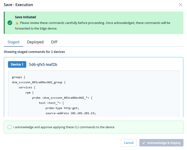
-
Use the following tabs to review the commands before deployment:
Staged—Displays the staged commands that will be added to all the devices for the selected test configs.
Deployed—Displays the test config commands currently active on all the devices.
Diff—Compares the deployed commands and the staged commands on all devices and highlights the updates made.
After reviewing the command updates, select the acknowledgment check box and click Acknowledge & Deploy.
The changes are pushed to the blueprint and the commands are deployed to the specific devices through Data Center Director. This deployment triggers the test configs to run a check immediately and schedules the test cases to run every hour going forward.
The status of the test config deployment will be displayed on the Save – Execution dialog box.
Note:You must stay on the Save – Execution dialog box to view the status of the test config deployment.
If the test config deployment returns a failure status, select the test configs and retry deployment.
If the test config deployment does not return a success or a failure status, reach out to Juniper Networks Technical Assistance Center (JTAC) for support.
View the results of the test configs on the Marvis Minis dashboard.
-
Every test config deployment updates the blueprint version. Repeated updates to the blueprints increase CPU and memory utilization. To optimize CPU and memory usage, deploy commands for multiple test configurations in a single operation. The Marvis Minis feature prompts you to select all test configurations to click the Save button and deploy the commands to devices.
-
When a deployment is in progress, you cannot create, modify, or delete any test configs on the blueprint.
-
If there are no new changes to apply, the acknowledgment check box and Acknowledge & Deploy are disabled.
Trigger an On-Demand Run for a Service Connectivity Test Config
Click Save whenever you add, modify, or delete test configs. Click Test Now only to trigger an on-demand run of already-deployed test configs.
To trigger a test config to run immediately:
Select the test config(s) you want to run.
Click Test Now on the top right of the page. A confirmation dialog box opens.
Click OK to proceed. The Test Now – Execution dialog box opens.
Triggering an on-demand run automatically makes a minor configuration change in the commands for the devices to activate the selected test configs.
Use the Staged, Deployed, and Diff tabs to review the command changes before proceeding with the deployment.
After reviewing the command updates, select the acknowledgment check box and click Acknowledge & Deploy.
This pushes the changes to the blueprint and triggers the selected test cases to run a check immediately.
View the status and results of the test configs on the Marvis Minis dashboard.
Fabric Connectivity Validation
Marvis Minis executes the fabric connectivity validation to verify that each leaf can successfully communicate with every other leaf within the data center fabric for a given overlay network. Marvis Minis verifies that all the virtual tunnel endpoint (VTEP) interfaces in a virtual network can reach one another by running the OAM probe overlay ping on source devices. For more information about overlay ping, see Understanding Overlay ping and Overlay traceroute Packet Support.
The ping mechanism ensures that transit nodes forward the OAM packets in the same way as a data packet for that particular overlay segment. This gives operators a precise view of whether the fabric is correctly transporting overlay traffic between VTEPs, rather than only checking for device availability.
The fabric connectivity test configs can only be run when the VTEPs in the overlay network that send and receive the overlay ping packets are Juniper Networks devices.
Create a Fabric Connectivity Test Config
To create a fabric connectivity test config:
On the Network Connectivity – Test Configuration page, select the Fabric Connectivity tab.
Figure 6: Test Configurations for Fabric Connectivity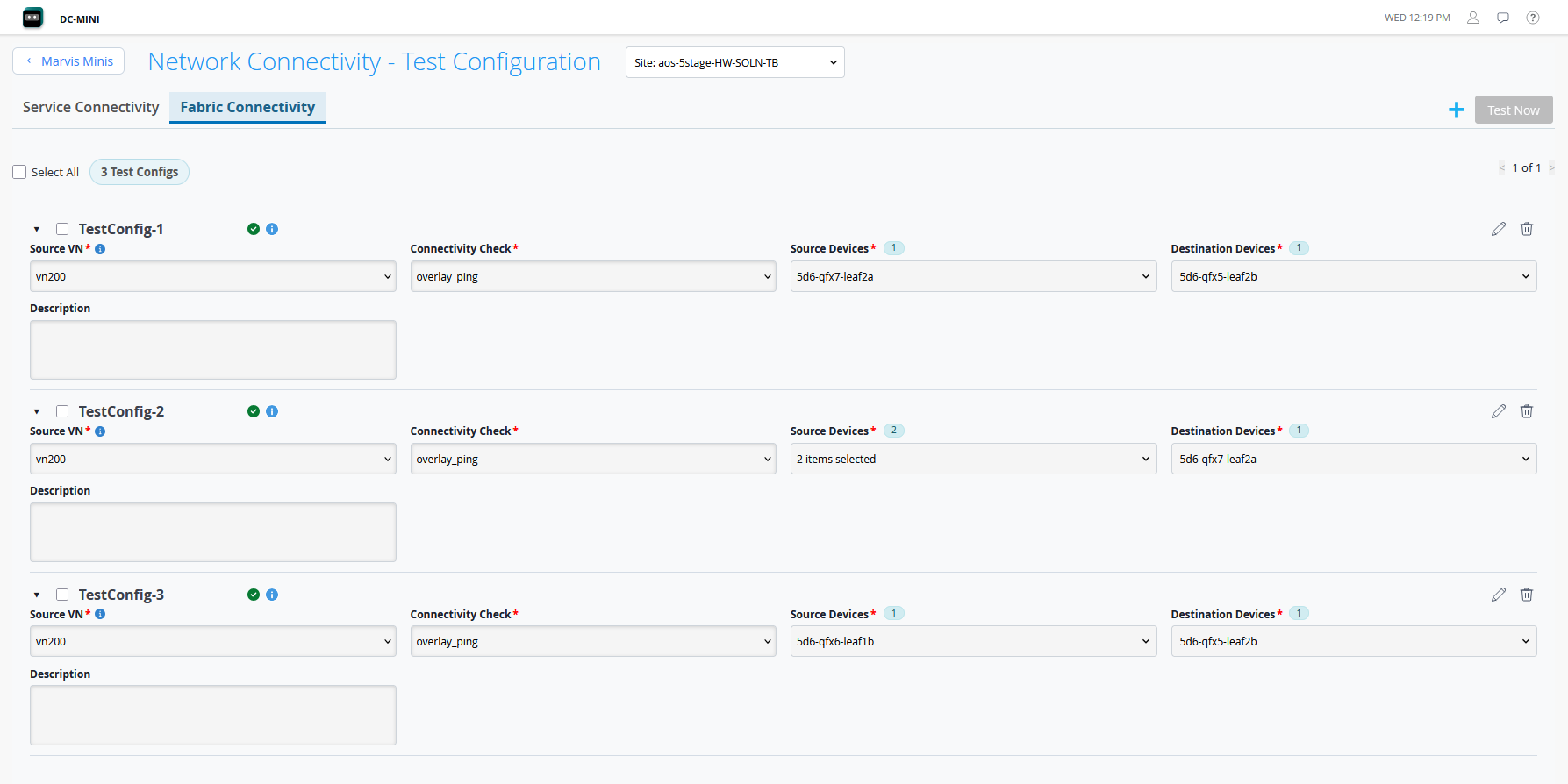
Click the "+" icon. The Create Test Configuration dialog box opens.
Figure 7: Create Test Configuration for Fabric Connectivity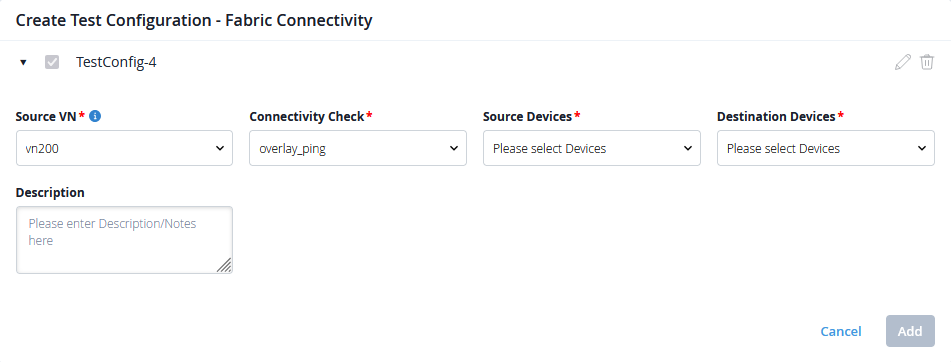
Enter the following details for the test config:
Table 2: Fabric Connectivity Test Config Field Description Test Config Name
A unique name for the test config.
The test config name can be up to 64 characters and can include letters, numbers, hyphens(-), and underscores(_).
Source VN
Select a source virtual network from the drop-down.
This is the overlay virtual network whose VTEP-to-VTEP connectivity you want to validate.
Connectivity Check
Select the type of connectivity check you want to run:
overlay-ping—Sends overlay ping packets as User Datagram Protocol (UDP) echo requests and replies that are encapsulated in the VXLAN header.
Source Devices
The leaf device whose VTEPs will initiate the overlay probes.
Select from a list of leaf devices available in the blueprint for the site.
Destination Devices
The destination device(s) whose VTEPs will be tested.
Select from a list of leaf devices available in the blueprint for the site. A separate test case will be created for each individual destination device.
Description
A description of the test config for your reference.
Click Add.
Deploy Fabric Connectivity Test Configs
After creating test configs as per your requirements, you must save and deploy the test cases to the blueprint.
To deploy and run fabric connectivity test configs:
Click the check boxes for all the test configs that you want to deploy.
Click Test Now on the top right of the page.
The changes are pushed to the blueprint and the commands are deployed to the specific devices through Data Center Director. This deployment triggers the test configs to run a check immediately and schedule test cases to run every hour going forward.
View the status and results of the test configs on the Marvis Minis dashboard.
Connectivity Checks Workflow
Service Connectivity Checks run in two phases:
-
The test configurations are deployed to the specific devices.
-
The test configurations are run in the network—first immediately after deployment, and again every hour.
Fabric Connectivity Checks have no device-configuration step. The checks run directly on the leaf VTEPs, on demand and on the hourly schedule.
To run the connectivity checks, Marvis Minis creates and manages a dedicated configlet and property set for each site in Data Center Director. We recommend that you create, modify, or remove test configs from the Marvis Minis page only. Editing or deleting the objects directly in Data Center Director can break the checks or leave stale configuration on the devices.