
Data Center Network Topologies on Data Center Assurance
A data center network consists of various components like servers and storage devices. Data center networking architecture refers to the design and organization of the network systems within a data center. A data center network must be designed to strike a balance between reliability, performance, agility, scalability and cost.
You can use the templates in Apstra Data Center Director to create a blueprint and design your data center network. For more information, see Create Blueprint in the Apstra Data Center Director User Guide.
HPE Mist Networking Data Center Assurance displays the data center network topologies on the Topology tab on the Dashboard page, the Service Topology View, and the Impact Analysis pages. Data Center Assurance also provides actionable insights about the device health and performance, events, and impacts of those events in a data center network.
Figure 1 shows the Overview tab on the Dashboard page. The various widgets provide information about the devices in the site(s), their role, anomalies in the network and so on.
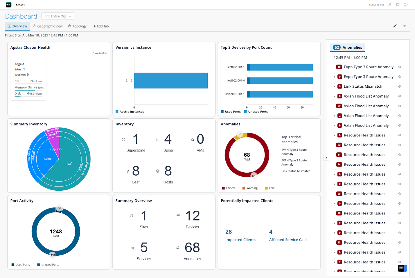
Figure 2 shows the Impact Analysis page with information about data center events and anomalies along with the impact of these anomalies on the data center network.
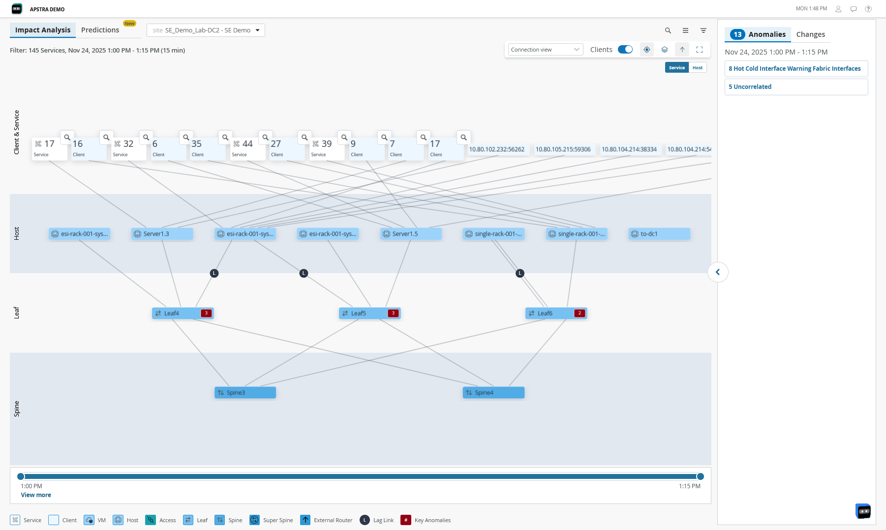
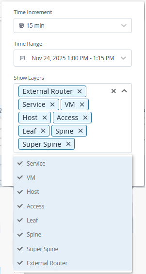
The network administrators use these insights to monitor the network and resolve issues to ensure that services are not impacted. Use the filters on the Service Topology View and Impact Analysis pages to select the layers to be displayed.
Currently, Data Center Assurance supports the following data center network architectures:
3-Stage Clos Architecture
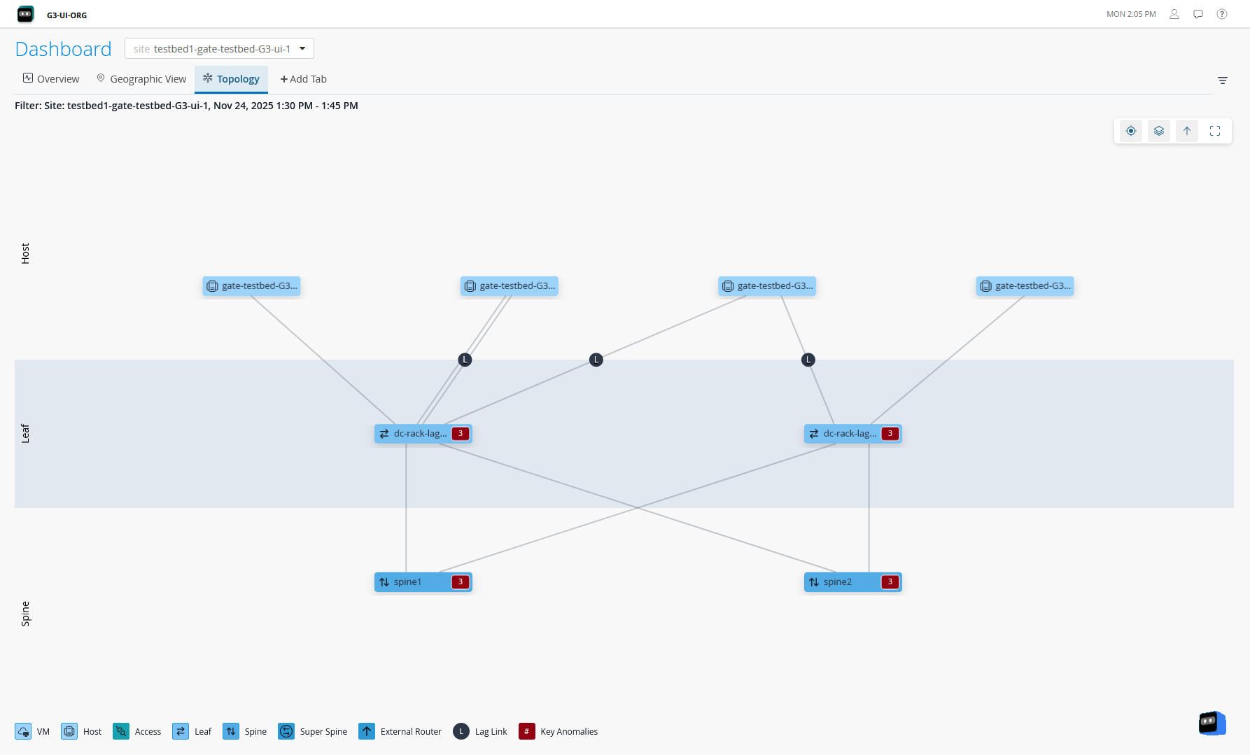
The 3-stage Clos Architecture provides organizations with a data center network that is fast, adaptable to change, scalable, and reliable. This topology consists of 3 components - server leaf switches, border leaf switches, and spine switches.
Data Center Assurance displays information and provides insights about the spines, leaf devices, hosts, and services in the data center network.
3-Stage Clos Architecture with Virtual Devices
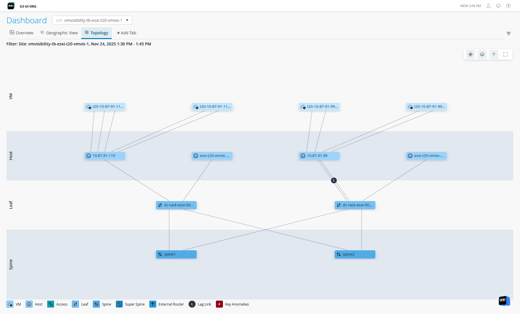
The 3-Stage Clos Architecture with Virtual Devices combines physical networks with network virtualization. This topology builds on a 3-stage fabric as the foundation for virtual network integration. In this design, the host layer is connected to different services through VMs.
Data Center Assurance collects information about the VMs in the data center and displays the VM layers in the topology views. To enable this feature, you must configure vCenter server on the Adopt Apstra Edge page. You can configure multiple vCenters.
Collapsed Data Center Fabric
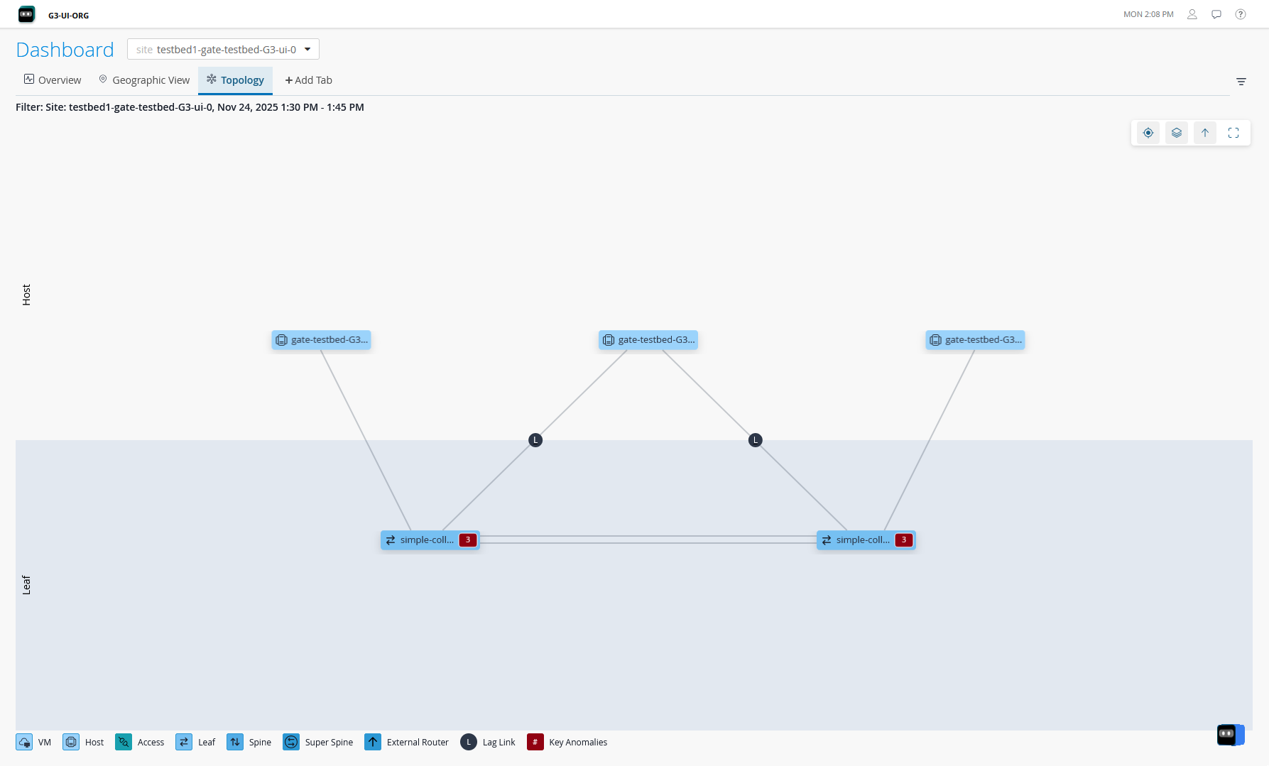
The collapsed data center fabric is a two-switch network fabric architecture designed for small network deployments. In collapsed fabric, switches perform the roles of spine, leaf, and border leaf switches. This design allows for high availability network deployments with minimum switch hardware. However, the hardware constraints limit the scalability of this architecture.
5-Stage Clos Architecture
The 5-stage Clos architecture is similar to the 3-stage data center design with the exception of a superspine layer. This design allows for scaling large scale data center design with requirements for large datastores and the compute nodes that need to connect to the data storage. In this topology, an additional layer of superspine devices interconnects multiple pods consisting of spine-and-leaf layers (similar to 3-Stage fabric), thus creating a large network.
Data Center Assurance displays information and provides insights about the superspine layer, spines, leaf devices, hosts, and services in the data center network.
Data Center Assurance currently does not support the display of pods.
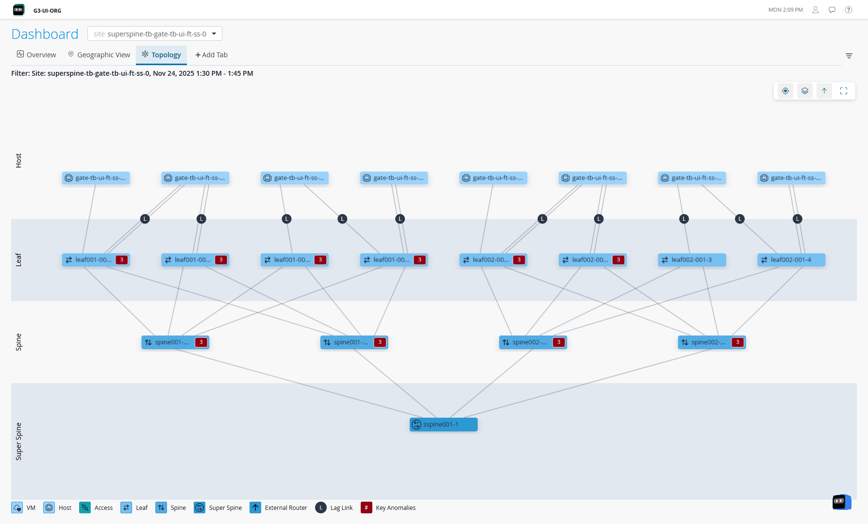
If your 5-Stage Clos fabric is rendered as a 3-Stage Clos fabric on Data Center Assurance, you must make a minor change in the site blueprint (for example, change the blueprint description) in Juniper Apstra Edge device. The data center network is rendered as a 5-Stage Clos fabric displaying the superspine layer after Data Center Assurance synchronizes data with the Edge device.
Network Architecture with Access Layer Support
Access switches connect end-user devices to the data center network. These switches also manage and direct data traffic to ensure that the packets are sent to the correct destination. Access layer switches make the data center networks more scalable, provide security to the network devices, and reduce operational complexity of the network by simplifying device connections.
Apstra supports access switch layer in 3-stage Clos, 5-stage Clos, and collapsed fabric network architecture. Data Center Assurance displays information about the health and status of the access switches in the network along with the other network components, thus helping prevent potential issues and manage network infrastructure.
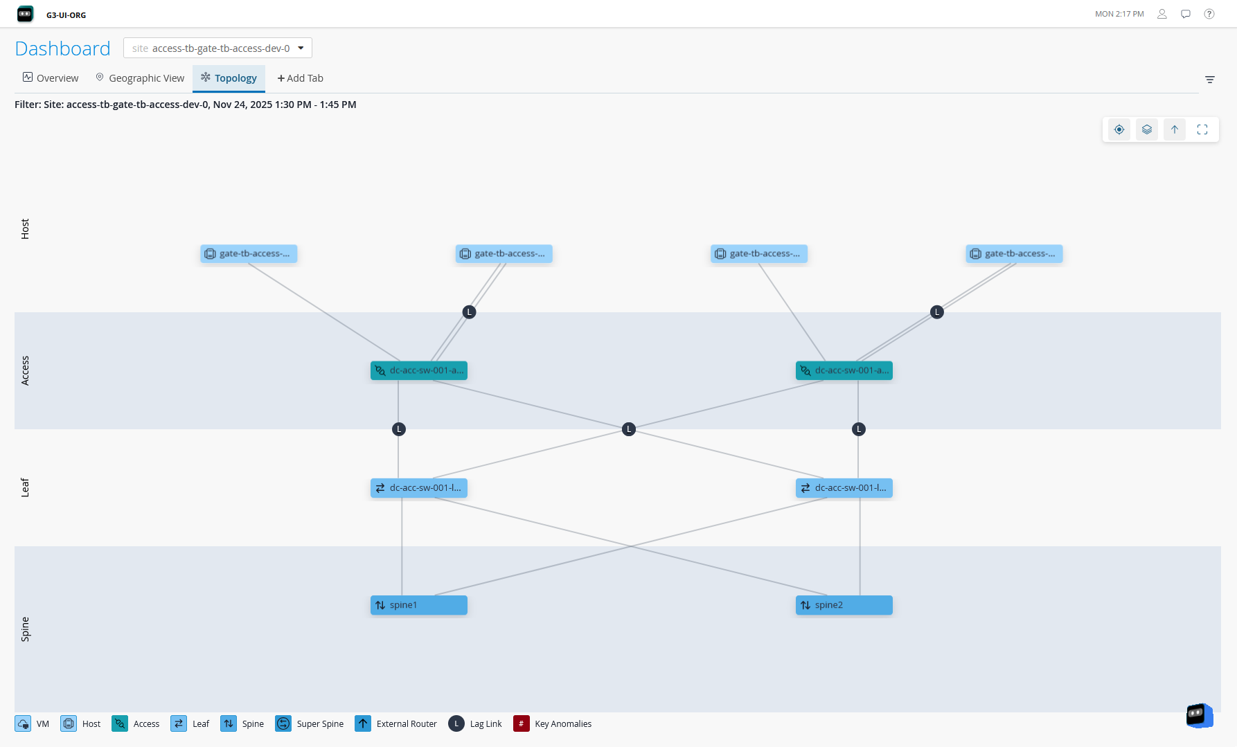
Data Center Assurance displays information only about Juniper devices on the access layer.
Network Architecture with External Router Support
Apstra allows you to connect your data center network to external systems that are not managed by Apstra. These systems are called External Generic Systems. These systems provide connectivity between two or more data centers as Data Center Interconnect (DCI) connections to share data and resources. The external systems can be firewalls, external routers, and so on. The external generic systems are not part of a rack topology and are typically connected to a border leaf. For more information, see Create External Generic System in the Apstra Data Center Director User Guide.
Data Center Assurance supports visualization of external routers connected to a border leaf of the data center network architecture and provides information about the health and status of the external router. It displays the data center clients for which the external router acts as a gateway and also displays flow data information between the data center and the external router. This information helps network administrators design data center networks and make informed decisions to optimize network operations.
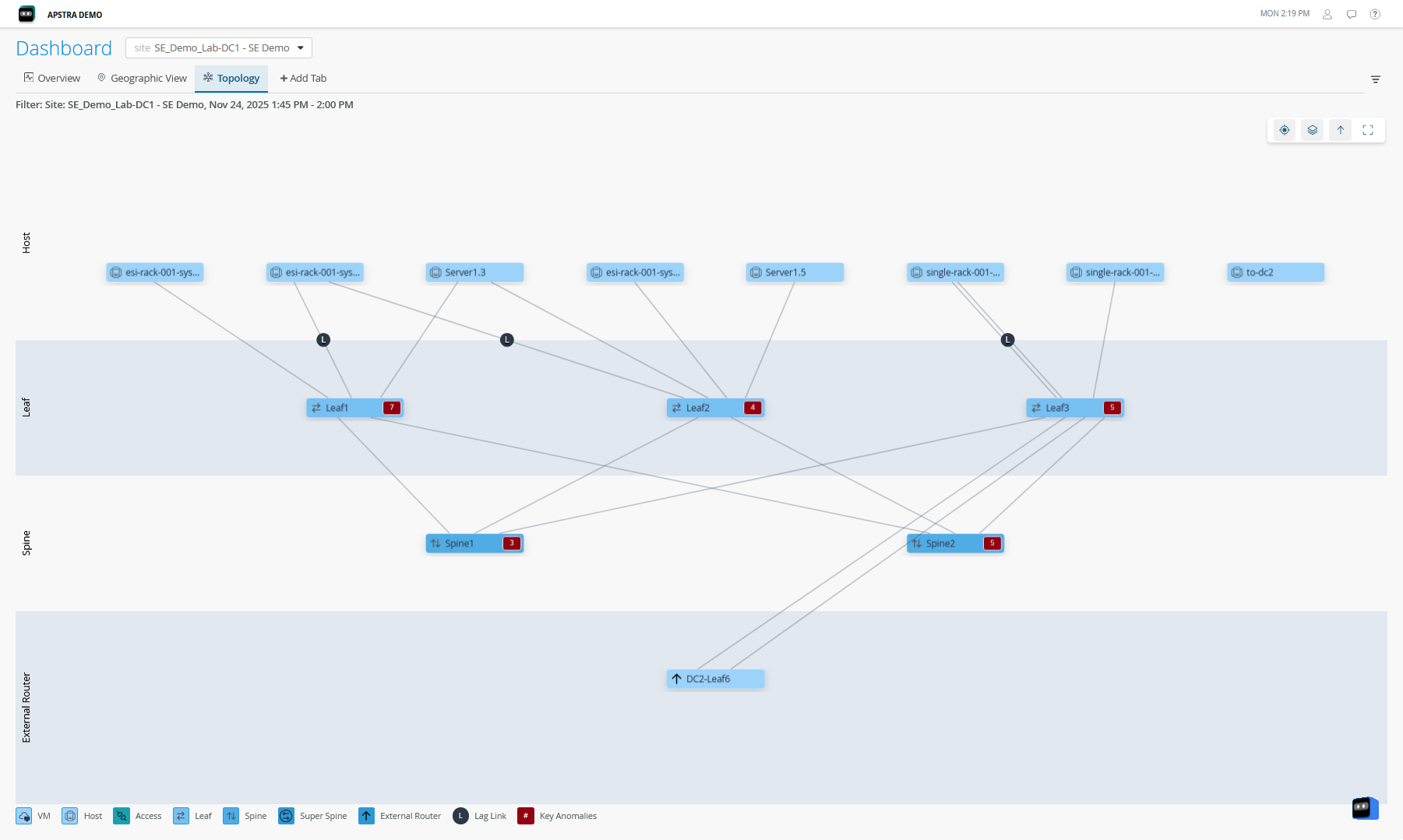
Since the external systems are not Apstra-managed, Data Center Assurance does not display metrics or anomaly data for the external routers.