Create Rack Type (L3 Clos)
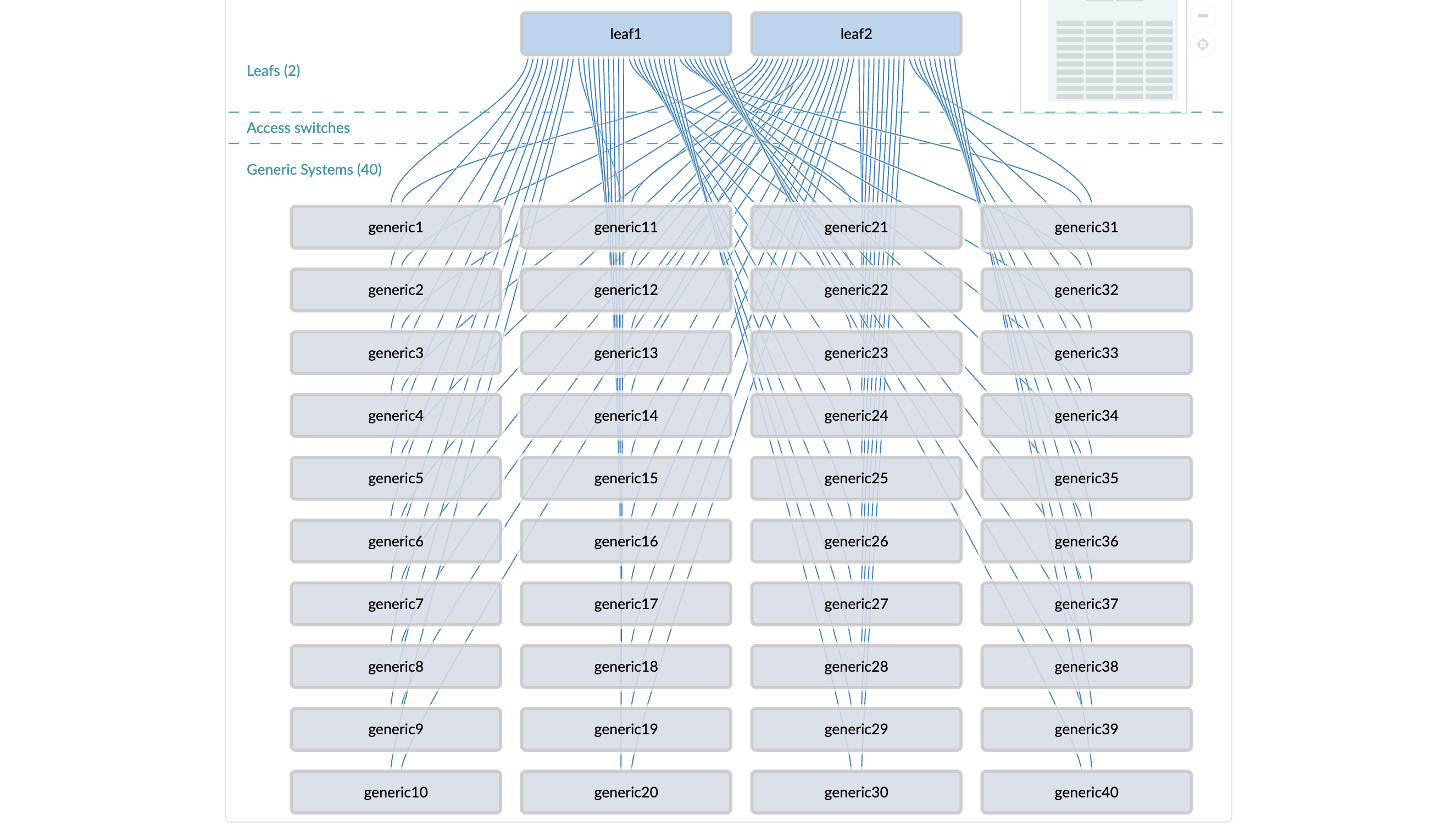
We'll demonstrate how to create a rack type for an L3 Clos rack with 2 Top-of-Rack (ToR) leaf switches with 40 servers connected to both switches.
When building rack types, you're basically assigning logical devices to leaf devices, (optional) access switches, and generic systems, then linking them.
When you're designing your own racks, consult the Design (global) catalog (Design > Logical Devices) to find a logical device with your planned configuration. If you don't find one, you can create your own.
Our example uses predefined logical devices, so we're ready to create our rack type, as shown in the screenshot below.
To create an L3 Clos rack type using the GUI:
-
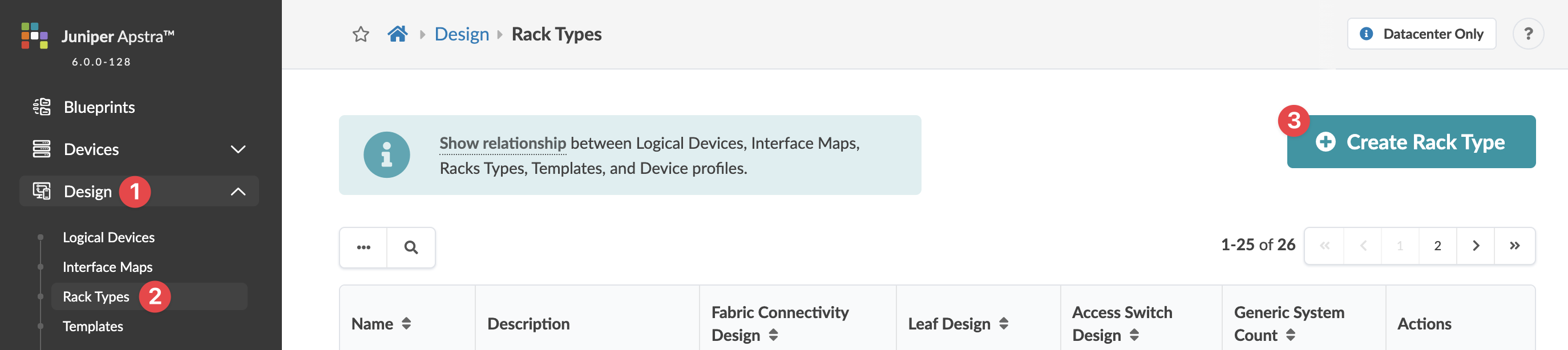
From the left navigation menu, navigate to Design > Rack
Types and click Create Rack Type (or to copy an
existing rack type and customize it, click the Clone button in the Actions
panel for the rack type to copy).
(Note: Rack Type Builder was deprecated in version 6.0.0.)
 The Create Rack Type dialog opens (or the Clone Rack Type dialog opens).
 -
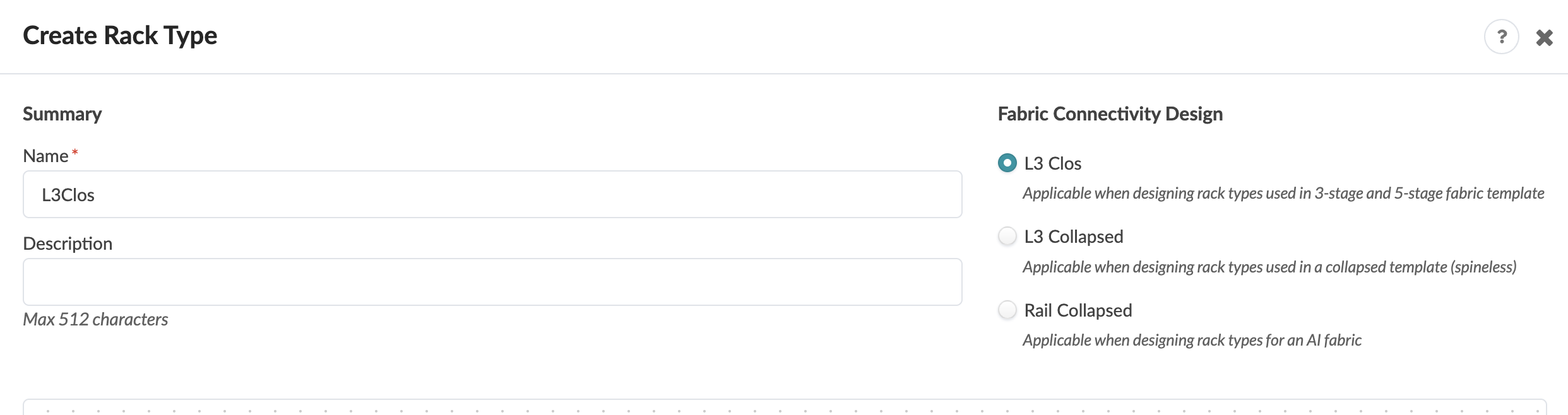
Enter Summary details.
Enter a unique rack type name (17 characters or fewer) and an (optional) description, then for Fabric Connectivity Design, select L3 Clos.
-
Create 2 leaf switches.
-
Click the Add Leaf button (in the bottom row of operations
buttons).
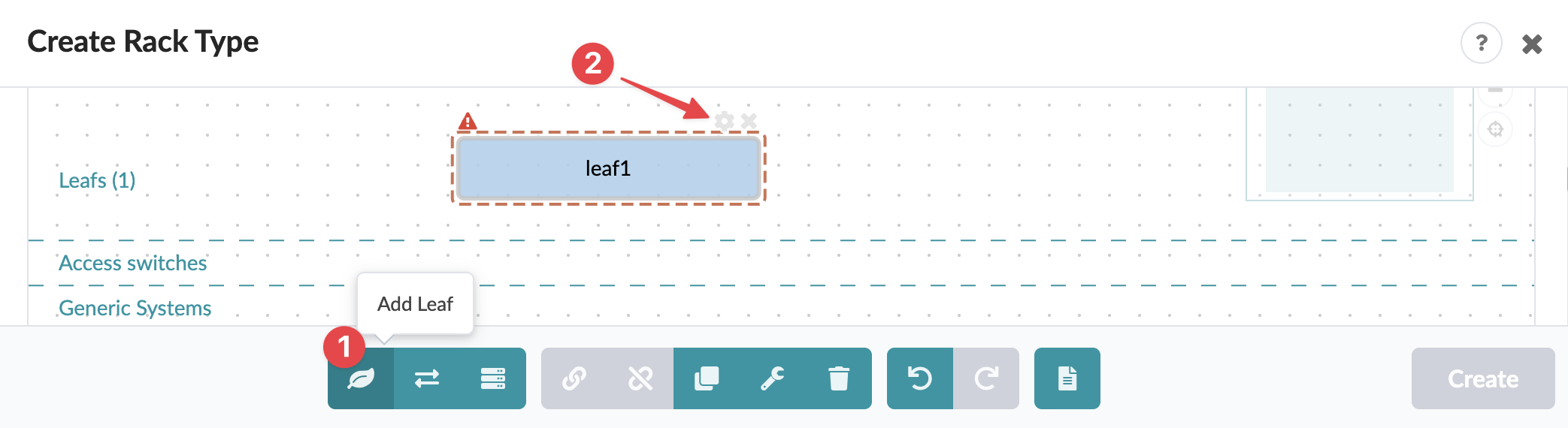
A graphical representation of the leaf appears with an initial default label of leaf1.
When a leaf is selected it has a red dashed border.
The red triangle in the upper left corner of the leaf indicates that required fields need information. Hover over the triangle to see that you need to specify a logical device. Links per spine automatically defaults to 1 when you select the logical device.
-
From the Logical Device drop-down list, select the appropriate logical
device for the Top-of-Rack (ToR) leaf switch.
Note:
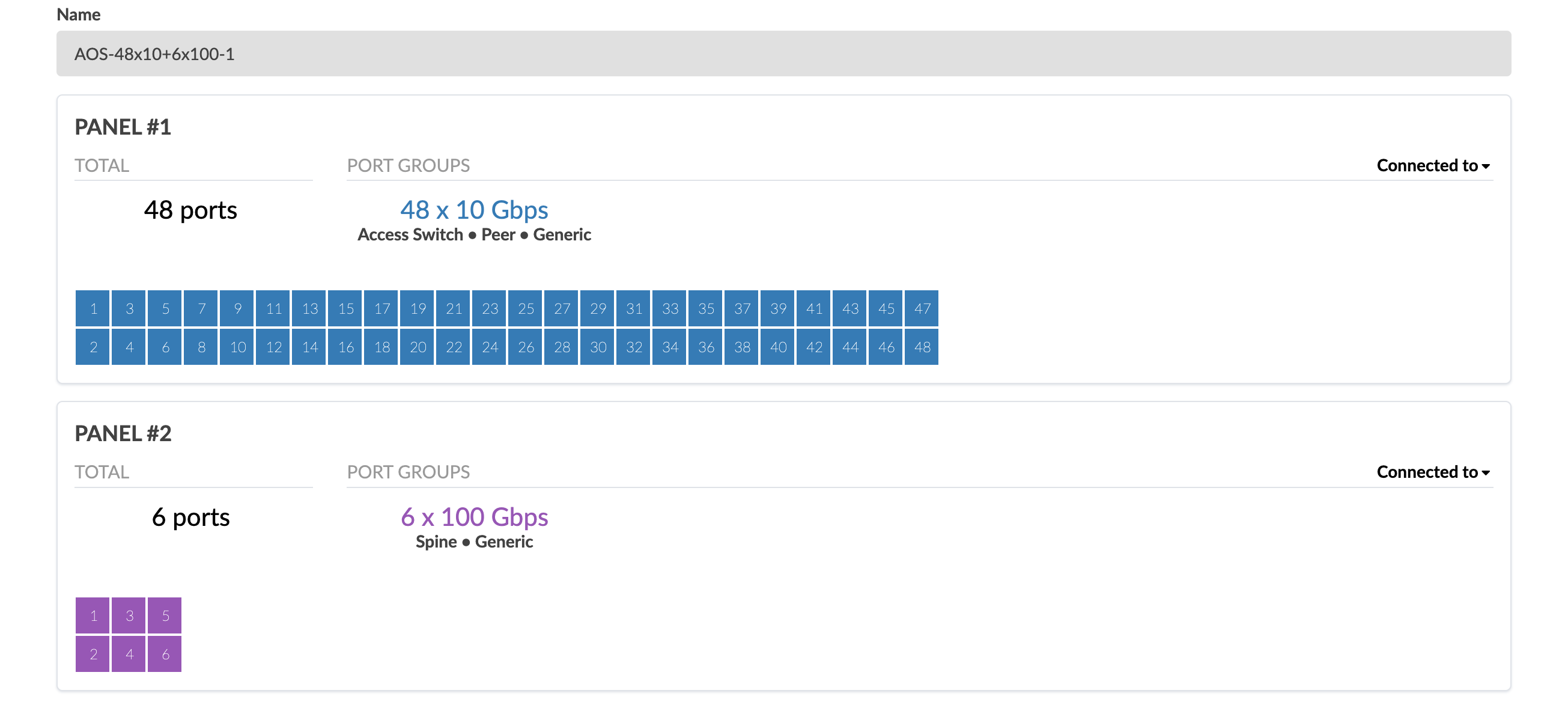
For our example, we need a device with at least 40 ports for our servers (generic systems) and 2 ports for connecting to spines for when we create the template later. We're using the predefined logical device AOS-48x10+6x100-1, which represents a device with 2 panels (port groups) with the following characteristics:
-
The first port group consists of 48 ports at 10 Gbps that can connect to an access switch, a peer, or a generic system. We'll be using 40 of the ports.
-
The second port group consists of 6 ports at 100 Gbps that can connect to a spine or a generic system. We'll be using 2 of the ports.
Since L3 Clos racks are connected to a spine, only logical devices that include a port with the spine role are included in the list. The list comes from the logical devices Design catalog (Design > Logical Devices), also known as the global catalog.
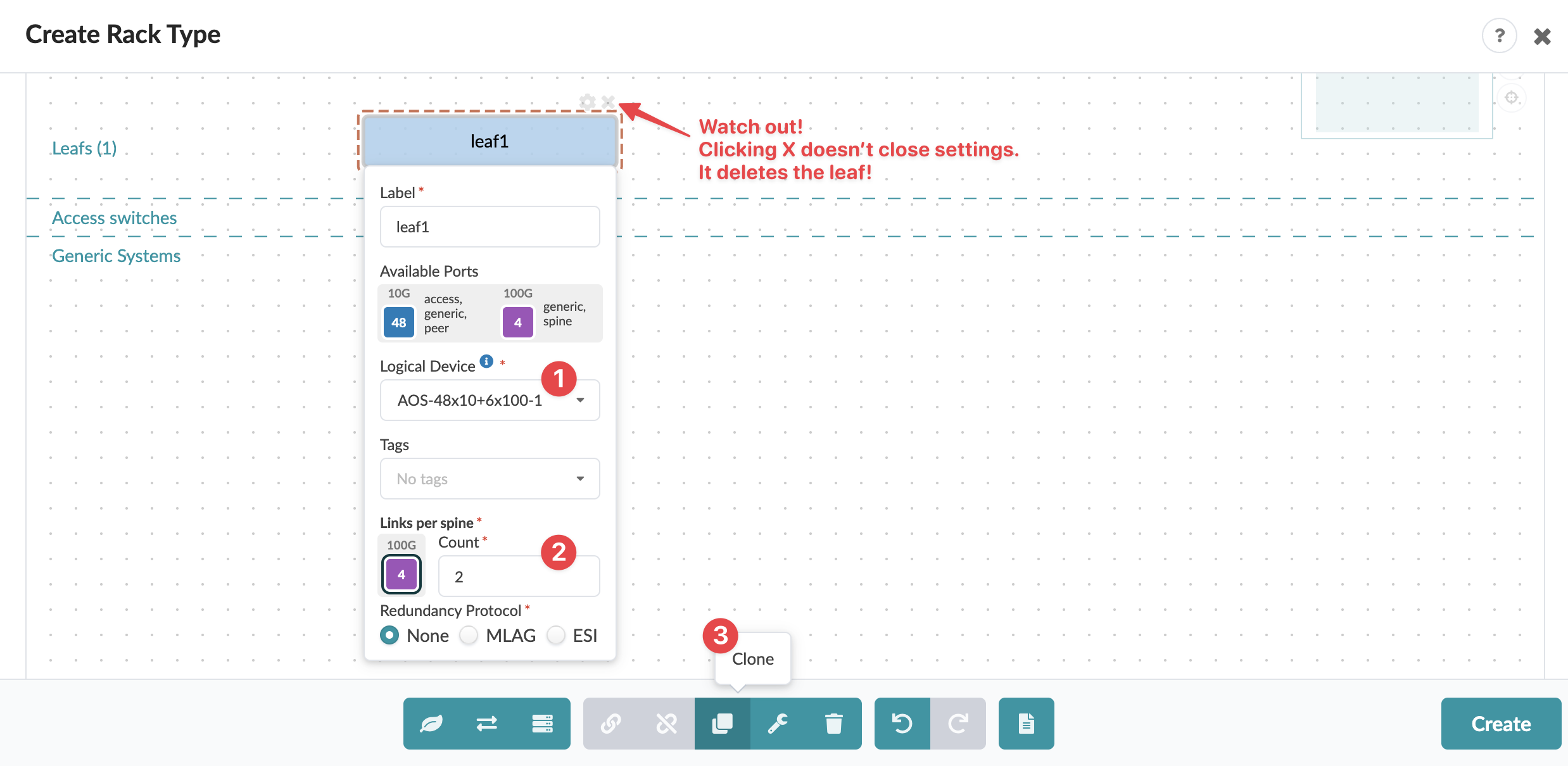
After you select the logical device, available ports and port roles appear in the Available Ports section based on the logical device details. Also, the number of ports that have the spine role appear in the Links per spine section. The value defaults to 1. In our example, we want to be able to link to 2 spines when we create the template
You can change any of the default Label values as you create your rack type.
The red triangle in the upper left corner of the leaf goes away since the requirements for a leaf have been satisfied.
-
-
Click the Add Leaf button (in the bottom row of operations
buttons).
-
Create a generic system.
-
Click the Add Generic Server button (in the bottom row of
operation buttons).
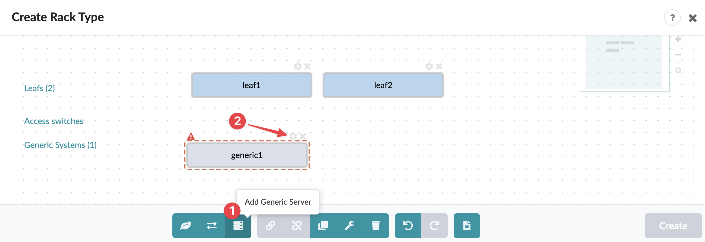
A graphical representation of the generic system appears with an initial default label of generic1.
When a generic system is selected it has a red dashed border.
The red triangle in the upper left corner of the system indicates that required fields need information. Hover over the triangle to see that the system needs to have a logical device specfied; it also needs to be connected to a leaf.
-
From the Logical Device drop-down list, select the appropriate logical
device for your servers.
Note:
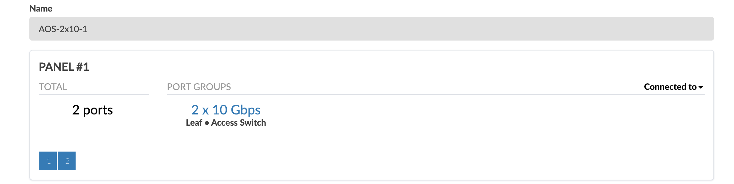
For our example, we're using the predefined logical device AOS-2x10⁻¹, which represents a device with 1 panel (port group) consisting of 2 ports at 10 Gbps that can connect to a leaf or an access switch.
Since generic systems must connect to a leaf (or access switch), only logical devices that include a port with the leaf (or access switch) role are included in the list. The list comes from the logical devices Design catalog (Design > Logical Devices), also known as the global catalog.
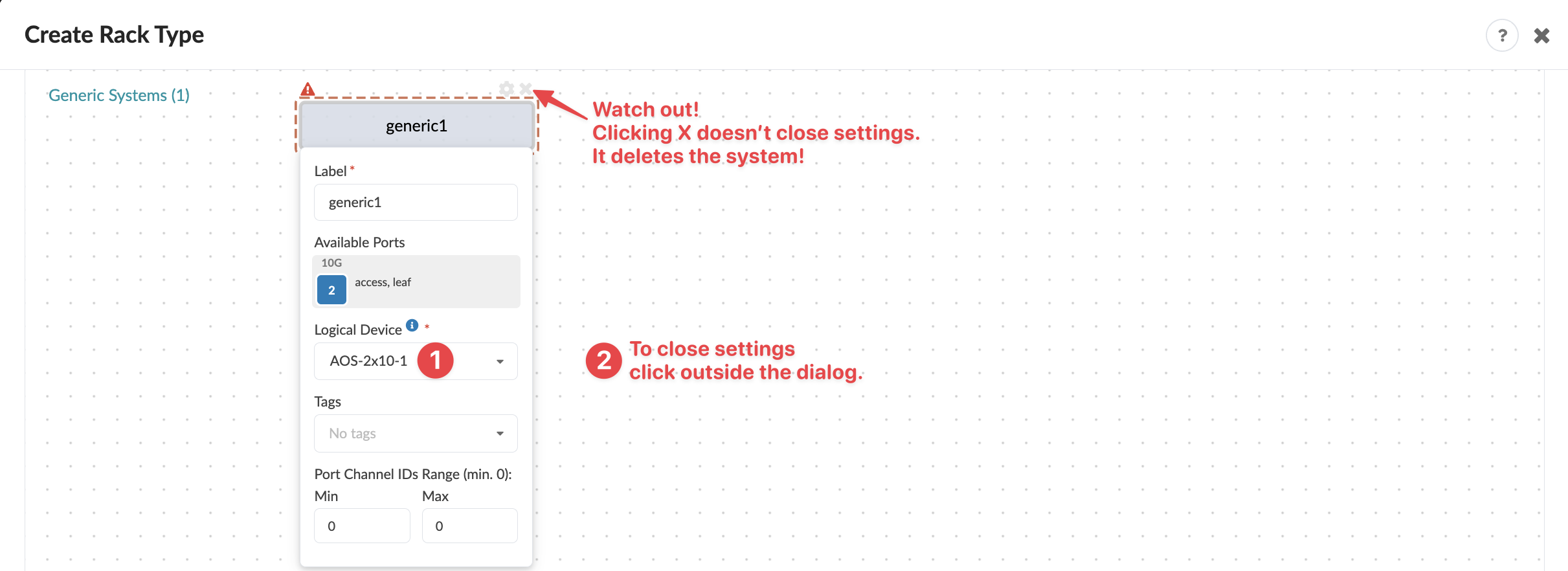
After you select the logical device, available ports and port roles appear in the Available Ports section based on the logical device details. We'll use those ports to connect to the leaf devices.
The red triangle in the upper left corner of the generic system remains since we still need to add links. Let's do that now.
-
Click the Add Generic Server button (in the bottom row of
operation buttons).
-
Link the generic system to the leaf devices.
-
Click and drag to select the 2 leaf devices and the generic system. (As soon as you
click outside the dialog, it closes.) Click the Managed Mutliple
Links button (in the bottom row of operation buttons), then click
Create.
 The dialog closes and the links are created.
 -
We want the LAG modes to be LACP Active, so let's open the link details and
change the LAG mode. Click on one of the links to open details, then select LACP
Active LAG mode and click outside the settings dialog. Repeat for the other
link.
 We now have 2 leafs connected to one generic system configured for our example.
-
Click and drag to select the 2 leaf devices and the generic system. (As soon as you
click outside the dialog, it closes.) Click the Managed Mutliple
Links button (in the bottom row of operation buttons), then click
Create.
-
Clone the generic system to create 40 systems.
Note:
The way you clone systems affects how they are positioned in the limited viewing area of the canvas. If you clone one system many times, the systems line up in one column, which, depending on the number of systems you've created, prevents you from seeing the entire topology without having to scroll.
A better way is to clone the system a few times to use the vertical space of the canvas, then clone those systems a few times to create the number of systems you want and to use the horizontal space. See below for how we do it with our example.
-
Click to select the generic system, click the Clone button 9
times, then select all 10 generic systems and click the Clone
button 3 times.
 40 generic systems have been generated that are linked to the 2 leaf devices.
-
Click to select the generic system, click the Clone button 9
times, then select all 10 generic systems and click the Clone
button 3 times.