Help us improve your experience.

Let us know what you think.

Do you have time for a two-minute survey?


Create a Device Profile and Assign an Interface Map to the SRX

This step is a Blueprint prerequisite that you must complete to run ConnectorOps. For other prerequisites, see Prerequisites.

You must create a Device Profile for the Juniper SRX because it is onboarded as a Generic System in Apstra. A Device Profile specifies ports and hardware capabilities.

To create a Device Profile and Assign an Interface Map to the SRX:

  1. Navigate to Devices > Device Profiles > Create Device Profile.

    The Create Device Profile window displays.

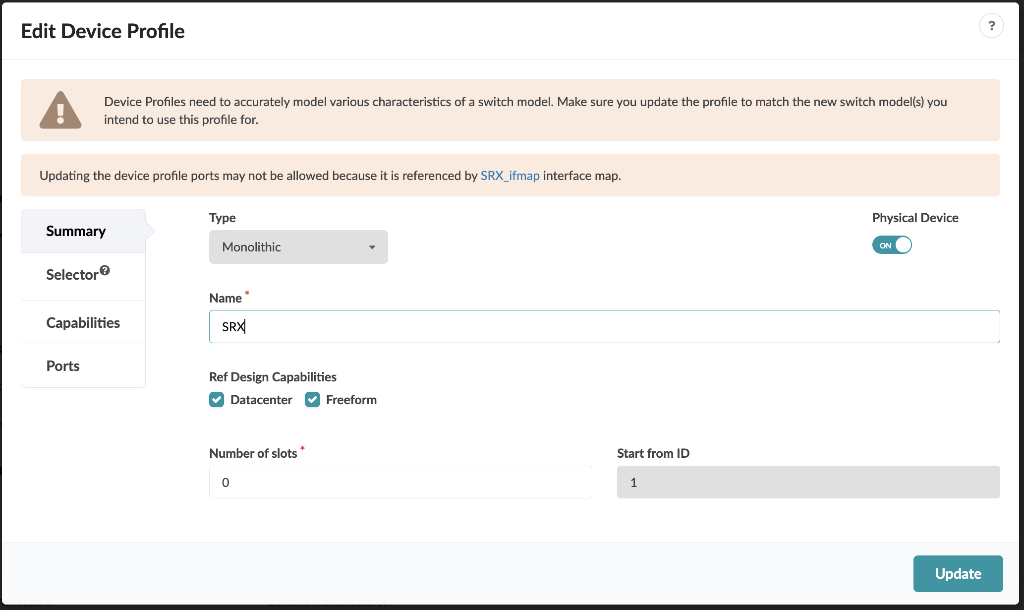
  2. For the Summary tab, choose a name for your SRX and mirror the settings in the following screenshot.

    Edit Device Profile interface with title, warning about accurate modeling and port updates, dropdown set to Monolithic, name field with SRX, physical device toggle ON, checked datacenter and freeform capabilities, slots set to 0, start ID set to 1, tabs for summary, selector, capabilities, ports, and Update button.
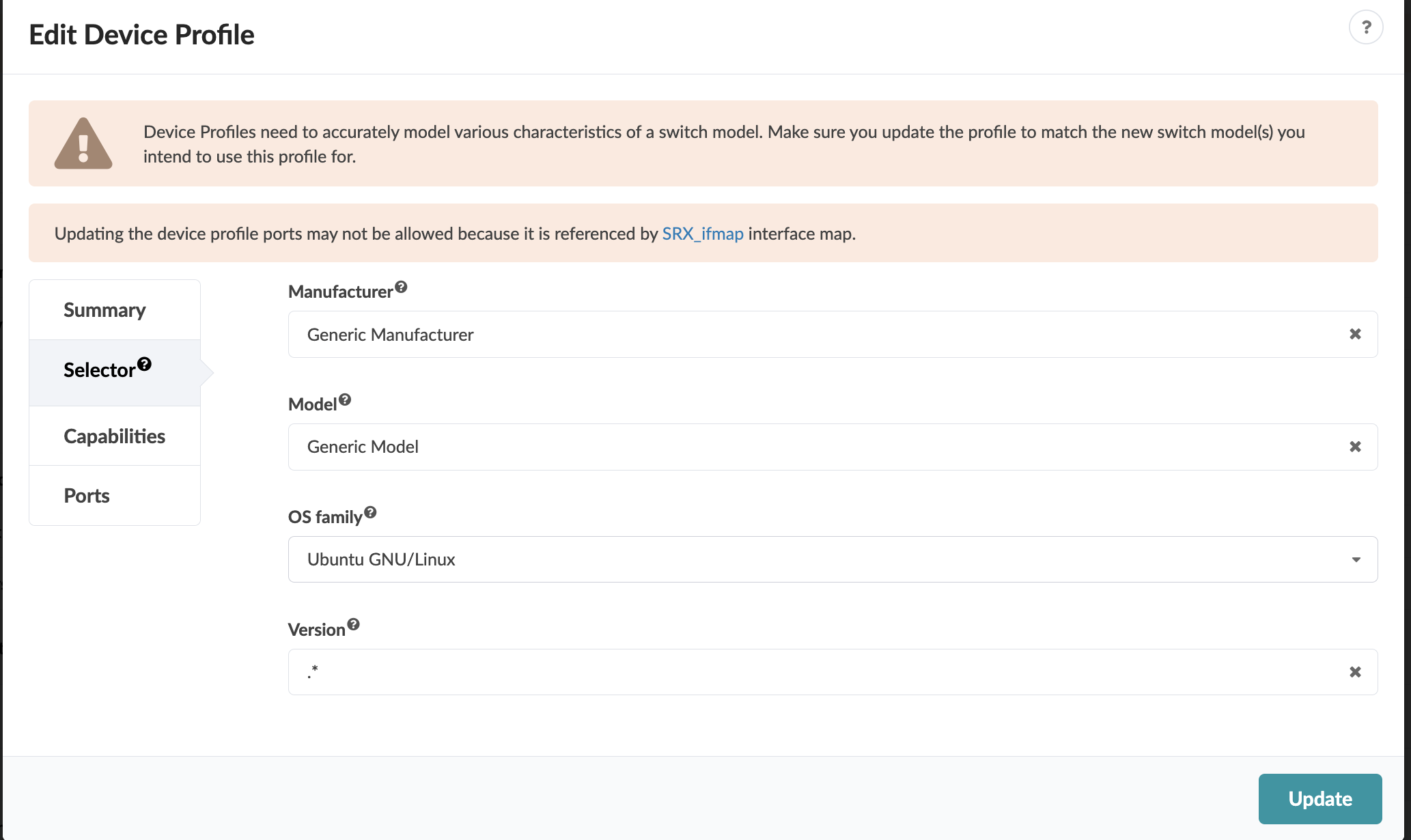
  3. For the Selector tab, mirror the settings in the following screenshot.

    User interface for editing a device profile with fields for Manufacturer, Model, OS family, and Version. Selected values: Generic Manufacturer, Generic Model, Ubuntu GNU/Linux, and any version. Includes warnings about ensuring the profile matches the switch model and restrictions on updating ports due to interface map reference SRX_ifmap. Navigation menu on the left with options like Summary, Selector, Capabilities, and Ports. Update button at the bottom right.
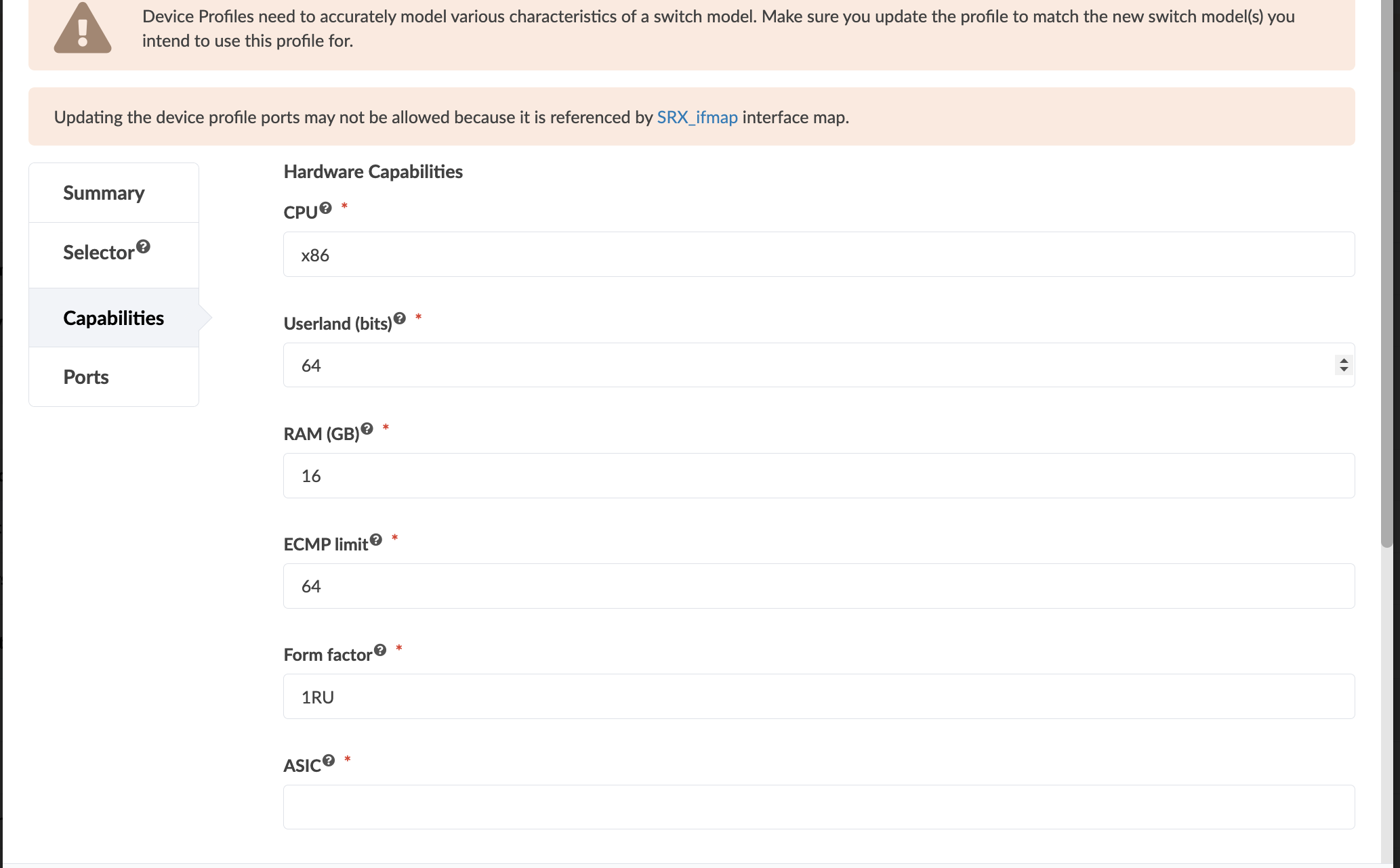
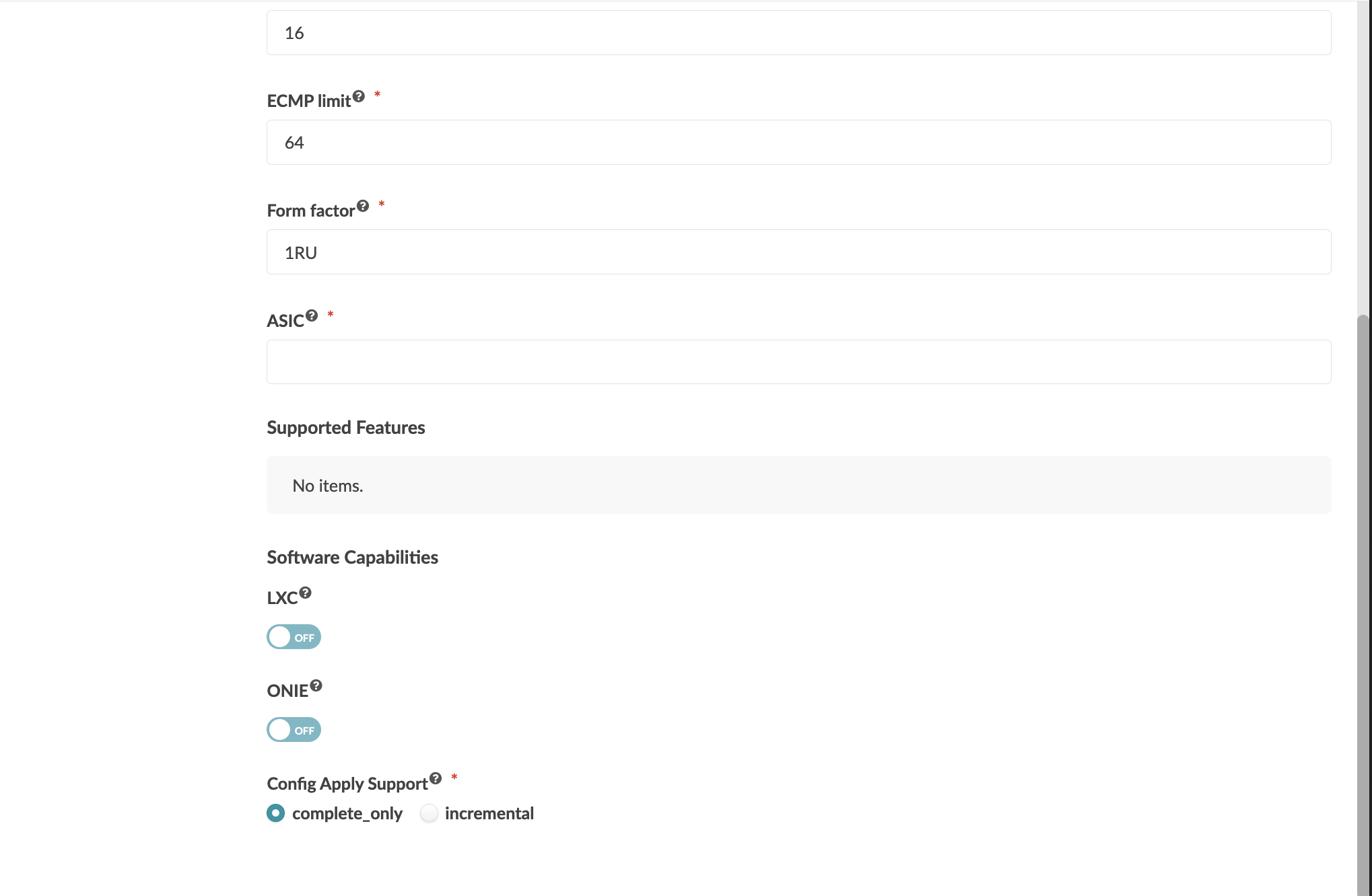
  4. For the Capabilities tab, mirror the settings in the following screenshots.

    Configuration interface for editing hardware capabilities of a device profile, including fields for CPU type, userland bits, RAM in GB, ECMP limit, form factor, and ASIC. Warnings about matching switch model characteristics and restrictions on updating device profile ports are displayed at the top.

    Network device form with ECMP limit set to 64, form factor 1RU, empty ASIC field, no supported features, software capabilities LXC and ONIE toggled off, and config apply support set to complete only.
  5. For the Ports tab, mirror the settings in the following screenshots.

    Configuration interface for managing network ports, showing port selection, display ID, connector type set to SFP, and transformations like speed set to 1 Gbps and interface ge-0/0/0.

    Configuration interface for managing network ports with options to select ports, set display ID, choose connector type, configure speed and interface, and access additional settings.
  6. Navigate to Design > Interface Maps > Create Interface Map.

    The Create Interface Map window displays.

  7. Select a Logical Device from the dropdown.
  8. Select the SRX Device Profile from the dropdown.
  9. Enter a name for the Interface Map.
  10. Under the Map interfaces section, click Select interfaces in the Device Profile Interfaces column.

    The interfaces of your Logical Device display.

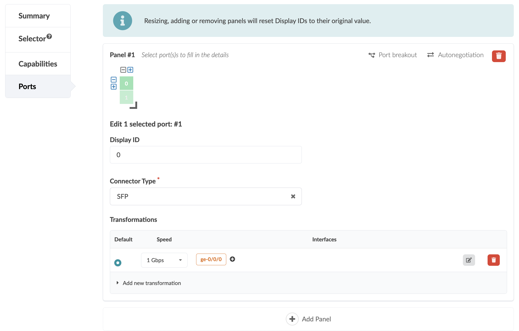
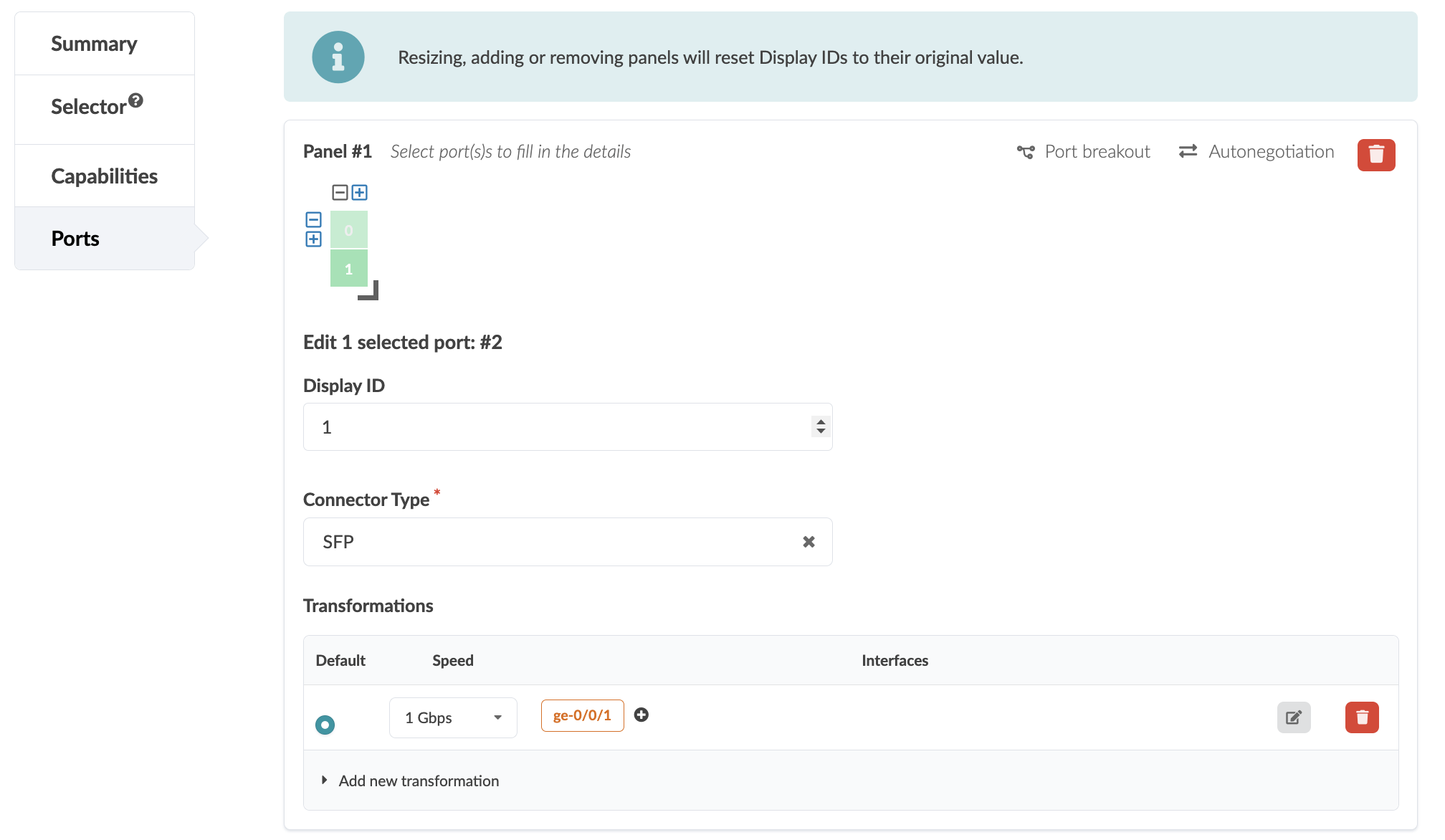
  11. Select each interface to map the port groups to their respective interfaces.

    User interface for creating an interface map in a network tool, showing dropdowns for logical device and device profile, a text field for map name, port group details including speed and connection type, interface mapping for two ports, a transformation applied, a preview section, and a create button.
  12. Click Create.
  13. From your Blueprint, navigate to Staged > Catalog > Interface Maps > Import Interface Map.

    The Import Interface Map from Global Catalog window displays.

  14. Select the Logical Device and Interface Map from the dropdowns.
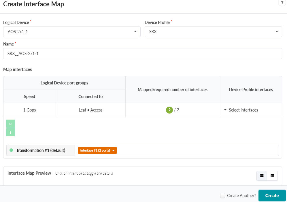
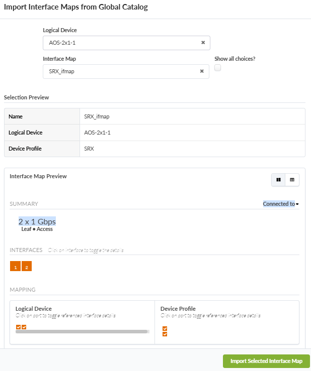
  15. Ensure that the mapped interfaces are correct and click Import Selected Interface Map.

    User interface for importing interface maps. Selected logical device: AOS-2x1-1. Interface map: SRX_ifmap. Details: 2 x 1 Gbps, Leaf + Access. Green button: Import Selected Interface Map.
  16. From the Blueprint, navigate to Physical > Topology view.
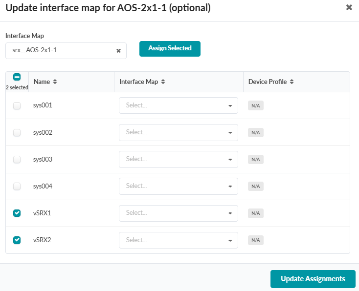
  17. In the Build view, select Device Profiles > Change interface map assignments for the logical device you created.

    User interface for updating the interface map for AOS-2x1-1 with a table listing system names, dropdowns for interface map selection, device profiles marked as N/A, and an Update Assignments button.
  18. Select the SRXs, then select the Interface Map from the dropdown and click Assign Selected.
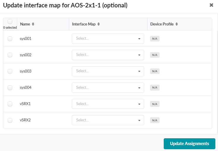
  19. Click Update Assignments.

    User interface for updating interface map for AOS-2x1-1, showing systems with checkboxes. vSRX1 and vSRX2 are selected. Dropdowns available for Interface Map and Device Profile. Buttons for Assign Selected and Update Assignments.
    The SRX has an assigned Device Profile and Interface Map. You can view the links and interface names in the Topology view.

    Network topology visualization showing vSRX1 connected to borderleaf1 and borderleaf2 with interface details.

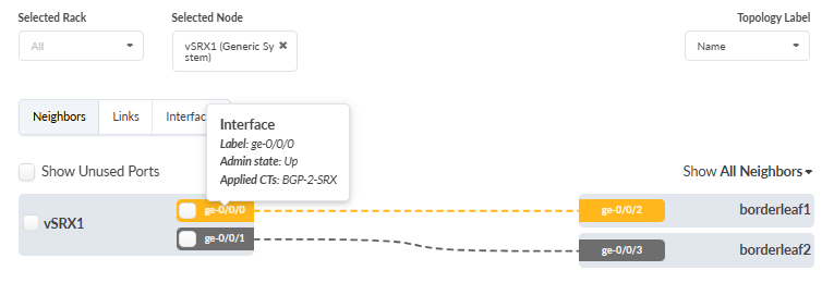
If you are setting up one of the Supported Topologies, ensure that the other Prerequisites are complete and proceed to Deploy Apstra ConnectorOps and Verify Connectivity.

For information about how to set up the example topology used in this guide, see Set Up the Example ConnectorOps Topology.