ON THIS PAGE
Set Up the Example ConnectorOps Topology
Use the following steps to set up the exact topology used in this Apstra ConnectorOps Setup Guide. There are many ways to configure the routing and design of your fabric, and this is just one example. All the configurations done in this process are specific to this topology.
If you are using your own topology, see the Prerequisites for everything ConnectorOps needs to render SRX configurations in Apstra. High-level steps:To Create a Routing Policy for Your Fabric
-
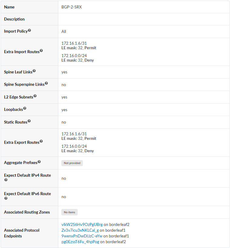
Configure your Routing Policy with the following parameters:
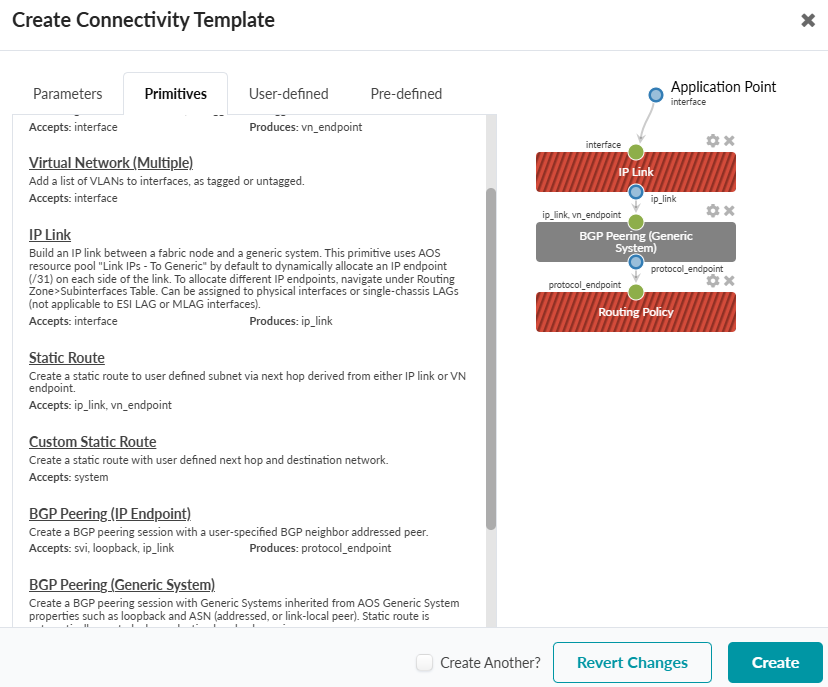
To Create and Assign a Connectivity Template Between the SRXs and Border Leaves
-
Select IP Link, BGP Peering (Generic System), and Routing
Policy.
-
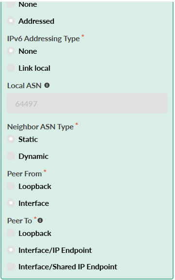
Select the Parameters tab and configure each primitive with the
following parameters:
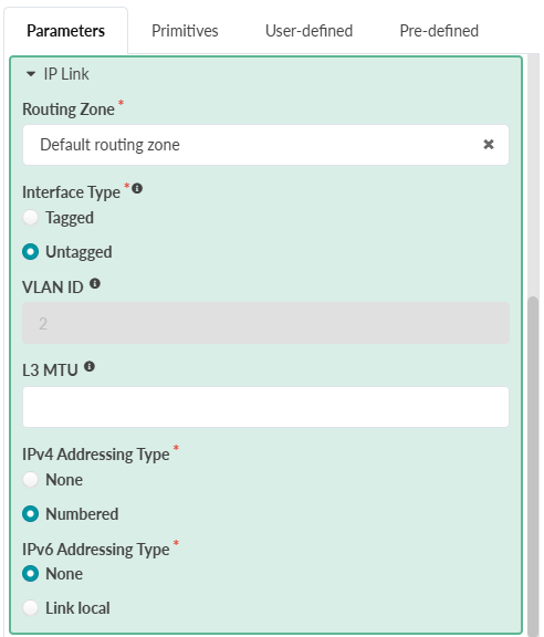
-
IP Link
-
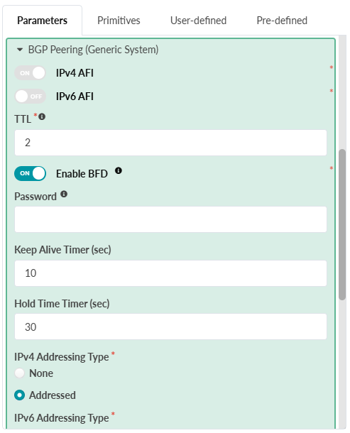
BGP Peering (Generic System)
-
Routing Policy: Your Routing Policy
-
-
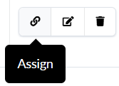
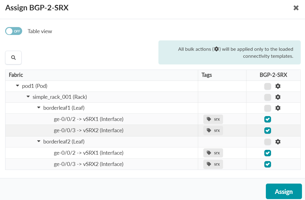
Select your Connectivity Template and click the Assign button.
-
Click Assign.
You can verify the new BGP peers by navigating to Staged > Virtual > Routing Zones > select default Routing Zone > Interfaces section.'
-
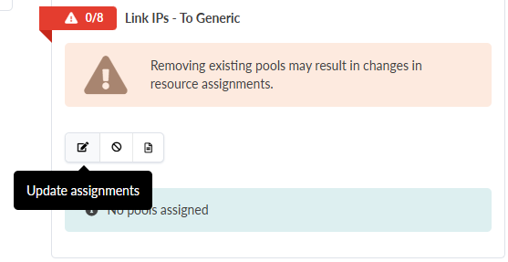
Assign Link IPs to Generic Systems
You can verify in Staged > Virtual > Protocol Sessions.
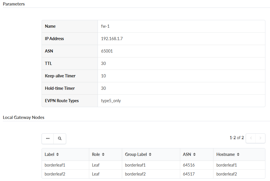
To Create External (Over the Top) Gateways in Apstra, and Designate them as Firewalls for Each SRX
-
2. Configure an external gateway for each SRX, with the following
parameters:
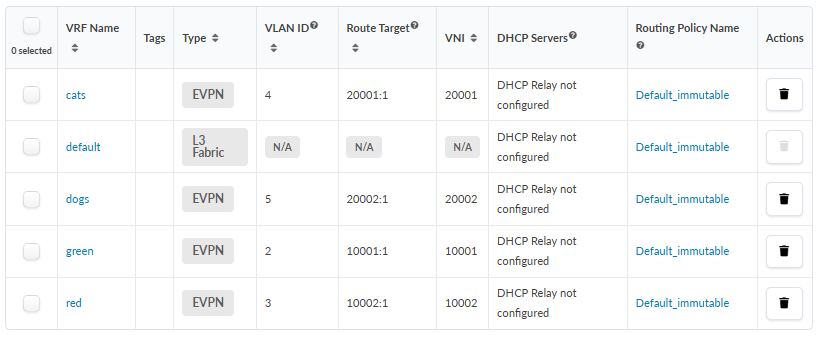
To Create VNs and Assign Routing Zones to Nodes
-
Repeat this process until A list of Routing Zones displays. The following
is an example list of Routing Zones.
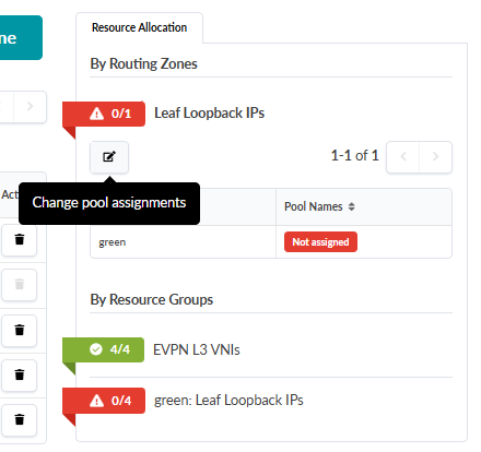
-
Click the Assign button to assign an IP pool for Loopback IP
addressing.
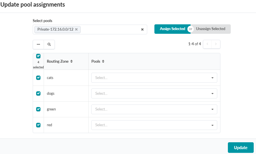
-
Select Assign Selected, then click Update.
-
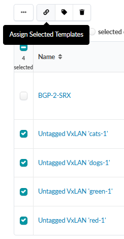
Select the new VNs from the list, and select the Assign Selected Templates
button at the top.
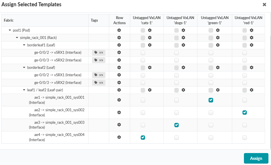
The Assign Selected Templates window displays. Note the columns for each VN at the top of the table.
-
Assign each VN to a corresponding interface (endpoint).
The following example shows the designated VN assignments.
To Configure Security Policies
The following are the exact Security Policies applied on the SRX devices in this example topology for end-to-end routing.
set groups COMMON security address-book global address FW-1 172.16.1.6/32
set groups COMMON security address-book global address FW-2-lo 172.16.1.7/32
set groups COMMON security address-book global address FW-2-ge-0-0-0 192.168.0.19/32
set groups COMMON security address-book global address FW-2-ge-0-0-1 192.168.0.23/32
set groups COMMON security address-book global address BGP-0 172.16.0.4/32
set groups COMMON security address-book global address BGP-1 172.16.0.5/32
set groups COMMON security address-book global address green 210.210.0.0/16
set groups COMMON security address-book global address red 200.200.0.0/16
set groups COMMON security address-book global address cats 221.221.0.0/16
set groups COMMON security address-book global address dogs 220.220.0.0/16
set groups COMMON security address-book global address-set FW-2 address FW-2-lo
set groups COMMON security address-book global address-set FW-2 address FW-2-ge-0-0-0
set groups COMMON security address-book global address-set FW-2 address FW-2-ge-0-0-1
set groups COMMON security policies from-zone evpn to-zone evpn policy HA-ICL match source-address FW-2
set groups COMMON security policies from-zone evpn to-zone evpn policy HA-ICL match destination-address FW-1
set groups COMMON security policies from-zone evpn to-zone evpn policy HA-ICL match application any
set groups COMMON security policies from-zone evpn to-zone evpn policy HA-ICL then permit
set groups COMMON security policies from-zone evpn to-zone evpn policy HA-ICL then log session-init
set groups COMMON security policies from-zone evpn to-zone evpn policy HA-ICL then log session-close
set groups COMMON security policies from-zone evpn to-zone evpn policy G2R match source-address green
set groups COMMON security policies from-zone evpn to-zone evpn policy G2R match destination-address red
set groups COMMON security policies from-zone evpn to-zone evpn policy G2R match application junos-ping
set groups COMMON security policies from-zone evpn to-zone evpn policy G2R match application junos-ssh
set groups COMMON security policies from-zone evpn to-zone evpn policy G2R match source-l3vpn-vrf-group GREEN
set groups COMMON security policies from-zone evpn to-zone evpn policy G2R match destination-l3vpn-vrf-group RED
set groups COMMON security policies from-zone evpn to-zone evpn policy G2R then permit
set groups COMMON security policies from-zone evpn to-zone evpn policy G2R then log session-init
set groups COMMON security policies from-zone evpn to-zone evpn policy G2R then log session-close
set groups COMMON security policies from-zone evpn to-zone evpn policy R2G match source-address red
set groups COMMON security policies from-zone evpn to-zone evpn policy R2G match destination-address green
set groups COMMON security policies from-zone evpn to-zone evpn policy R2G match application junos-http
set groups COMMON security policies from-zone evpn to-zone evpn policy R2G match application junos-ping
set groups COMMON security policies from-zone evpn to-zone evpn policy R2G match source-l3vpn-vrf-group RED
set groups COMMON security policies from-zone evpn to-zone evpn policy R2G match destination-l3vpn-vrf-group GREEN
set groups COMMON security policies from-zone evpn to-zone evpn policy R2G then permit
set groups COMMON security policies from-zone evpn to-zone evpn policy R2G then log session-init
set groups COMMON security policies from-zone evpn to-zone evpn policy R2G then log session-close
set groups COMMON security policies from-zone evpn to-zone evpn policy D2C match source-address dogs
set groups COMMON security policies from-zone evpn to-zone evpn policy D2C match destination-address cats
set groups COMMON security policies from-zone evpn to-zone evpn policy D2C match application any
set groups COMMON security policies from-zone evpn to-zone evpn policy D2C match source-l3vpn-vrf-group DOGS
set groups COMMON security policies from-zone evpn to-zone evpn policy D2C match destination-l3vpn-vrf-group CATS
set groups COMMON security policies from-zone evpn to-zone evpn policy D2C then permit
set groups COMMON security policies from-zone evpn to-zone evpn policy C2D match source-address cats
set groups COMMON security policies from-zone evpn to-zone evpn policy C2D match destination-address dogs
set groups COMMON security policies from-zone evpn to-zone evpn policy C2D match application junos-ping
set groups COMMON security policies from-zone evpn to-zone evpn policy C2D match source-l3vpn-vrf-group CATS
set groups COMMON security policies from-zone evpn to-zone evpn policy C2D match destination-l3vpn-vrf-group DOGS
set groups COMMON security policies from-zone evpn to-zone evpn policy C2D then permit
set groups COMMON security policies from-zone evpn to-zone evpn policy FINAL-EVPN-DENY match source-address any
set groups COMMON security policies from-zone evpn to-zone evpn policy FINAL-EVPN-DENY match destination-address any
set groups COMMON security policies from-zone evpn to-zone evpn policy FINAL-EVPN-DENY match application junos-vxlan
set groups COMMON security policies from-zone evpn to-zone evpn policy FINAL-EVPN-DENY then deny
set groups COMMON security policies from-zone evpn to-zone evpn policy infra description "control plane permit"
set groups COMMON security policies from-zone evpn to-zone evpn policy infra match source-address any
set groups COMMON security policies from-zone evpn to-zone evpn policy infra match destination-address any
set groups COMMON security policies from-zone evpn to-zone evpn policy infra match application junos-bgp
set groups COMMON security policies from-zone evpn to-zone evpn policy infra match application junos-ping
set groups COMMON security policies from-zone evpn to-zone evpn policy infra match application bfd-mhop
set groups COMMON security policies from-zone evpn to-zone evpn policy infra then permit
set groups COMMON security policies from-zone evpn to-zone evpn policy infra then log session-init
set groups COMMON security policies from-zone evpn to-zone evpn policy infra then log session-close
set groups COMMON security policies from-zone evpn to-zone untrust policy C2EXT match source-address cats
set groups COMMON security policies from-zone evpn to-zone untrust policy C2EXT match destination-address any
set groups COMMON security policies from-zone evpn to-zone untrust policy C2EXT match application junos-http
set groups COMMON security policies from-zone evpn to-zone untrust policy C2EXT match application junos-http-ext
set groups COMMON security policies from-zone evpn to-zone untrust policy C2EXT match application junos-https
set groups COMMON security policies from-zone evpn to-zone untrust policy C2EXT match application junos-dns-udp
set groups COMMON security policies from-zone evpn to-zone untrust policy C2EXT match application junos-dns-tcp
set groups COMMON security policies from-zone evpn to-zone untrust policy C2EXT match application junos-ping
set groups COMMON security policies from-zone evpn to-zone untrust policy C2EXT match source-l3vpn-vrf-group CATS
set groups COMMON security policies from-zone evpn to-zone untrust policy C2EXT then permit
set groups COMMON security policies global policy infra-reject-log description "final touch"
set groups COMMON security policies global policy infra-reject-log match source-address any
set groups COMMON security policies global policy infra-reject-log match destination-address any
set groups COMMON security policies global policy infra-reject-log match application any
set groups COMMON security policies global policy infra-reject-log then reject
set groups COMMON security policies global policy infra-reject-log then log session-init
set groups COMMON security policies global policy infra-reject-log then log session-close
set groups COMMON security l3vpn vrf-group GREEN vrf GREEN
set groups COMMON security l3vpn vrf-group RED vrf RED
set groups COMMON security l3vpn vrf-group CATS vrf CATS
set groups COMMON security l3vpn vrf-group DOGS vrf DOGS
set security policies pre-id-default-policy then log session-close
set security zones security-zone trust tcp-rst
set security zones security-zone untrust screen untrust-screen
set security zones security-zone evpn host-inbound-traffic system-services all
set security zones security-zone evpn host-inbound-traffic protocols all
set security zones security-zone evpn interfaces ge-0/0/0.0
set security zones security-zone evpn interfaces ge-0/0/1.0
set security zones security-zone evpn interfaces lo0.0
set apply-groups COMMON
After setting up this topology, proceed to Deploy
ConnectorOps and Verify Connectivity.