Help us improve your experience.

Let us know what you think.

Do you have time for a two-minute survey?


Create Rack Type in Designer (with Example)

This example shows how to create a rack type for a dual-connected L2 rack with two AOS-48x10+6x100-1 logical device leaf switches, each with 4-100 GbE spine links and forty-eight dual-connected 10 GbE generic systems. For general explanations for each parameter, see Rack Types Introduction.

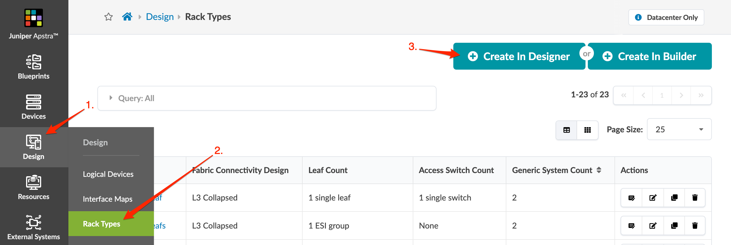
Apstra ships with many predefined rack types. Before creating your own, verify that it doesn't already exist in the global catalog (Design > Rack Types). When you create a rack type, first verify that the logical devices you need are in the global catalog (Design > Logical Devices).

  1. From the left navigation menu, navigate to Design > Rack Type and click Create in Designer.
    Juniper Apstra interface showing the Rack Types section under Design menu with navigation steps highlighted by red arrows.
  2. In the Create Rack Type dialog, enter a unique rack type name that is 17 characters or fewer (RackType1 in this example).
  3. Select L3 Clos fabric connectivity design for this example.
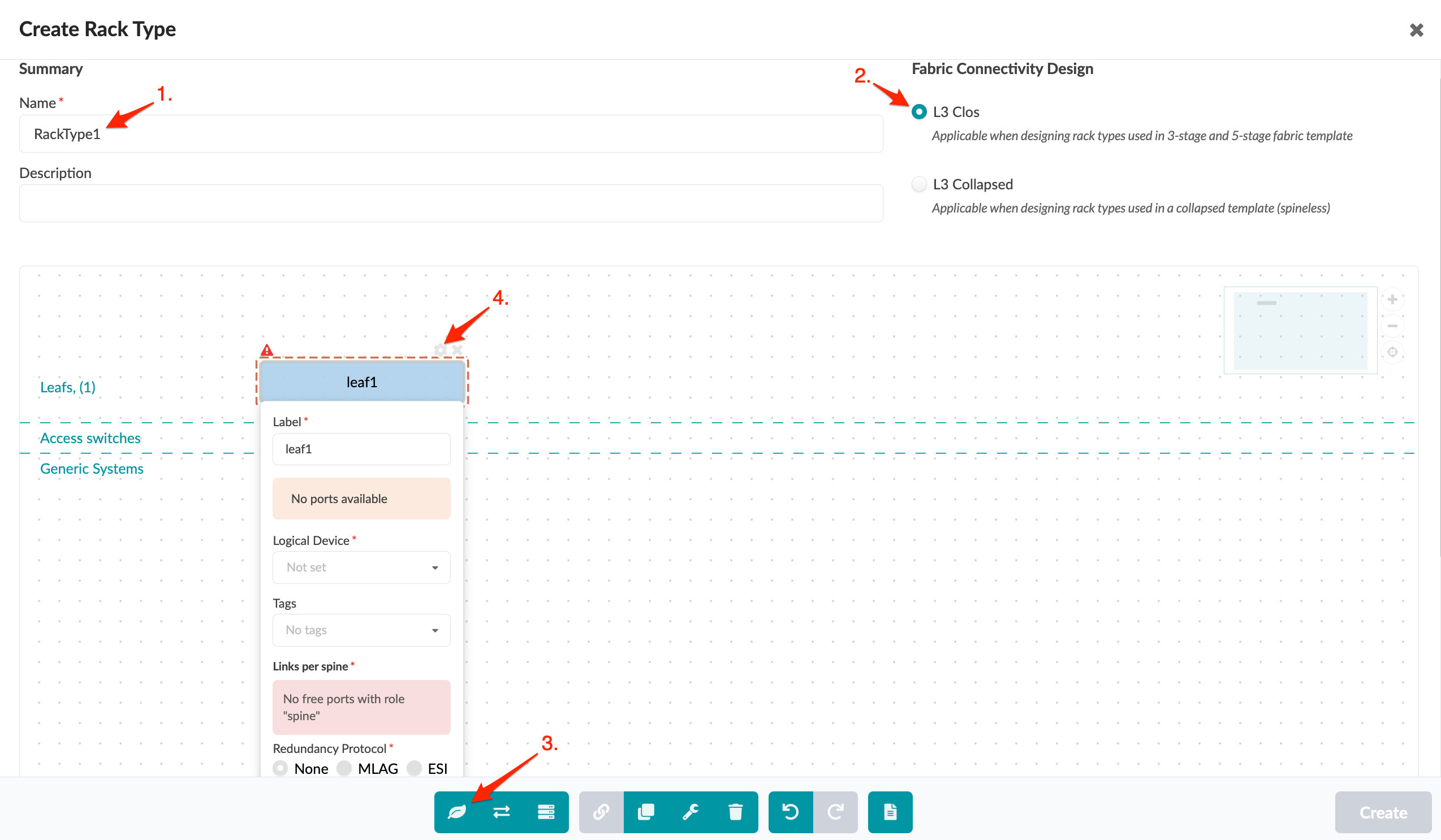
  4. Click the Add Leaf button (first selection in bottom row), then in the upper-right of the leaf element that appears click the gear to open its parameters.
    Creating a rack type in network design tool with name RackType1, L3 Clos selected, toolbar icons, and leaf1 configuration.
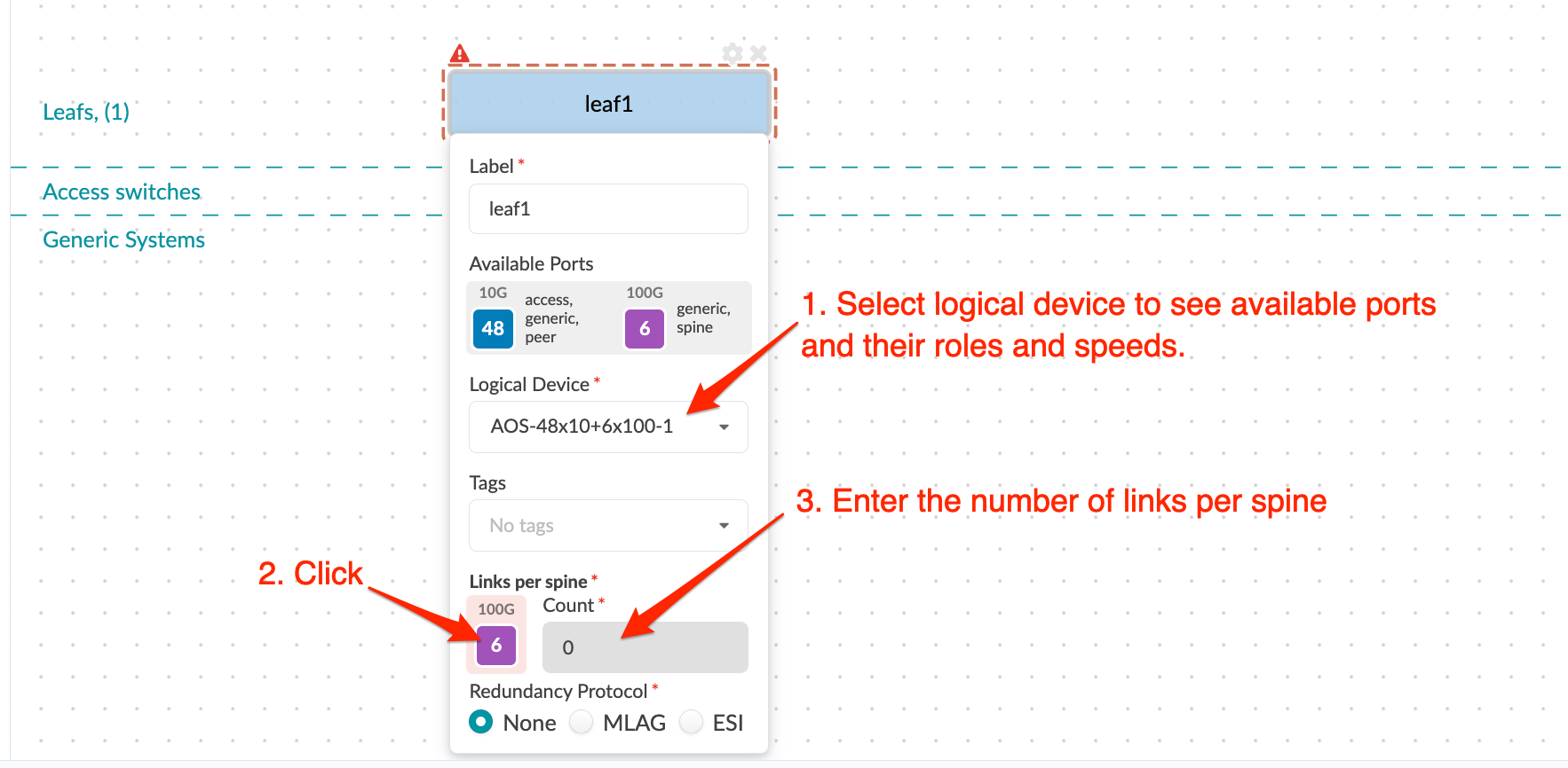
  5. Change the default label (leaf name) if you like, then select a logical device from the drop-down list. The available selections include all logical devices in the design (global) catalog that have a spine role. We're selecting AOS-48x10+6x100-1 for our example.
    Network configuration interface for leaf device leaf1 showing 48 10G and 6 100G ports available. Options for logical device type, links per spine, and redundancy protocol are displayed.
  6. Enter the number of links per spine (2 in our example), then click outside the leaf dialog to close it.
  7. Click the Add Leaf button again and enter a name for the second leaf, or leave the default name. (We've left the default as leaf2.) Enter the same information as for the first leaf, then click outside the leaf dialog to close it.
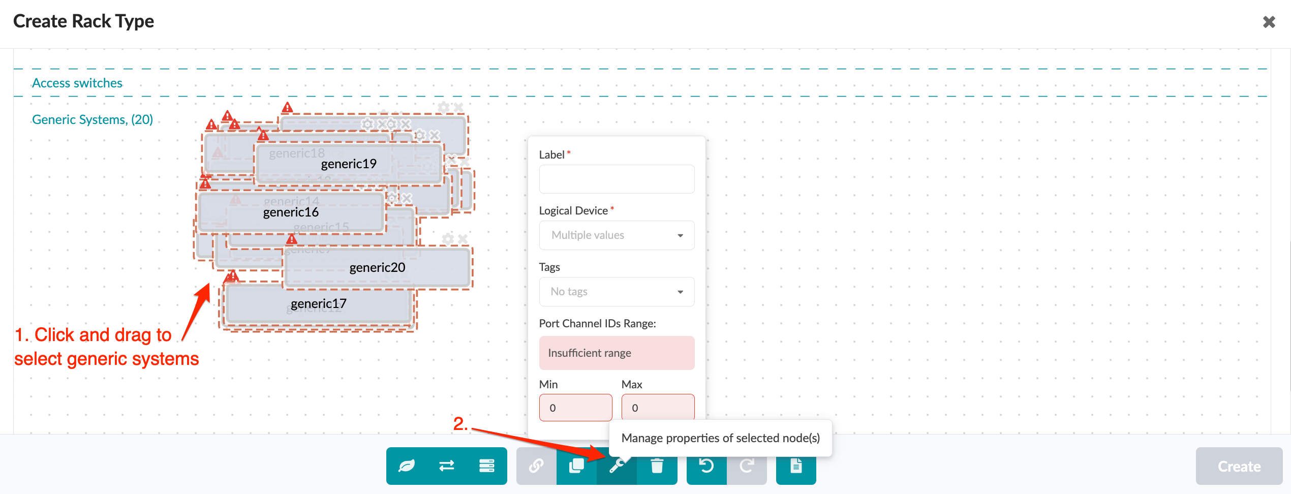
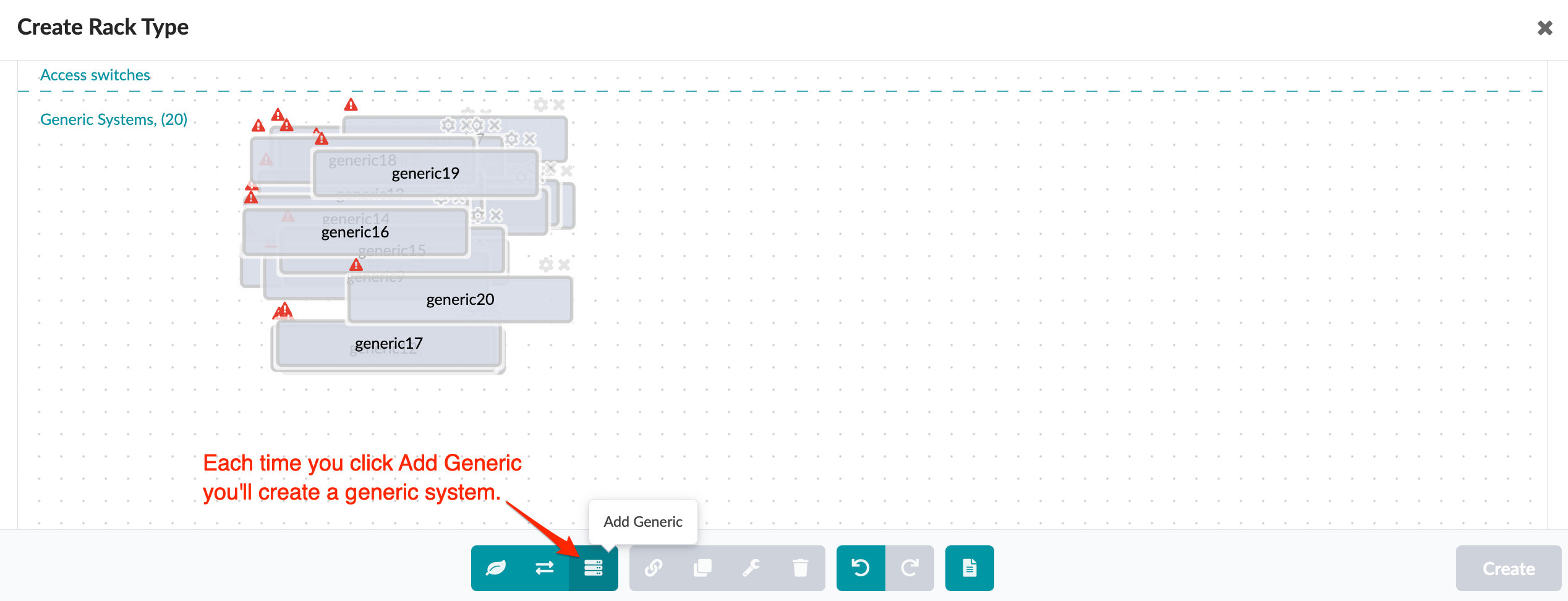
  8. Now for the generic systems. You can create many generic systems at once, then assign a logical device to them all at once. Click the Add Generic button (third selection in bottom row) 20 times, because we want 20 generic systems for our first leaf.
    User interface for creating rack types with overlapping Generic Systems labeled generic14, generic15, and generic16. Warning icons indicate issues. Access Switches section at the top. Add Generic button creates new systems. Toolbar includes undo, redo, and delete functions.
  9. Click and drag across all generic systems, then click the Manage properties of selected node(s) button in the bottom row.
  10. Select a logical device from the drop-down list. The available selections include all logical devices in the design (global) catalog that have a generic role. We're selecting AOS-2x10⁻¹ for our example.