Step 1: Begin
In this guide, we provide a simple, three-step path, to quickly get you up and running with the Juniper Support Insight (JSI) solution. We’ve simplified and shortened the installation and configuration steps.
Meet Juniper Support Insights
Juniper® Support Insights (JSI) is a cloud-based support solution that gives IT and network operations teams operational insights into their networks. JSI aims to transform the customer support experience by providing Juniper and its customers with insights that help improve the network performance and uptime. JSI collects data from Junos OS-based devices on customer networks, correlates it with Juniper-specific knowledge (such as service contract status, and End of Life and End of Support states), and then curates that into actionable insights.
Virtual Lightweight Collector
The Virtual Lightweight Collector (vLWC) is a VMware-ready data collection tool that gathers operational data from Juniper devices on customer networks. JSI uses this data to provide IT and network operations teams with actionable operational insights into the onboarded Juniper devices on customer networks. The vLWC uses your existing VMWare infrastructure to provide a virtualized solution while offering the capabilities of the LWC.
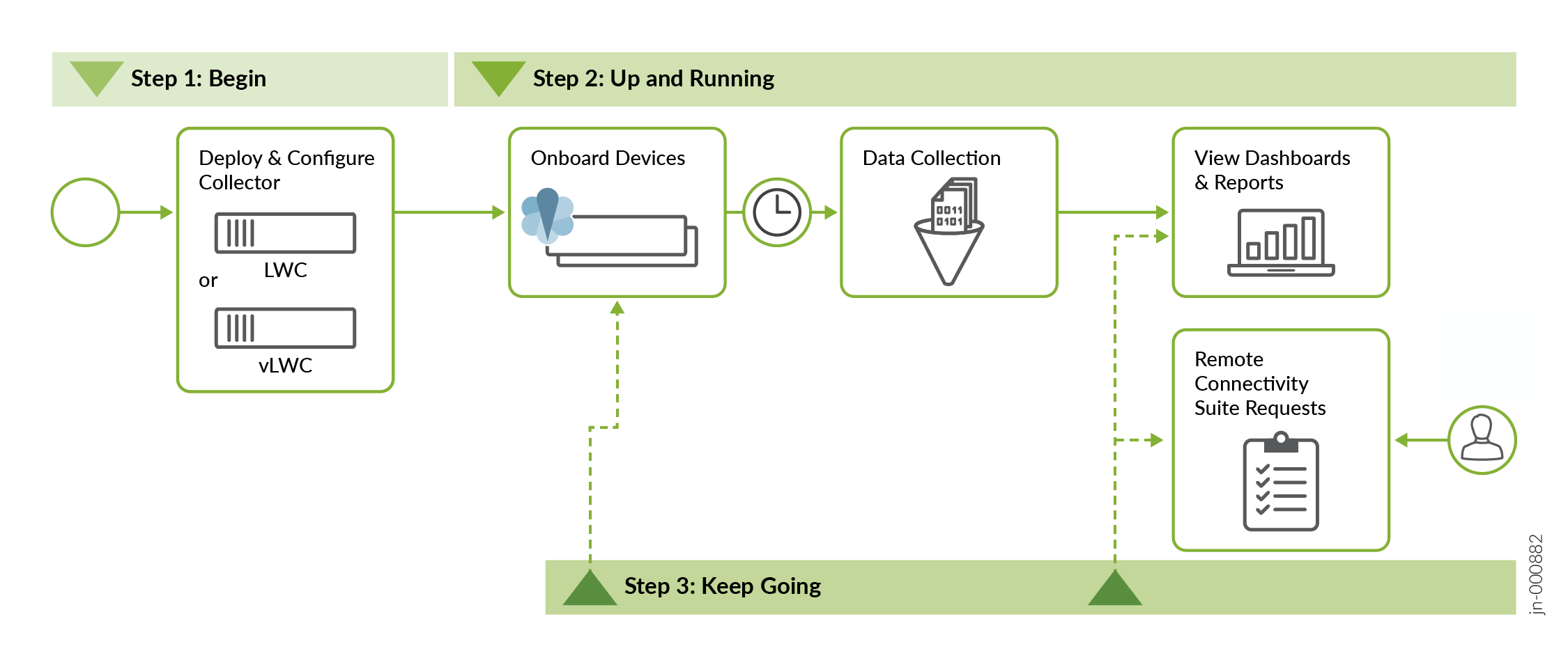
At a high level, getting started with the JSI solution involves the following steps:
-
Installing and configuring a Virtual Lightweight Collector (vLWC)
-
Onboarding a set of Junos devices to JSI to initiate data collection
-
Viewing notifications about device onboarding and data collection
-
Viewing operational dashboards and reports
This Quick Start guide assumes that you have ordered the JSI-vLWC solution, which is available as part of Juniper Care support service, and that you have an active contract. If you have not ordered the solution, please contact your Juniper Account or Services teams. Accessing and using JSI is subject to the Juniper Purchase and License Agreement (JPLA). For general information on JSI, see Juniper Support Insights Datasheet.
Install and Configure the Virtual Lightweight Collector
In this guide, we show you how to install and configure the vLWC on a VMWare environment.
Before You BeginTo successfully install and deploy vLWC, you must meet the following requirements:
-
VMware vCenter Server access (using VMware vSphere Client, version 6.7.0 or later)
-
One of the following minimum hardware requirements:
Table 1: Hardware Requirements Configuration Type Total Devices Supported
Number of vCPUs Memory Storage Small
Up to 10,000 devices
6 CPUs
16 GB RAM
400 GB disk space
Large
Up to 20,000 devices
12 CPUs
32 GB RAM
400 GB disk space
Warning:The vLWC can experience data collection issues if your system does not meet the minimum requirements. A lack of CPU and/or memory resources can cause the vLWC to go into a holding pattern and stop collecting data.
-
Three VM network interfaces:
Table 2: Interface Description Connectivity Interface Name Description Internal
int
Internal network to access the Junos devices being monitored by JSI. This network should not have access to the Internet.
External
ext
External network with HTTP/HTTPS and DNS Internet connectivity to connect to Juniper Cloud directly or through an active proxy server.
Management
cap
Connectivity to the management network host services:
-
Port 443/HTTPS for the Captive Portal web page
-
Port 22/SSH for the JSI shell
Note:While configuring the internal, external, and management interfaces, you must ensure that the subnet of the IP address assigned to the internal network port, external network port, and captive (management) portal are different from each other.
-
-
The vLWC software is provided as a single downloadable OVA file.
Note:There are two end-user scenarios:
-
Customer—A customer can request the vLWC software for themselves.
-
Partner—A partner can request the vLWC software and then either associate it to themselves or to one of their customer accounts.
To download the vLWC software, visit the vLWC request page on Juniper Support Portal at https://supportportal.juniper.net/s/vlwc-form, submit a form with the requested information, and receive a link over an email to download the vLWC software. Refer Download vLWC Software for more information.
Note:-
The OVA file will be created specifically for your installation. It contains your serial number as an encrypted vApp property that will be used during the initial boot process of the VM.
-
You can deploy only one vLWC OVA image with a unique serial number in your network. Deploying multiple vLWC OVA images with the same serial number is not supported. If you want to deploy multiple instances of vLWC in your network (for example, vLWC for production and lab), you must request a separate vLWC OVA image by submitting another request form.
-
-
Support for VMXNET3 network adapters.
Here's how to install vLWC using the vCenter Server:
-
Depending on where your OVA file is available, select the
URL option and provide the URL to the OVA file,
or select the Local file option and click
Choose Files to browse the local drive and upload
the vLWC OVA image. Click Next.
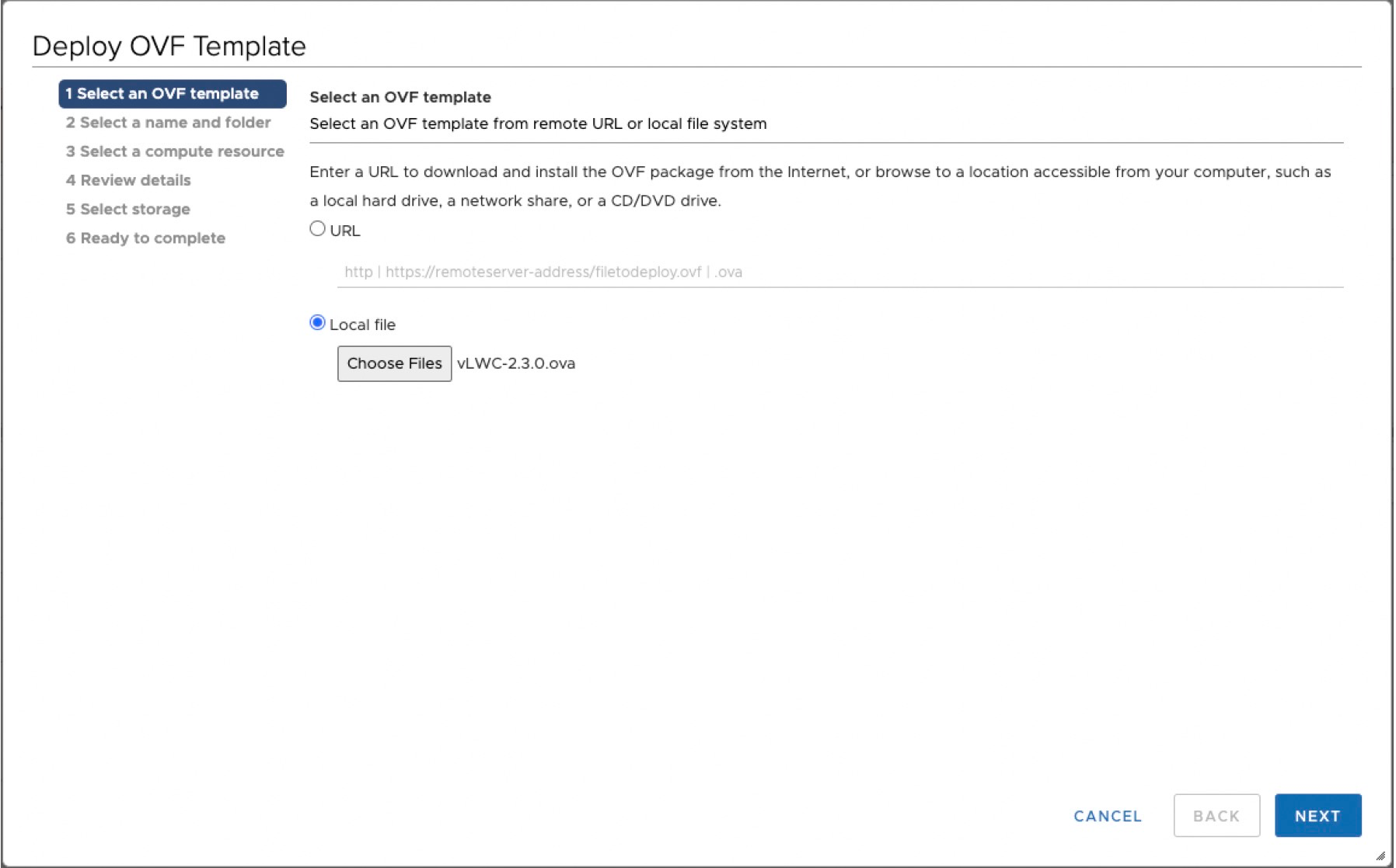
The Select a name and folder page opens.
-
Select the VMWare network to attach to each network interface using the
Destination Network drop-down for each of the source network. You can ignore
the IP allocation settings as they are not used by the vLWC. Click
Next.
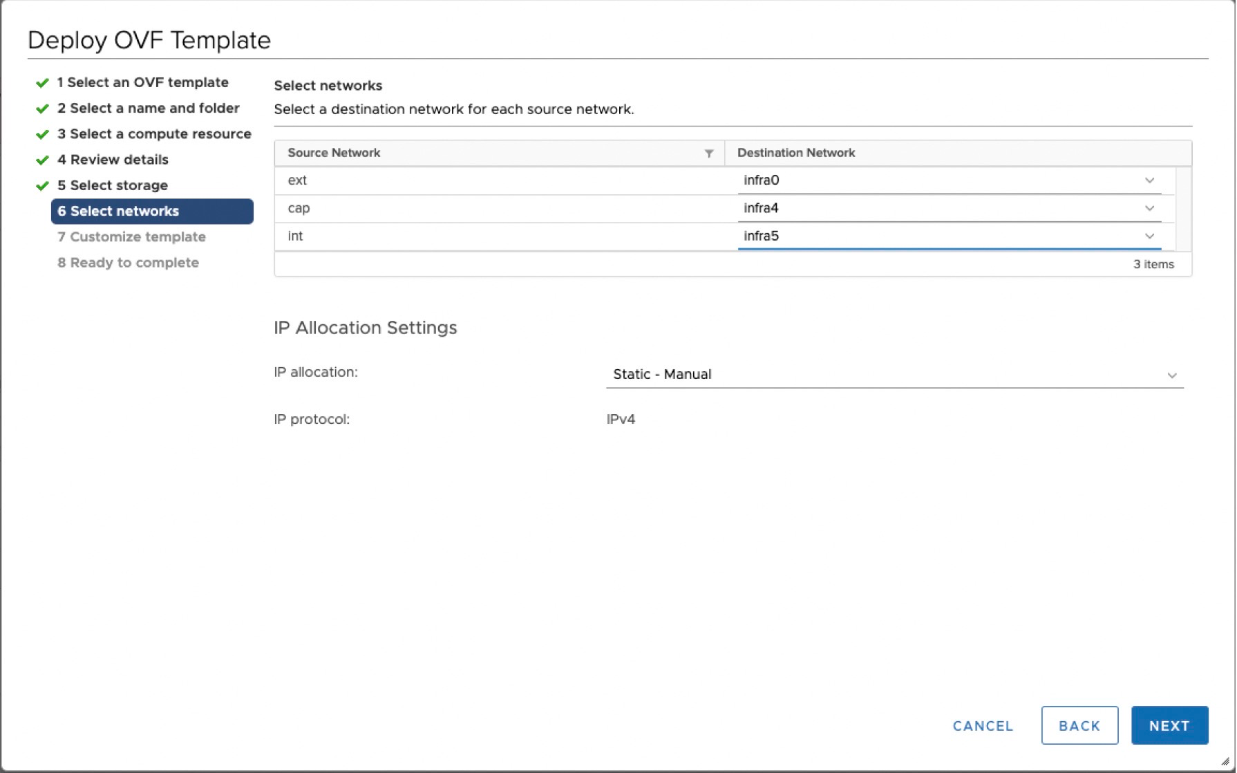
The Customize template page opens.
-
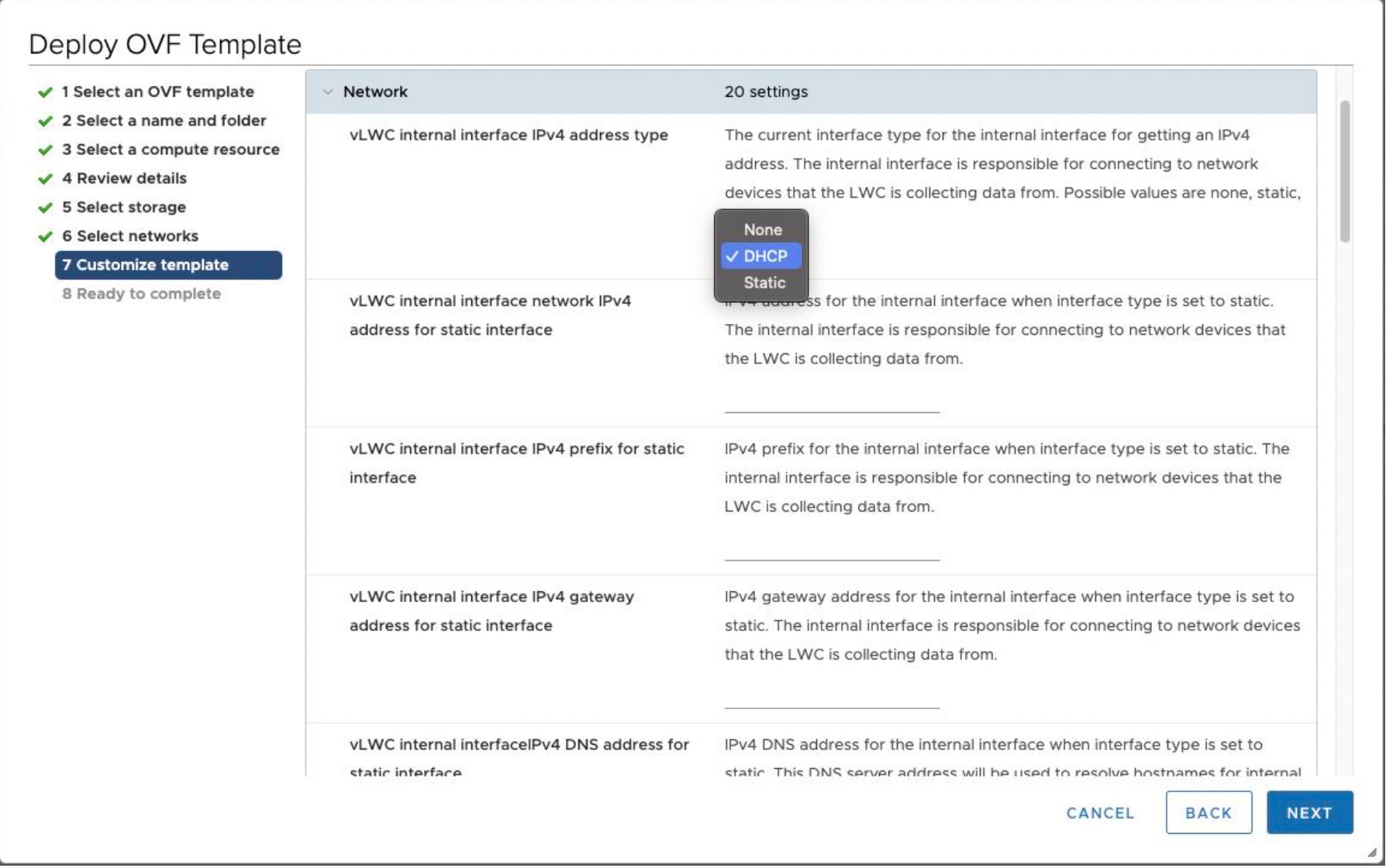
Specify the network settings for each vLWC interface over a series of 20 vApp
properties. For each interface, select the correct address type. For static
address, specify the necessary settings for that
interface.
The internal and external interfaces must each have unique a DNS entry.
Table 3: Supported IP Address Versions for Interfaces Interface Supported IP Address Internal
IPv4 or IPv6 address
External
IPv4 address only
Management
IPv4 address only
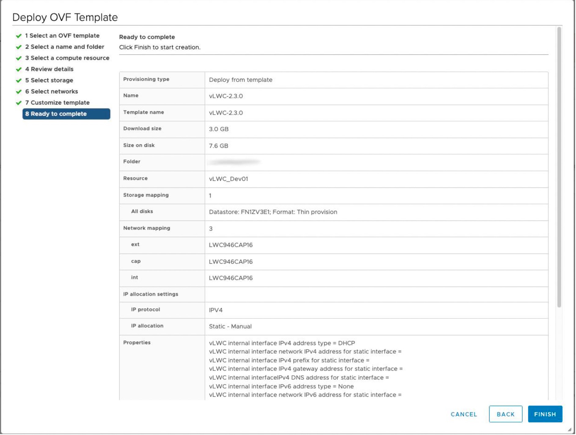
Once you have configured your network, click Next. The Ready to complete page opens.
-
Verify the configured settings for the vApp deployment and click
Finish to start the deployment of the vLWC.
-
To start vLWC, you can right-click the newly created vApp and click
Power On from the Actions menu.
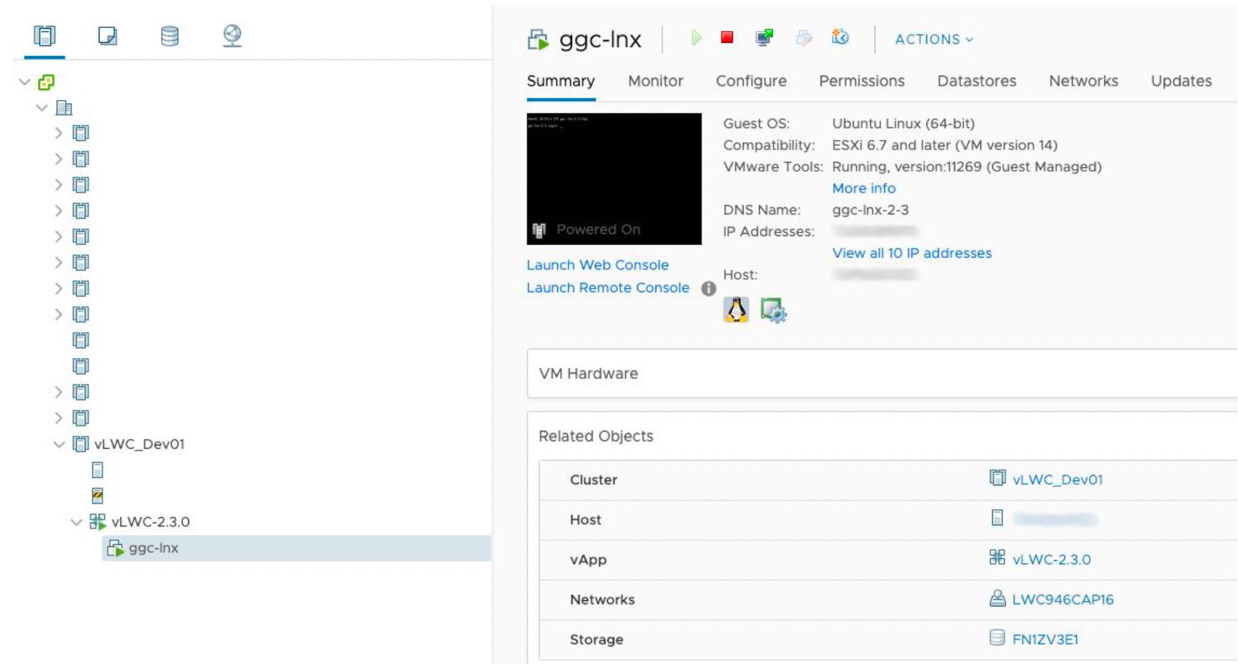
The vLWC is now installed and running in your environment. To confirm, you can view the summary page of the ggc-lnx VM located under the vLWC vApp entry. It should show an Ubuntu Linux (64-bit) VM running with VMware Tools also running along with the IP addresses assigned to the VM in the IP addresses list.
Configure the Virtual Lightweight Collector
Once the vLWC vApp is installed, you can add or modify various vLWC settings through the Captive Portal web page (see Configure Network Settings through Captive Portal) or the JSI Shell (see Configure Network Settings Through JSI Shell).
You must connect to the captive portal from a local IP address. Connection to the captive portal from the browser will fail if the connection request originates from a non-local network.
Before you configure the Lightweight Collector (LWC), refer to the Internal and External Network Requirements.
Internal and External Network Requirements
vLWC requires:
-
An internal network port that connects the vLWC to the Juniper devices on the network.
-
An external network port that connects the vLWC to the Juniper Virtual Private Cloud.
Before connecting the vLWC to the internal network, ensure that you have:
-
A DHCP or static IP address.
-
IP connectivity to the Domain Name Server (DNS), all the direct devices on the network, and bastion hosts used (if applicable) to access the devices.
Note:Bastion hosts utilize a SOCKS5 proxy server to reach target devices in the customer's network. Bastion hosts also support connection hopping, where an SSH session is first established with a customer's Linux-based device, which then initiates a subsequent SSH session to the target device.
-
Enabled NETCONF in the Junos OS configuration of all target Juniper devices. The vLWC uses SSH credentials to connect to the devices on the network and, if used, bastion hosts.
Before connecting the vLWC to the external network, ensure that you have:
-
A DHCP or static IP address.
-
A DNS server in case you have selected a static address. In case of any subsequent change to the DNS, you must inform Juniper about it and get it updated. Otherwise, the vLWC might lose connectivity to the external endpoints.
The vLWC supports real static, private static, or DHCP addresses. It prefers Network Address Translation (NAT).
-
Accessibility to the DNS and IP addresses specified in Table 4 through the IP addresses assigned to external port on the vLWC.
Table 4: Outbound Connectivity Requirements Description DNS Name IP Address Port Juniper cloud AWSProxy-prod.jssprod.junipercloud.net 52.223.32.79, 35.71.174.221, 35.164.173.102, 52.26.8.178, 54.149.201.209 443 Note:-
The IP addresses assigned to the internal and external interfaces must be from different subnets.
-
The internal and external interfaces must each have a unique DNS entry.
Ensure that these interfaces can reach their respective DNS servers over both UDP and TCP on port 53.
-
Configure Network Settings through Captive Portal
Here's how to view network status and configure network settings using the vLWC Captive Portal webpage:
-
Enter the vLWC serial number in the Serial
Number field and click Submit to
log in.
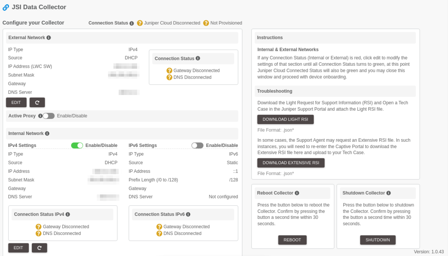
On successful login, the JSI Data Collector page appears.
The following image displays the JSI Data Collector page when the vLWC is not connected.
 Note:
Note:If the default DHCP configuration on the vLWC is successful, the Captive Portal web page shows the vLWC's connection status as connected, and populates the fields in all the configurations sections appropriately.
Click the Refresh icon under the External Network or Internal Network sections to refresh the current connection states for that section.
The JSI Data Collector page displays configuration sections for the following:
-
External Network—Lets you configure external network port that connects the vLWC to the Juniper's Cloud. Supports DHCP and static addressing. The External Network configuration is used to perform device provisioning.
-
Internal Networks—Lets you configure the internal network port that connects the vLWC to the Juniper devices on your network. Supports DHCP and static addressing.
-
Active Proxy—Lets you configure the active proxy IP address as well as the port number if your network infrastructure controls access to the Internet though an active proxy. You need not configure this element if you are not using an active proxy.
-
-
After modifying the fields, click Update to
apply the changes and return to the homepage (the JSI Data Collector
page).
If you want to discard your changes, click Cancel.
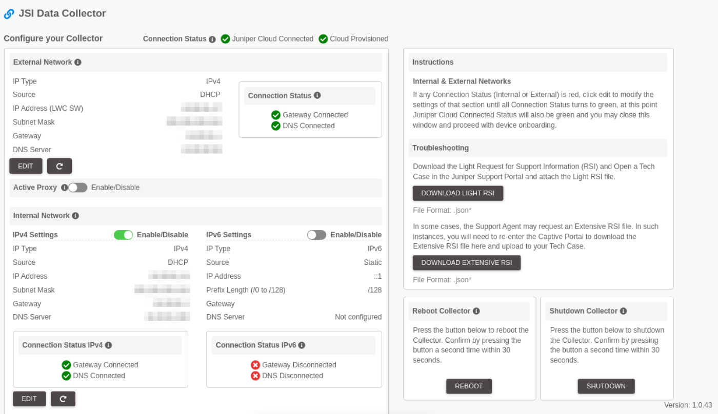
If the vLWC connects to the gateway and DNS successfully, the respective configuration element (internal or external network section) on the JSI Data Collector homepage shows the connection status as Gateway Connected and DNS Connected with green tick marks against them.
The JSI Data Collector homepage displays the Connection Status as:
-
Juniper Cloud Connected if the external connectivity to the Juniper Cloud is established and the active proxy (if applicable) settings are correctly configured.
-
Cloud Provisioned if the device is connected to Juniper Cloud and has completed the Zero Touch Experience (ZTE) process. After the Cloud connection status becomes Juniper Cloud Connected, it takes about 10 minutes for the provision status to become Cloud Provisioned.
The following image displays the JSI Data Collector page when the vLWC is connected successfully.
If the vLWC does not connect to the cloud, click Download Light RSI to download the light RSI file, create a Tech Case in the Juniper Support Portal, and attach the downloaded RSI file to the case.
In some cases, the Juniper support engineer might ask you to attach the Extensive RSI file to the case. To download it, click the Download Extensive RSI.
-