Step 3: Keep Going
The overlay networks you just created all share the same physical infrastructure, but are completely separate from each other. Users in one overlay network won’t be able to communicate with users in another overlay network.
We’ll show you how to open a path between networks through a physical network function (PNF), in this case, an SRX Series firewall. You do this by creating a PNF service chain that runs from one logical router to another through the firewall.
Onboard the PNF Device
To create a PNF service chain, you first have to onboard the PNF device. You do this by using the same Create Fabric wizard you used when you onboarded the fabric underlay, but this time you’re discovering an existing (brownfield, already configured) device. By onboarding this device, you’re telling Contrail Networking to add this device to the fabric.
Contrail Networking then assigns IP addresses to the fabric ports on the SRX Series device and on the attached switches from the PNF service chain subnet you specified earlier when you onboarded the fabric (Step 4 in Onboard a New Fabric (Greenfield)). Contrail Networking also configures the routing protocols to allow the SRX Series device to exchange routes with the fabric.
Here’s the PNF device you’ll be onboarding and the PNF service chain you’ll be setting up:
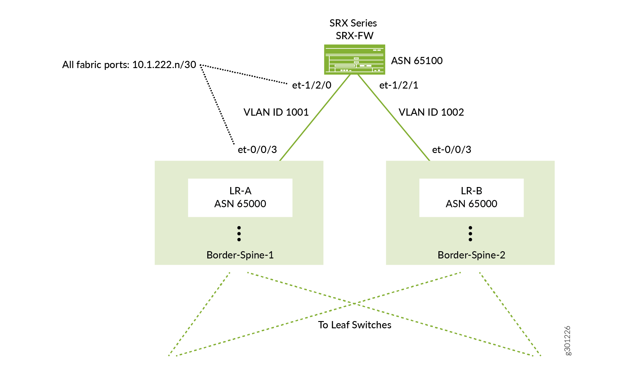
Before you begin, physically connect the SRX Series firewall to both spine switches (in a centrally routed and bridged model). Make sure the SRX Series device is already up and running and contains basic configuration such as a username and password, hostname, management and loopback IP addresses, but no IP addresses on the interfaces that you’ll use to connect to the fabric nor any policies that govern traffic to and from the fabric.
- Select INFRASTRUCTURE>Fabrics and click the
fabric underlay that you onboarded previously.
The Fabric devices window appears listing all the devices in the fabric.
- Select Action>Brownfield wizard.
The Create Fabric wizard is launched, but you’re not creating a fabric in this procedure. You’re using the wizard to add a PNF device to the fabric you onboarded earlier.
- Fill in the PNF configuration. Here are mandatory fields
along with example values. Because this is an existing SRX Series
device, you supply the existing login credentials and the existing
management IP address. You can leave all other settings at their default
values.
Fields
Meaning
Example
Device credentials>Username
The username to log in to the device.
<existing-username>
Device credentials>Password
The password to log in to the device.
<existing-password>
Management subnets>CIDR
The IP address of the device on the management network.
<existing-management-IP-address>
This is a /32 address.
- Click Next to launch the device discovery process.
- When you see the message Job execution completed successfully in the log section, click Next to progress to role assignment.
- Select the row for the PNF device you just discovered
and click the Assign Role icon on the far right of the
row.
The Assign role to devices window appears.
- Set the role for the SRX Series device and click Assign.
Role
Setting
Physical
pnf
Routing Bridging Roles
PNF-Servicechain
Note: You had set this same role on the spine switches earlier.
- Click Autoconfigure to push the new configuration onto the devices based on their assigned roles.
- When the progress panel displays Job summary: Job execution completed successfully, click Next and then click Finish to skip the assignment of telemetry profiles.
Create the PNF Service Chain
With the PNF device now part of the fabric, you can logically insert it between two overlay networks. You insert the PNF device by setting up a PNF service chain.
To create the service chain, you first create a template that describes how the PNF device is connected to the fabric. The PNF device can be reused for multiple overlay applications. Creating a template saves you from configuring this information for future service chains.
- Create the service chain template.
- Select SERVICES>Catalog to bring up the Catalog page.
- Click the PNF tab to bring up the PNF Service
Templates window and click Create>Template.
The Create PNF Service Template page appears.
- Fill in the fields on this page according to your desired
setup. Here are the mandatory fields along with values that match
our example PNF configuration.
Field
Meaning
Example
Name
The name you want to call this service template.
my-service-chain
PNF Device
The name of the device. This is the existing hostname of the SRX Series device.
SRX-FW
PNF Left Interface
The interface on one side of the SRX Series device.
et-1/2/0
PNF Left Fabric
The name of the fabric on one side of the SRX Series device.
my-fabric
PNF Left Attachment Points>Physical Router
The router attached to the left interface of the SRX Series device.
Border-Spine-1
PNF Left Attachment Points>Left Interface
The interface on the router attached to the left interface of the SRX Series device.
et-0/0/3
PNF Right Interface
The interface on the other side of the SRX Series device.
et-1/2/1
PNF Right Fabric
The name of the fabric on the other side of the SRX Series device.
my-fabric
PNF Right Attachment Points>Physical Router
The router attached to the right interface of the SRX Series device.
Border-Spine-2
PNF Right Attachment Points>Right Interface
The interface on the router attached to the right interface of the SRX Series device.
et-0/0/3
- Click Create to create the template. The name of the template is the name you specified appended by the template designation (for example, my-service-chain-template).
- Create the service chain using this template.
- Select SERVICES>Deployments to bring up the Deployments page.
- Click the PNF tab to bring up the PNF Service
Instances window and click Create>Instance.
The Create PNF Service Instance page appears.
- Fill in the fields on this page according to your desired
setup. Here are the mandatory fields along with values that match
our example PNF configuration.
Fields
Meaning
Example
Name
The name you want to call this service chain instance.
my-service-chain
Service Template
The service template you want to use. This is the name of the service template you created earlier.
my-service-chain-template
PNF eBGP ASN
The ASN for the PNF device. This is used by eBGP to exchange routes in the overlay.
65100
Left Tenant Logical Router
The logical router attached to the left interface.
Deciding which is the left logical router and which is the right logical router is arbitrary because each spine switch has the same two logical routers instantiated.
LR-A
PNF Left BGP Peer ASN
The ASN for the left overlay network. There is one ASN for the entire overlay.
65000
Left Service VLAN
The VLAN ID for the left interface.
1001
Right Tenant Logical Router
The logical router attached to the right interface. This is the other logical router.
LR-B
PNF Right BGP Peer ASN
The ASN for the right overlay network. There is one ASN for the entire overlay.
65000
Right Service VLAN
The VLAN ID for the right interface.
1002
- Click Create to push the configuration to the devices.
You have now created the service chain. The SRX Series device uses eBGP to learn routes from one logical router and advertises the routes to the other logical router. Once the routes are known, internetwork traffic begins to traverse the SRX Series device.
By default, Contrail Networking configures the SRX Series device to be permissive (that is, an <any>-<any>-<any> permit policy). To change the policy, log in to the SRX Series device and configure the policy as you normally do.
What’s Next?
Now that you've set up Contrail Networking with a basic configuration, here are some things you can do next.
If you want to | Then |
|---|---|
See a Contrail Networking use case with a deeper explanation of the steps you’ve just learned | |
See a cheatsheet of the steps you’ve just learned | See Contrail Enterprise Multicloud Getting Started Guide - Fabric Management |
Configure advanced fabric management features | See the Contrail Networking Fabric Lifecycle Management Guide |
General Information
If you want to | Then |
|---|---|
See all documentation available for Contrail Networking | |
See all documentation available for Contrail Insights | |
See a solutions guide for fabric management | See Data Center: Contrail Enterprise Multicloud for Fabric Management |
Stay up-to-date with new and changed features and known and resolved issues |
Learn With Videos
Our video library continues to grow! We’ve created many, many videos that demonstrate how to do everything from install your hardware to configure advanced Junos OS network features. Here are some great video and training resources that will help you expand your knowledge of Junos OS.
If you want to | Then |
|---|---|
View a video that shows you how to install the Contrail Command GUI and use it to deploy Contrail Networking 2005 and Contrail Insights in your network. | Watch Contrail Networking 2005 and Contrail Insights Installation |
Get short and concise tips and instructions that provide quick answers, clarity, and insight into specific features and functions of Juniper technologies | See Learning with Juniper on the Juniper Networks main YouTube page |
View a list of the many free technical trainings we offer at Juniper | Visit the Getting Started page on the Juniper Learning Portal |