SSR1400 Site Guidelines and Requirements
General Site Installation Guidelines
The following precautions help you plan an acceptable operating environment for your SSR1400 appliance and avoid environmentally caused equipment failures:
- Keep the area around the chassis free from dust.
- Follow prescribed airflow guidelines to ensure that the cooling system functions properly and that exhaust from other equipment does not blow into the intake vents of the appliance.
- Follow the ESD procedures to avoid damaging equipment. Static discharge can cause components to fail completely or intermittently over time.
- Install the appliance in a secure area, so that only authorized personnel can access the appliance.
Site Electrical Wiring Guidelines
Table 1 describes the factors you must consider while planning the electrical wiring at your site.
You must provide a properly grounded and shielded environment and use electrical surge-suppression devices.
Avertissement Vous devez établir un environnement protégé et convenablement mis à la terre et utiliser des dispositifs de parasurtension.
| Site Wiring Factor | Guidelines |
|---|---|
| Signaling limitations |
If your site experiences any of the following problems, consult experts in electrical surge suppression and shielding:
|
| Radio frequency interference |
To reduce or eliminate RFI from your site wiring, do the following:
|
| Electromagnetic compatibility |
If your site is susceptible to problems with electromagnetic compatibility (EMC), particularly from lightning or radio transmitters, seek expert advice. Some of the problems caused by strong sources of electromagnetic interference (EMI) are:
|
Environmental Requirements and Specifications for SSR1400
The SSR1400 must be housed in dry, clean, well-ventilated, and temperature-controlled environment. Follow these environmental guidelines:
-
The site must be dust-free because dust can clog air intake vent, reducing the efficiency of the cooling system.
-
Maintain ambient airflow for normal operation. If the airflow is blocked or restricted, or if the intake air is too warm, the appliance might overheat.
The following table lists the environmental specifications for the SSR1400.
| Description | Value |
|---|---|
| Operating temperature |
0° C to 40° C (32° F to 104° F) |
| Storage temperature | -20° C to 70° C (-4° F to 158° F) |
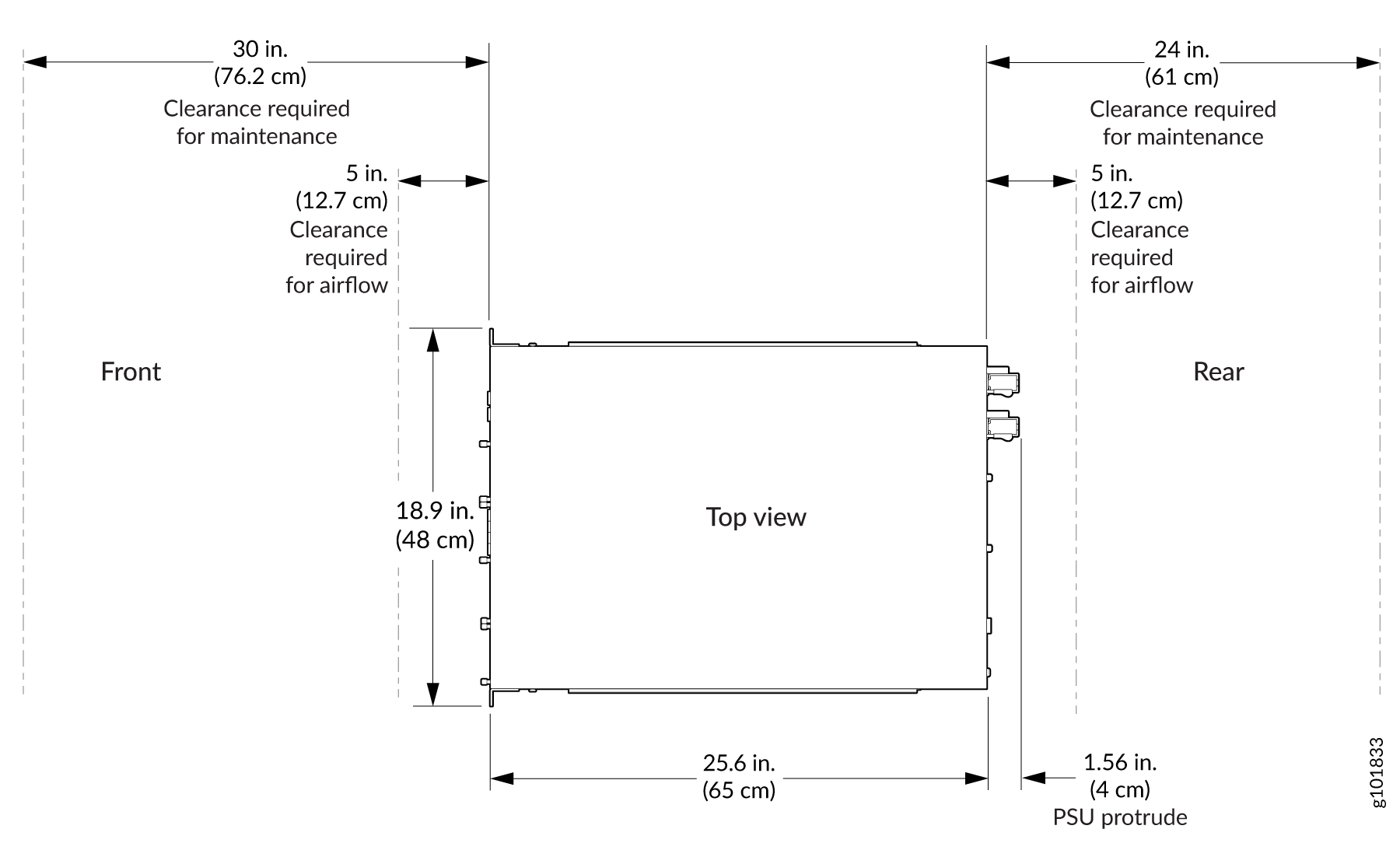
Clearance Requirements for Hardware Maintenance of SSR1400
When planning the site for installing an SSR1400, you must allow sufficient clearance around the installed chassis.
-
For the operating temperature of the SSR1400 to be optimal, the airflow around the chassis must be unrestricted. See Cooling System for more information about the airflow through the chassis.
-
For service personnel to remove and install hardware components, and to accommodate the interface and power cable bend radius, there must be adequate space at the front and rear of the appliance. Allow at least 24 in. (61 cm) of space both at the front and the rear of the appliance.
-
If you are mounting the appliance in a rack with other equipment, or if you are placing it on the desktop near other equipment, ensure that the exhaust from other equipment does not blow into the intake vents of the chassis.
Rack Requirements for SSR1400
You can mount the SSR1400 on four-post racks. The rack mounting kit is shipped with the device. You can order a spare rack mounting kit (part number: JNP-RMK-SSRHE) separately if required. Table 3 provides the rack requirements and specifications for SSR1400.
| Rack Requirement | Guidelines |
|---|---|
| Rack type |
Use a four-post rack with bracket holes or hole patterns that are spaced at 1-U increments (1.75 in. or 4.45 cm). Ensure that the rack meets the size and strength requirements to support the weight. A U is the standard rack unit defined in Cabinets, Racks, Panels, and Associated Equipment (document number EIA-310–D) published by the Electronics Industry Association. |
| Mounting bracket hole spacing | Ensure that the holes in the mounting brackets are spaced at 1 U (1.75 in. or 4.45 cm) so that the device can be mounted in any rack that provides holes that are spaced at that distance. |
| Rack size and strength |
|
| Rack connection to building structure |
|