SSR1400 Chassis
Front Panel of an SSR1400
Figure 1 shows the front panel of an SSR1400. The SSR1400 comes with a claim code (QR code) that you can use to onboard the SSR1400 to Juniper Mist.
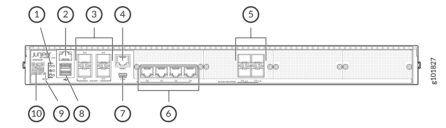
1 — Chassis LEDs | 6 — 1 GbE Ethernet ports (1/0 through 1/3) |
2 — RJ-45 Console port | 7 — Micro-USB Console port |
3 — 10 GbE SFP+ ports (0/0 through 0/3) | 8 — USB 3.0 ports |
4 — 1 GbE management port (for Mist operations) | 9 — RESET button |
5 — 1/10/25 GbE SFP28 ports (2/0 through 2/3) | 10 — Claim code |
Rear Panel of an SSR1400
Figure 2 shows the rear panel of an SSR1400.
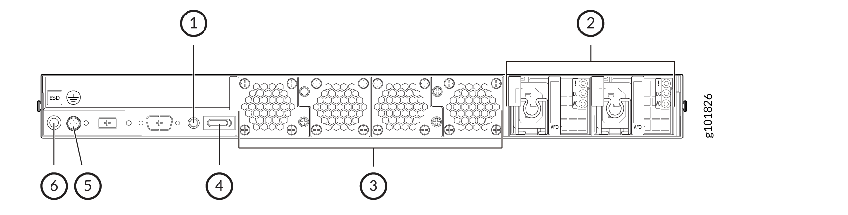
1 — Alarm switch | 4 — Power switch |
2 — AC or DC power supply units | 5 — Earth grounding |
3 — Fans | 6 — ESD point |
Power supply units are specific to the chassis; AC PSU's are only to be used with an SSR1400. DC PSU's are only to be used with an SSR1400-DC.
Chassis Physical Specifications for SSR1400
Table 1 summarizes the physical specifications of SSR1400.
| Model | Height | Width | Depth | Weight |
|---|---|---|---|---|
| SSR1400 | 44 mm | 438 mm | 650 mm | 19.2 kg (42.33 lbs.) |
Chassis Status LEDs
Figure 3 shows the LEDs on the front panel, and Table 2 describes the LEDs.
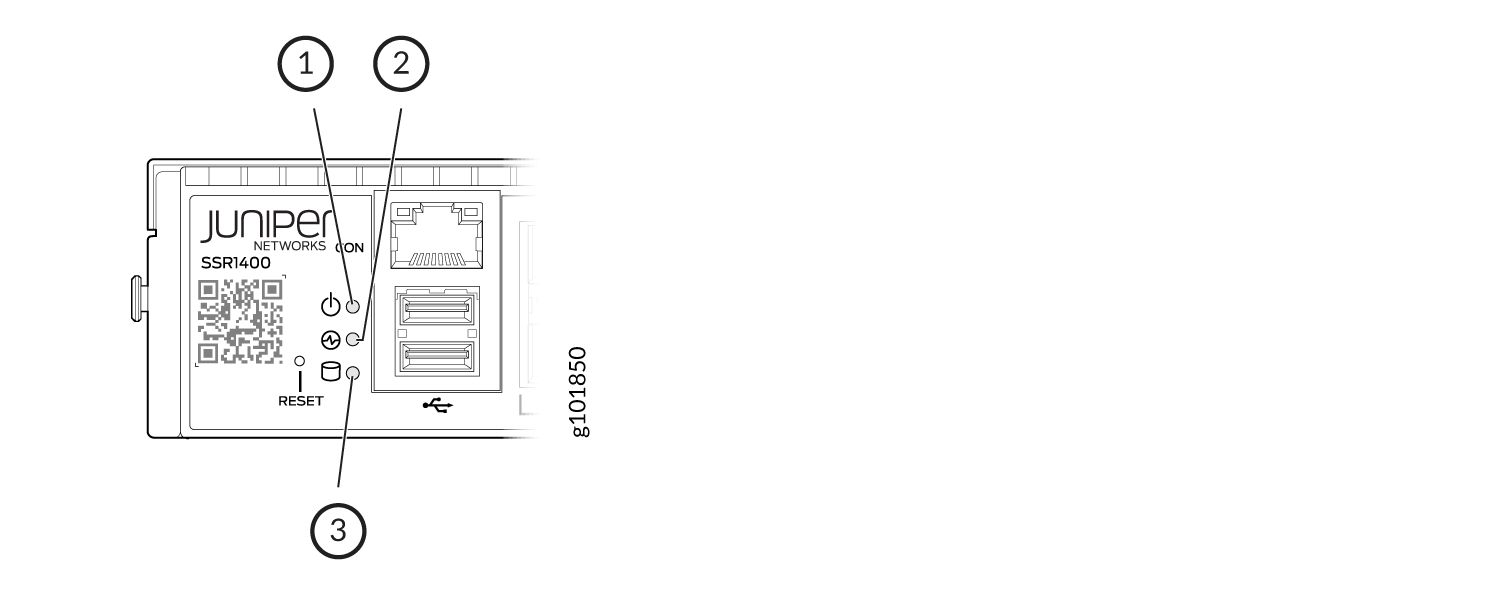
| Callout | LED | Description |
|---|---|---|
| 1 | Power |
|
| 2 | Status |
|
| 3 | SSD |
|
Network Port LEDs
Each network port uses two LEDs to indicate the link activity and speed. Figure 4 shows the location of the LEDs on the 10G SFP+ ports and Table 3 describes the LEDs.
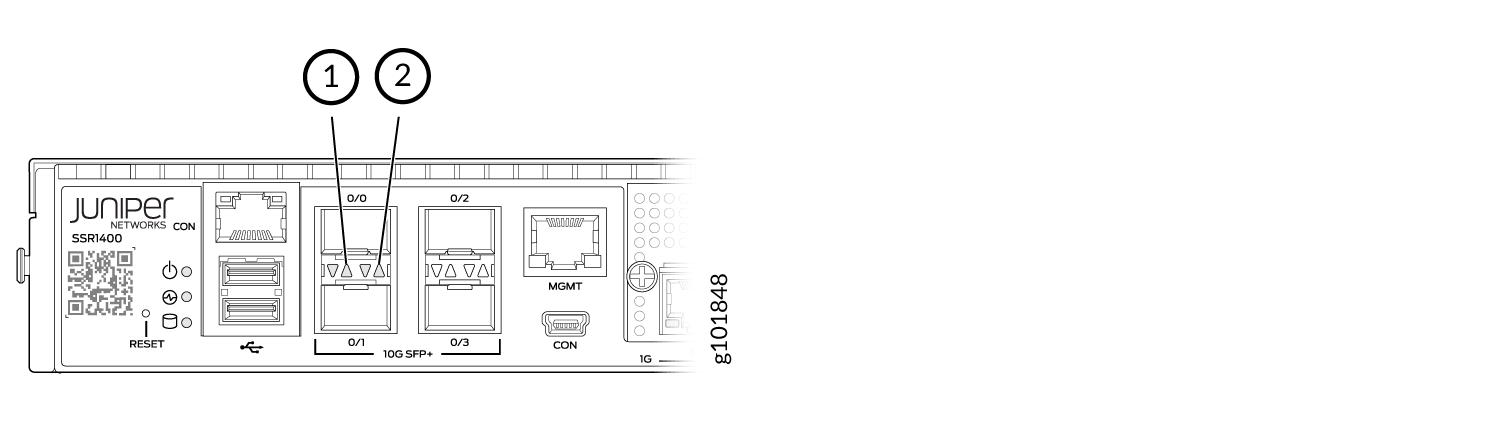
| Callout | LED | Description |
|---|---|---|
| 1 | Link Activity |
|
| 2 | Speed |
|
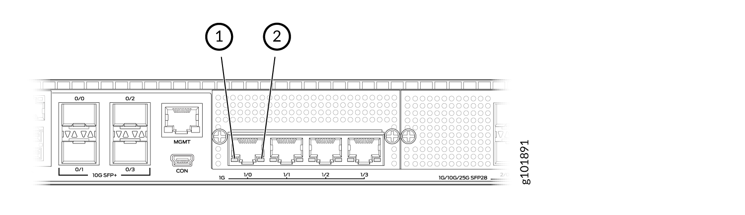
Figure 5 shows the location of the LEDs on the Ethernet ports and Table 4 describes the LEDs.
| Callout | LED | Description |
|---|---|---|
| 1 | Link Activity (LED on the left) |
|
| 2 | Speed (LED on the right) |
|
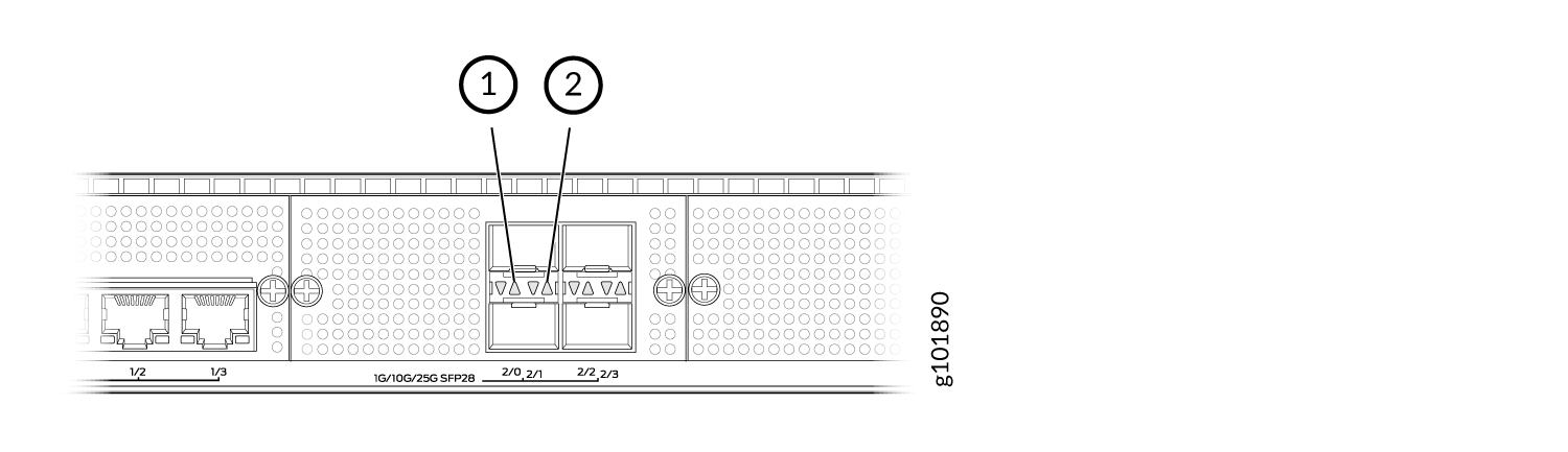
Figure 6 shows the location of the LEDs on the 1/10G SFP+ ports and Table 5 describes the LEDs.
| Callout | LED | Description |
|---|---|---|
| 1 | Link Activity (LED on the left) |
|
| 2 | Speed (LED on the right) |
|
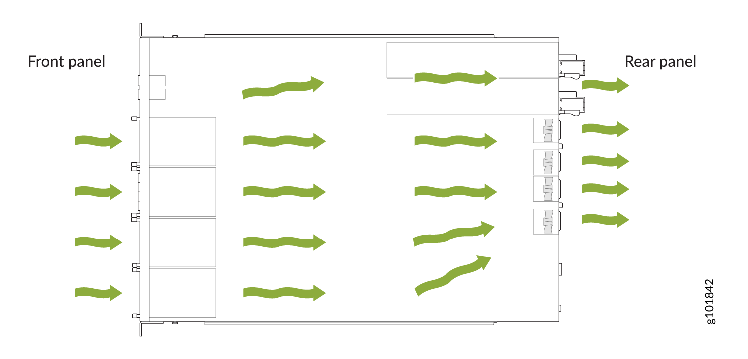
Cooling System
The cooling system of the SSR1400 consists of four fans, which are hot-insertable and hot-removable field-replaceable units (FRUs). You can remove and replace them without powering off the appliance or disrupting appliance functions.
The SSR1400 appliances have front-to-back airflow. The air is pulled in through the front of the chassis toward the fan modules, from where it is exhausted out of the chassis.
Power System
The SSR1400 appliance ships with two AC or two DC power supply units (1+1 redundancy) preinstalled. AC power supply units are hot-removable and hot-insertable field-replaceable units (FRU) when the second power supply is installed and running. You can remove and replace either of them without powering off the appliance or disrupting the appliance functions.
DC power supplies are not hot-swapable. DC power to the SSR1400-DC must be removed (circuit breaker shut off) and power cable disconnection must be performed by a licensed professional.
The power supplies are located at the rear of the chassis.
Matching AC or DC power supplies are used to provide redundancy and share power within a fully populated system. If one power supply fails or is removed, the remaining power supply redistributes the electrical load without interruption. The device reassesses the power required to support its configuration and issues errors if the available power is insufficient.
Each power supply is cooled by its own internal cooling system.
Only redundant AC power supplies support hot-swappable functionality.
If two power supply units are installed and only one power supply unit is connected to the power source, the device raises an alarm.
Do not mix AC and DC power supplies within the same device. Damage to the SSR1400 will occur. Power supply units are specific to the chassis; AC PSU's are only to be used with an SSR1400. DC PSU's are only to be used with an SSR1400-DC.
Each power supply has its own fan and is cooled by its own internal cooling system.
Table 6 lists the power specifications for the SSR1400 appliance.
The power supplies produce and distribute different output voltages to the SSR components according to their voltage requirements.
| Model | Input Voltage (Operating Range) | Input Line Frequency | Input Current Rating | Maximum Power Consumption | Power Supply Type |
|---|---|---|---|---|---|
| SSR1400 | 100–240 VAC | 50–60 Hz | 3–5 A | 650 W | External, hot swappable |
| SSR1300-DC (650W DC power supply) | -44 to -72 VDC | 6.2 A Maximum | 650 W @12 V | External |
AC Power Cord Specifications for the SSR1400
We ship detachable region-specific AC power cords with the chassis. The coupler is type C13 as described by International Electrotechnical Commission (IEC) standard 60320. The plug end of the power cord fits into the power source outlet that is standard for your geographical location.
Table 7 lists the AC power cords specifications provided for the power supplies for each country or region.
|
Country/Region |
Electrical Specifications |
Plug Standards |
Juniper Model Number |
Graphic |
|---|---|---|---|---|
|
Argentina |
250 VAC, 10 A, 50 Hz |
IRAM 2073 Type RA/3 |
CBL-EX-PWR-C13-AR |
No graphic available |
|
Australia |
250 VAC, 10 A, 50 Hz |
AS/NZS 3112 Type SAA/3 |
CBL-EX-PWR-C13-AU |
|
|
Brazil |
250 VAC, 10 A, 50 Hz |
NBR 14136 Type BR/3 |
CBL-EX-PWR-C13-BR |
No graphic available |
|
China |
250 VAC, 10 A, 50 Hz |
GB 1002-1996 Type PRC/3 |
CBL-EX-PWR-C13-CH |
|
|
Europe (except Italy, Switzerland, and United Kingdom) |
250 VAC, 10 A, 50 Hz |
CEE (7) VII Type VIIG |
CBL-EX-PWR-C13-EU |
|
|
India |
250 VAC, 10 A, 50 Hz |
IS 1293 Type IND/3 |
CBL-EX-PWR-C13-IN |
No graphic available |
|
Israel |
250 VAC, 10 A, 50 Hz |
SI 32/1971 Type IL/3G |
CBL-EX-PWR-C13-IL |
|
|
Italy |
250 VAC, 10 A, 50 Hz |
CEI 23-16 Type I/3G |
CBL-EX-PWR-C13-IT |
|
|
Japan |
125 VAC, 12 A, 50 Hz or 60 Hz |
JIS 8303 |
CBL-EX-PWR-C13-JP |
|
|
Korea |
250 VAC, 10 A, 50 Hz or 60 Hz |
CEE (7) VII Type VIIGK |
CBL-EX-PWR-C13-KR |
|
|
North America |
125 VAC, 13 A, 60 Hz |
NEMA 5-15 Type N5-15 |
CBL-EX-PWR-C13-US |
|
|
South Africa |
250 VAC, 10 A, 50 Hz |
SABS 164/1:1992 Type ZA/3 |
CBL-EX-PWR-C13-SA |
|
|
Switzerland |
250 VAC, 10 A, 50 Hz |
SEV 6534-2 Type 12G |
CBL-EX-PWR-C13-SZ |
No graphic available |
|
United Kingdom |
250 VAC, 10 A, 50 Hz |
BS 1363/A Type BS89/13 |
CBL-EX-PWR-C13-UK |
|
DC Power Cable Specifications for the SSR1400-DC
The DC power supply in slot 0 must be powered by dedicated power feeds derived from feed A, and the DC power supply in slot 1 must be powered by dedicated power feeds derived from feed B. This configuration provides the commonly deployed A/B feed redundancy for the system.
You must ensure that power connections maintain the proper polarity. The power source cables might be labeled (+) and (–) to indicate their polarity. There is no standard color coding for DC power cables. The color coding used by the external DC power source at your site determines the color coding for the leads on the power cables that attach to the terminal studs on each power supply.
For field-wiring connections, use copper conductors only.
Power cords and cables must not block access to the SSR components, or hang where people could trip on them.
The table below summarizes the specifications for the power cable(s), which you must supply.
|
Cable Type |
Quantity and Specification |
|---|---|
|
Power |
14-16 AWG, minimum 60° C wire, or as permitted by the local code |