Maintaining the SRX5600 Power System
Maintaining SRX5600 Firewall Power Supplies
Purpose
For optimum firewall performance, verify the condition of the power supplies.
Action
On a regular basis:
To check the status of the power supplies, issue the
show chassis environment pemcommand. The output is similar to the following:user@host> show chassis environment pem PEM 0 status: State Online Temperature OK AC Input: OK DC Output Voltage Current Power Load 50 6 300 17 PEM 1 status: State Online Temperature OK AC Input: OK DC Output Voltage Current Power Load 50 3 150 8Make sure that the power and grounding cables are arranged so that they do not obstruct access to other firewall components.
Routinely check the status LEDs on the power supply faceplates and the craft interface to determine if the power supplies are functioning normally.
Check the red and yellow alarm LEDs on the craft interface. Power supply failure or removal triggers an alarm that causes one or both of the LEDs to light. You can display the associated error messages by issuing the following command:
user@host> show chassis alarms
Periodically inspect the site to ensure that the grounding and power cables connected to the device are securely in place and that there is no moisture accumulating near the device.
Replacing an SRX5600 Firewall AC Power Supply
To replace an AC power supply, perform the following procedures:
Removing an SRX5600 Firewall AC Power Supply
The power supplies are located at the rear of the chassis. Each AC power supply weighs approximately 5.0 lb (2.3 kg).
Do not leave a power supply slot empty for more than 30 minutes while the firewall is operational. For proper airflow, the power supply must remain in the chassis, or a blank panel must be used in an empty slot.
After powering off a power supply, wait at least 60 seconds before turning it back on.
To remove an AC power supply (see Figure 1):
- Switch off the dedicated facility circuit breaker for the power supply, and remove the power cord from the AC power source. Follow the ESD and disconnection instructions for your site.
- Attach an electrostatic discharge (ESD) grounding strap to your bare wrist, and connect the strap to one of the ESD points on the chassis.
- Move the AC switch next to the appliance inlet on the power supply to the off position (O).
- Unscrew the captive screws on the bottom edge of the power supply.
- Remove the power cord from the power supply.
- Pull the power supply straight out of the chassis.
Installing an SRX5600 Firewall AC Power Supply
To install an AC power supply (see Figure 2):
- Attach an electrostatic discharge (ESD) grounding strap to your bare wrist, and connect the strap to one of the ESD points on the chassis.
- Move the AC switch next to the appliance inlet on the power supply to the off position (O).
- Using both hands, slide the power supply straight into the chassis until the power supply is fully seated in the chassis slot. The power supply faceplate should be flush with any adjacent power supply faceplate (see Figure 2).
- Tighten both captive screws at the bottom of the power supply.
- Attach the power cord to the power supply.
- Route the power cord along the cable restraint toward the left or right corner of the chassis. If needed to hold the power cord in place, thread plastic cable ties, which you must provide, through the openings on the cable restraint.
- Attach the power cord to the AC power source, and switch on the dedicated facility circuit breaker for the power supply. Follow the ESD and connection instructions for your site.
- Move the AC switch next to the appliance inlet on the power supply to the on position ( | ) and observe the status LEDs on the power supply faceplate. If the power supply is correctly installed and functioning normally, the AC OK and DC OK LEDs light steadily, and the PS FAIL LED is not lit.
Replacing an SRX5600 Firewall AC Power Supply Cord
To replace an SRX5600 Firewall AC power supply cord, perform the following procedures:
- Disconnecting an SRX5600 Firewall AC Power Supply Cord
- Connecting an SRX5600 Firewall AC Power Supply Cord
Disconnecting an SRX5600 Firewall AC Power Supply Cord
Before working on an AC-powered device or near power supplies, unplug the power cord.
To disconnect the AC power cord:
- Unplug the power cord from the power source receptacle.
- Attach an electrostatic discharge (ESD) grounding strap to your bare wrist, and connect the strap to one of the ESD points on the chassis.
- Move the AC switch next to the appliance inlet on the power supply to the off position (O).
- Unplug the power cord from the appliance inlet on the power supply.
Connecting an SRX5600 Firewall AC Power Supply Cord
To connect the AC power cord:
- Locate a replacement power cord with the type of plug appropriate for your geographical location.
- Attach an electrostatic discharge (ESD) grounding strap to your bare wrist, and connect the strap to one of the ESD points on the chassis.
- Insert the power cord plug into an external AC power source receptacle.
- Connect the power cord to the power supply.
- Route the power cord along the cable restraint toward the left or right corner of the chassis. If needed to hold the power cord in place, thread plastic cable ties, which you must provide, through the openings on the cable restraint.
- Verify that the power cord does not block the air exhaust and access to firewall components, or drape where people could trip on it.
- Switch the AC switch on the each power supply to the on position (—) and observe the status LEDs on the power supply faceplate. If the power supply is correctly installed and functioning normally, the AC OK and DC OK LEDs light steadily, and the PS FAIL LED is not lit.
Replacing an SRX5600 Firewall DC Power Supply
To replace a DC power supply, perform the following procedures:
Removing an SRX5600 Firewall DC Power Supply
The power supplies are located at the rear of the chassis. Each DC power supply weighs approximately 3.8 lb (1.7 kg).
Do not leave a power supply slot empty for more than 30 minutes while the firewall is operational. For proper airflow, the power supply must remain in the chassis, or a blank panel must be used in an empty slot.
After powering off a power supply, wait at least 60 seconds before turning it back on.
To remove a DC power supply (see Figure 3):
- Switch off the dedicated facility circuit breaker for the power supply being removed. Follow your site's procedures for ESD.
- Make sure that the voltage across the DC power source cable leads is 0 V and that there is no chance that the cables might become active during the removal process.
- Attach an electrostatic discharge (ESD) grounding strap to your bare wrist, and connect the strap to one of the ESD points on the chassis.
- Switch the circuit breaker on the power supply faceplate to the OFF position O.
- Remove the clear plastic cover protecting the terminal studs on the faceplate.
- Remove the nuts and washers from the terminal studs. (Use a 3/8-in. nut driver or socket wrench.)
- Remove the cable lugs from the terminal studs.
- Loosen the captive screws on the bottom edge of the power supply faceplate.
- Carefully move the power cables out of the way.
- Pull the power supply straight out of the chassis.
Installing an SRX5600 Firewall DC Power Supply
To install a DC power supply:
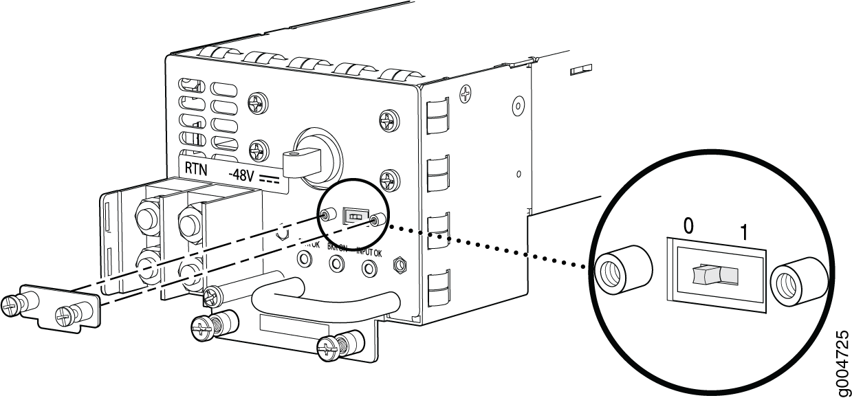
- For a high-capacity DC power supply, check the setting
of the input mode switch. Use a sharp, nonconductive object to slide
the switch to the desired position. Set the input mode switch to position 0 for 60-A input or position 1 for
70-A input. This setting is used by the power management software
and must be set on the power supply. See Figure 4.Figure 4: DC High-Capacity Power Supply Input Mode Switch
- Using both hands, slide the power supply straight into
the chassis until the power supply is fully seated in the chassis
slot. The power supply faceplate should be flush with any adjacent
power supply faceplate (see Figure 5).Figure 5: Installing a DC Power Supply
- Secure each power cable lug to the terminal studs, first
with the washer, then with the nut. Apply between 23 lb-in. (2.6 Nm)
and 25 lb-in. (2.8 Nm) of torque to each nut. (see Figure 6).
- Attach the positive (+) DC source power cable lug to the RTN (return) terminal.
- Attach the negative (–) DC source power cable lug to the –48V (input) terminal.
Figure 6: Connecting DC Power CAUTION:
You must ensure that power connections maintain the proper polarity. The power source cables might be labeled (+) and (–) to indicate their polarity. There is no standard color coding for DC power cables. The color coding used by the external DC power source at your site determines the color coding for the leads on the power cables that attach to the terminal studs on each power supply.
Note:The DC power supplies in PEM0 and PEM1 must be powered by dedicated power feeds derived from feed A, and the DC power supplies in PEM2 and PEM3 must be powered by dedicated power feeds derived from feed B. This configuration provides the commonly deployed A/B feed redundancy for the system.
An SCB must be present for the PWR OK LED to go on.
Replacing an SRX5600 Firewall DC Power Supply Cable
To replace an SRX5600 Firewall DC power supply cable, perform the following procedures:
- Disconnecting an SRX5600 Firewall DC Power Supply Cable
- Connecting an SRX5600 Firewall DC Power Supply Cable
Disconnecting an SRX5600 Firewall DC Power Supply Cable
To remove a power cable from a DC power supply:
- Attach an electrostatic discharge (ESD) grounding strap to your bare wrist and connect the strap to an approved site ESD grounding point.
- Switch off the external circuit breakers for all the cables attached to the power supply. Make sure that the voltage across the DC power source cable leads is 0 V and that there is no chance that the cables might become active during the removal process.
- Remove the power cable from the DC power source.
- Attach an electrostatic discharge (ESD) grounding strap to your bare wrist, and connect the strap to one of the ESD points on the chassis.
- Switch the circuit breaker on the power supply faceplate to the OFF position O.
- Remove the clear plastic cover protecting the terminal studs on the faceplate.
- Remove the nut and washer from the terminal studs. (Use a 7/16–in. nut driver or pliers.)
- Remove the cable lug from the terminal studs.
- Loosen the captive screws on the power supply faceplate.
- Carefully move the power cable out of the way.
Connecting an SRX5600 Firewall DC Power Supply Cable
To install a replacement power cable for a DC power supply (see Figure 7):
Upgrading an SRX5600 Firewall from Standard-Capacity to High-Capacity Power Supplies
You can replace the standard-capacity power supplies in the SRX5600 Firewall with either two or four high-capacity power supplies of the same input type (AC or DC). Two high-capacity power supplies provide adequate power for a fully loaded chassis; installing four high-capacity power supplies provides redundancy in case one power supply in either zone fails. You do not need to power off the device to upgrade to high-capacity power supplies.
The firewall cannot be powered from standard-capacity and high-capacity power supplies simultaneously. The one exception is during the process of replacing standard-capacity power supplies with high-capacity power supplies, when it is permissible to have both types installed briefly.
The firewall cannot be powered from AC and DC power supplies simultaneously. The first type of power supply detected by the firewall when initially powered on determines the type of power supply allowed by the firewall. All installed power supplies of the other type are disabled by the firewall. If you install a power supply of the other type while the firewall is operating, the firewall disables the power supply and generates an alarm.
The following procedures describe how to upgrade from standard-capacity power supplies to high-capacity power supplies of the same input type (AC or DC) without interrupting power to the firewall components. Choose the procedure that matches your firewall configuration:
To upgrade a firewall that has three or four standard-capacity AC power supplies to two or four high-capacity AC power supplies:
Limit to five minutes or less the time during which standard-capacity AC power supplies and high-capacity AC power supplies are installed in the firewall at the same time.
- Ensure that the firewall is running Junos OS Release 12.1X44-D10 or later. Earlier Junos OS releases do not recognize high-capacity DC power supplies.
- If you have not already done so, replace the standard-capacity fan tray with a high-capacity fan tray. For more information, see Replacing the SRX5600 Firewall Fan Tray.
- Check the LEDs on all of the installed power supply faceplates to ensure that they are operating properly.
- If there are four standard-capacity AC power supplies installed, remove the standard-capacity AC power supply installed in the PEM0 slot. See Removing an SRX5600 Firewall AC Power Supply for instructions on removing AC power supplies. If there are only three standard-capacity AC power supplies installed in the firewall, proceed to the next step.
- Install a high-capacity AC power supply in the vacant slot in the back of the chassis. See Installing an SRX5600 Firewall AC Power Supply for instructions on installing AC power supplies.
- Check the LEDs on the high-capacity AC power supply faceplate to ensure that it is operating properly.
- Remove the standard-capacity AC power supply from any other PEM slot in the chassis. See Removing an SRX5600 Firewall AC Power Supply for instructions on removing AC power supplies.
- Install a high-capacity AC power supply in the slot you vacated in Step 7. See Installing an SRX5600 Firewall AC Power Supply for instructions on installing AC power supplies.
- Check the LEDs on both high-capacity AC power supply faceplates to ensure that they are operating properly.
- Remove the remaining two standard-capacity AC power supply from the firewall. See Removing an SRX5600 Firewall AC Power Supply for instructions on removing AC power supplies.
- If you are upgrading to four high-capacity AC power supplies to achieve 2+2 redundancy, install high-capacity AC power supplies in the slots you vacated in Step 10. See Installing an SRX5600 Firewall AC Power Supply for instructions on installing AC power supplies.
- Check the LEDs on all installed high-capacity AC power supply faceplates to ensure that they are operating properly.
To upgrade a firewall that has two standard-capacity DC power supplies to two or four high-capacity DC power supplies:
-
Ensure that the firewall is running Junos OS Release 12.1X44-D10 or later. Earlier Junos OS releases do not recognize high-capacity DC power supplies.
-
If you have not already done so, replace the standard-capacity fan tray with a high-capacity fan tray. For more information, see Replacing the SRX5600 Firewall Fan Tray.
-
Install high-capacity DC power supplies in the two empty PEM slots in the back of the chassis. See Installing an SRX5600 Firewall AC Power Supply for instructions on installing DC power supplies.
Check the LEDs on the faceplate of each of the new power supplies to confirm that they are operating properly.
-
Remove both of the standard-capacity power supplies from the Firewall. See Removing an SRX5600 Firewall AC Power Supply for instructions on removing DC power supplies.
If you are installing four high-capacity DC power supply to achieve 2+2 redundancy, install high-capacity DC power supplies in the slots vacated in Step 5.
Check the LEDs on the faceplate of each of the new power supplies to confirm that they are operating properly.
To upgrade a firewall that has four standard-capacity DC power supplies to two or four high-capacity DC power supplies:
-
Ensure that the Firewall is running Junos OS Release 12.1X44-D10 or later. Earlier Junos OS releases do not recognize high-capacity DC power supplies.
-
If you have not already done so, replace the standard-capacity fan tray with a high-capacity fan tray. For more information, see Replacing the SRX5600 Firewall Fan Tray.
Check the LEDs on all four power supply faceplates to ensure that they are operating properly.
-
Remove the standard-capacity power supply from slot PEM0. See Removing an SRX5600 Firewall AC Power Supply for instructions on removing DC power supplies.
-
Install a high-capacity DC power supply in the PEM0 slot in the back of the chassis. See Installing an SRX5600 Firewall AC Power Supply for instructions on installing DC power supplies.
Repeat Step 4 and Step 5 to replace the standard-capacity DC power supply in the PEM1 slot with a high-capacity DC power supply.
Check the LEDs on the faceplate of each of the new power supplies to confirm that they are operating properly.
-
Remove the two standard-capacity power supplies from the PEM2 and PEM3 slots. See Removing an SRX5600 Firewall AC Power Supply for instructions on removing DC power supplies.
-
If you are upgrading to four high-capacity DC power supplies to achieve 2+2 redundancy, install high-capacity DC power supplies in the PEM2 and PEM3 slots. See Installing an SRX5600 Firewall AC Power Supply for instructions on installing DC power supplies.
Check the LEDs on the faceplate of each of the new power supplies to confirm that they are operating properly.