ON THIS PAGE
Overview of Installing the SRX5600 Firewall Without a Mechanical Lift
Tools Required to Install the SRX5600 Firewall Without a Mechanical Lift
Removing Components from the SRX5600 Chassis Before Installing It Without a Lift
Installing the SRX5600 Firewall Chassis in the Rack Manually
Reinstalling Components in the SRX5600 Firewall Chassis After Installing It Without a Lift
Installing the SRX5600 Without a Mechanical Lift
Overview of Installing the SRX5600 Firewall Without a Mechanical Lift
If you cannot use a mechanical lift to install the firewall (the preferred method), you can install it manually. Before installing the firewall manually, you must first remove components from the chassis, and you must reinstall the components once the firewall is installed in the rack. At least two people are needed to safely lift the chassis into the rack or cabinet. With components removed, the chassis weighs approximately 65 lb (29 kg).
Before installing the firewall in the rack, read the safety information in Chassis Lifting Guidelines. Remove the firewall from the shipping container as described in Unpacking the SRX5600 Firewall . Install the mounting hardware as described in Installing the SRX5600 Firewall Mounting Hardware for a Rack or Cabinet.
An optional air deflector kit is available that lets you install the SRX5600 Firewall in a hot aisle/cold aisle ventilation environment.
Tools Required to Install the SRX5600 Firewall Without a Mechanical Lift
To install the firewall, you need the following tools and parts:
Phillips (+) screwdrivers, numbers 1 and 2
7/16-in. (11 mm) nut driver
ESD grounding wrist strap
Removing Components from the SRX5600 Chassis Before Installing It Without a Lift
If you cannot use a mechanical lift to install the firewall (the preferred method), you can install it manually. Before installing the firewall manually, you must first remove components from the chassis, and reinstall the components the chassis is installed in the rack. With components removed, the chassis weighs approximately 65 lb (29 kg).
- Removing the Power Supplies Before Installing the SRX5600 Firewall Without a Lift
- Removing the Fan Tray Before Installing an SRX5600 Firewall Without a Lift
- Removing Cards Before Installing an SRX5600 Firewall Without a Lift
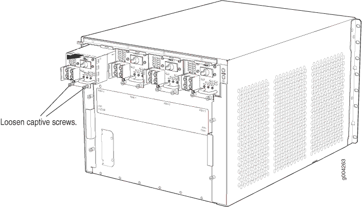
Removing the Power Supplies Before Installing the SRX5600 Firewall Without a Lift
Remove the leftmost power supply first and then work your way to the right. To remove the AC or DC power supplies for each power supply (see Figure 1):
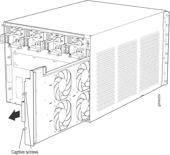
Removing the Fan Tray Before Installing an SRX5600 Firewall Without a Lift
To remove the fan tray (see Figure 2):
- Attach an electrostatic discharge (ESD) grounding strap to your bare wrist, and connect the strap to one of the ESD points on the chassis.
- Loosen the captive screws on the fan tray faceplate.
- Grasp the fan tray handle and pull it out approximately 1 to 3 inches.
- Press the latch located on the inside of the fan tray to release it from the chassis.
- Place one hand under the fan tray to support it and pull the fan tray completely out of the chassis.
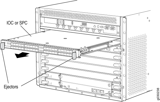
Removing Cards Before Installing an SRX5600 Firewall Without a Lift
The firewall holds up to six cards (IOCs, Flex IOCs, MPCs, SCBs, and SPCs), which are installed horizontally in the front of the device. Each card weighs up to 18.3 lb (8.3 kg), be prepared to accept its full weight.
To remove a card (see Figure 3):
Installing the SRX5600 Firewall Chassis in the Rack Manually
To install the device in the rack (see Figure 4):
If you are installing more than one firewall in a rack, install the lowest one first. Installing a firewall in an upper position in a rack or cabinet requires a lift.
Before front mounting the firewall in a rack, have a qualified technician verify that the rack is strong enough to support the firewall’s weight and is adequately supported at the installation site.
Lifting the chassis and mounting it in a rack requires two people. The empty chassis weighs approximately 65 lb (29 kg).
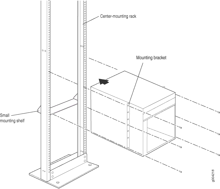
This illustration depicts the firewall being installed in an open-frame rack.
Reinstalling Components in the SRX5600 Firewall Chassis After Installing It Without a Lift
After the firewall is installed in the rack, reinstall the removed components before booting and configuring the firewall. You reinstall components first in the rear of the chassis, and then in the front:
- Reinstalling Power Supplies After Installing the SRX5600 Firewall Without a Lift
- Reinstalling the Fan Tray After Installing the SRX5600 Firewall Without a Lift
- Reinstalling SCBs After Installing the SRX5600 Firewall Without a Lift
- Reinstalling IOCs, Flex IOCs, and SPCs After Installing the SRX5600 Firewall Without a Lift
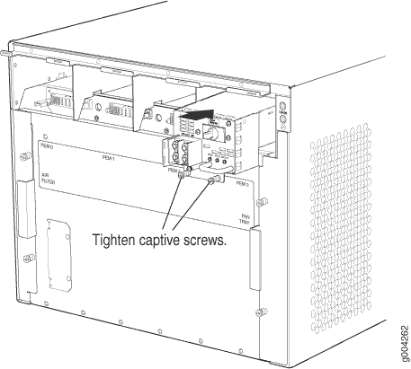
Reinstalling Power Supplies After Installing the SRX5600 Firewall Without a Lift
Reinstall the rightmost power supply first and then work your way to the left. To reinstall the AC or DC power supplies, follow this procedure for each power supply (see Figure 5, which shows the installation of the DC power supplies):
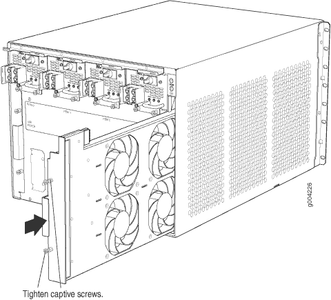
Reinstalling the Fan Tray After Installing the SRX5600 Firewall Without a Lift
To reinstall the fan tray (see Figure 6):
- Attach an electrostatic discharge (ESD) grounding strap to your bare wrist, and connect the strap to one of the ESD points on the chassis.
- Grasp the fan tray on each side and insert it straight into the chassis. Note the correct orientation by the "this side up" label on the top surface of the fan tray.
- Tighten the captive screws on the fan tray faceplate to secure it in the chassis.
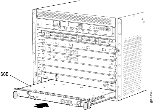
Reinstalling SCBs After Installing the SRX5600 Firewall Without a Lift
To reinstall an SCB (see Figure 7):
Before removing or replacing an SCB, ensure that the ejector handles are stored horizontally and pressed toward the center of the SCB.
- Attach an electrostatic discharge (ESD) grounding strap to your bare wrist, and connect the strap to one of the ESD points on the chassis.
- Carefully align the sides of the SCB with the guides inside the chassis.
- Slide the SCB into the chassis until you feel resistance, carefully ensuring that it is correctly aligned.
- Grasp both ejector handles and rotate them simultaneously clockwise until the SCB is fully seated.
- Place the ejector handles in their proper position, horizontally and toward the center of the board. To avoid blocking the visibility of the LEDs position the ejectors over the PARK icon.
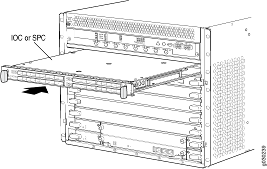
Reinstalling IOCs, Flex IOCs, and SPCs After Installing the SRX5600 Firewall Without a Lift
To reinstall IOCs, Flex IOCs, MPCs, and SPCs, follow this procedure for each card (see Figure 8):
- Attach an ESD grounding strap to your bare wrist, and connect the strap to one of the ESD points on the chassis.
- Place the card on an antistatic mat or remove it from its electrostatic bag.
- Identify the slot on the firewall where it will be installed.
- Verify that each fiber-optic has a rubber safety cap covering the transceiver. If it does not, cover the transceiver with a safety cap.
- Orient the card so that the faceplate faces you.
- Lift the card into place and carefully align the sides of the card with the guides inside the card cage.
- Slide the card all the way into the card cage until you feel resistance.
- Grasp both ejector handles and rotate them clockwise simultaneously until the card is fully seated.