Connecting the SRX4600 to Power
Connecting Earth Ground to an SRX4600 Firewall
To meet safety and electromagnetic interference (EMI) requirements and to ensure proper operation, you must connect the SRX4600 Firewall to earth ground before you connect it to power.
For installations that require a separate grounding conductor to the chassis, you must attach a protective earthing terminal bracket on the mounting bracket on the left front of the firewall to connect to the earth ground ).
You must install the SRX4600 in a restricted-access location and ensure that the chassis is always properly grounded. The SRX4600 has a two-hole protective grounding terminal provided on the chassis. See Figure 1. Under all circumstances, use this grounding connection to ground the chassis. For AC-powered systems, you must also use the grounding wire in the AC power cord along with the two-hole grounding lug connection. This tested system meets or exceeds all applicable EMC regulatory requirements with the two-hole protective grounding terminal.
Before you connect earth ground to the protective earthing terminal of an SRX4600 Firewall, ensure that a licensed electrician has attached an appropriate grounding lug to the grounding cable.
Using a grounding cable with an incorrectly attached lug can damage the firewall.
Mount your firewall in the rack or cabinet before attaching the grounding lug to the firewall. See SRX4600 Firewall Installation Overview.
Ensure that you have the following parts and tools available:
-
Protective earthing terminal bracket (not provided)—This bracket attaches to the firewall chassis through the left front mounting bracket, providing a protective earthing terminal for the firewall.
-
Grounding cable for your firewall (not provided)—The grounding cable must be 14 AWG (2 mm²), minimum 90° C wire, or as permitted by the local code.
-
Grounding lug for your grounding cable (not provided)—The grounding lug required is a Panduit LCD10-10A-L or equivalent.
-
Two SAE 10–32 x 0.375 in. screws with integrated split washers (not provided)—The screws and washers are used to secure the grounding lug to the protective earthing terminal.
-
Socket wrench or screw driver to tighten the screws.
An AC-powered firewall chassis gains additional grounding when you plug the power supply in the firewall into a grounded AC power outlet by using an AC power cord appropriate for your geographical location. See SRX4600 Firewall AC Power Cord Specifications.
To connect earth ground to an SRX4600 Firewall:
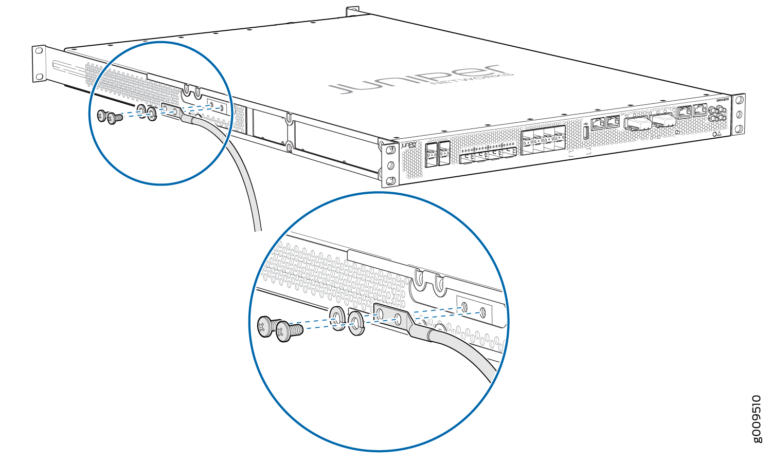
- Secure the grounding lug to the protective earthing terminal
with the two washers and screws. See Figure 1.Figure 1: Connecting a Grounding Cable to an SRX4600 Firewall
Connecting AC Power to an SRX4600 Firewall
Ensure that you have a power cord appropriate for your geographical location available to connect AC power to the firewall.
Before you begin connecting AC power to the firewall:
Ensure that you have taken the necessary precautions to prevent electrostatic discharge (ESD) damage (see Prevention of Electrostatic Discharge Damage).
Ensure that you have connected the firewall chassis to earth ground.
CAUTION:Before you connect power to the firewall, a licensed electrician must attach a cable lug to the grounding and power cables that you supply. A cable with an incorrectly attached lug can damage the firewall (for example, by causing a short circuit).
To meet safety and electromagnetic interference (EMI) requirements and to ensure proper operation, you must connect the chassis to earth ground before you connect it to power. For installations that require a separate grounding conductor to the chassis, use the protective earthing terminal on the firewall chassis to connect to the earth ground. For instructions on connecting earth ground, see Connecting Earth Ground to an SRX4600 Firewall. The firewall gains additional grounding when you plug the power supply in the firewall into a grounded AC power outlet by using the AC power cord appropriate for your geographical location.
Install the power supply in the chassis. For instructions on installing an AC power supply in an SRX4600 Firewall, see Installing the SRX4600 Firewall AC Power Supply.
The SRX4600 Firewall is shipped from the factory with two power supplies. Each power supply is a field-replaceable unit (FRU). You can install replacement power supplies without powering off the firewall or disrupting the firewall function.
Each power supply must be connected to a dedicated power source outlet.
To connect AC power to an SRX4600 Firewall:
Connecting DC Power to an SRX4600 Firewall
Before you begin connecting DC power to the firewall:
Ensure that you have taken the necessary precautions to prevent ESD damage (see Prevention of Electrostatic Discharge Damage).
Ensure that you have connected the firewall chassis to earth ground.
CAUTION:To meet safety and electromagnetic interference (EMI) requirements and to ensure proper operation, you must connect the firewall to earth ground before you connect it to power. For installations that require a separate grounding conductor to the chassis, use the protective earthing terminal on the firewall chassis to connect to earth ground. For instructions on connecting an SRX4600 Firewall to ground using a separate grounding conductor, see Connecting Earth Ground to an SRX4600 Firewall.
Install the power supply in the chassis. See Installing the SRX4600 Firewall DC Power Supply.
Ensure that you have the following parts and tools available to connect DC power to the firewall:
Electrostatic discharge (ESD) grounding strap
Multimeter
The SRX4600 Firewall is shipped from the factory with two power supplies. Each power supply is a field-replaceable unit (FRU). You can install replacement power supplies without powering off the firewall or disrupting the firewall function.
Before you perform DC power procedures, ensure there is no power to the DC circuit. To ensure that all power is off, locate the circuit breaker on the panel board that services the DC circuit, switch the circuit breaker to the off position, and tape the switch handle of the circuit breaker in the off position.
Before you connect power to the firewall, a licensed electrician must attach a cable lug to the grounding and power cables that you supply. A cable with an incorrectly attached lug can damage the firewall (for example, by causing a short circuit).
Each power supply input feed must be connected to a dedicated DC power source outlet.
Ensure that the power cords do not block access to firewall components or drape where people can trip on them.
To connect DC power to the firewall:
-
Install heat-shrink tubing insulation around the power cables.
To install heat-shrink tubing:
-
Slide the tubing over the portion of the cable where it is attached to the lug barrel. Ensure that tubing covers the end of the wire and the barrel of the lug attached to it.
-
Shrink the tubing with a heat gun. Ensure that you heat all sides of the tubing evenly so that it shrinks around the cable tightly.
Figure 2 shows the steps to install heat-shrink tubing.
Note:Do not overheat the tubing.
Figure 2: How to Install Heat-Shrink Tubing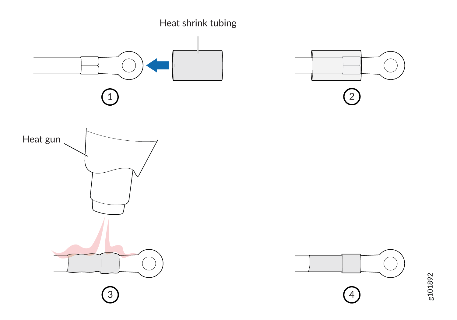
-
-
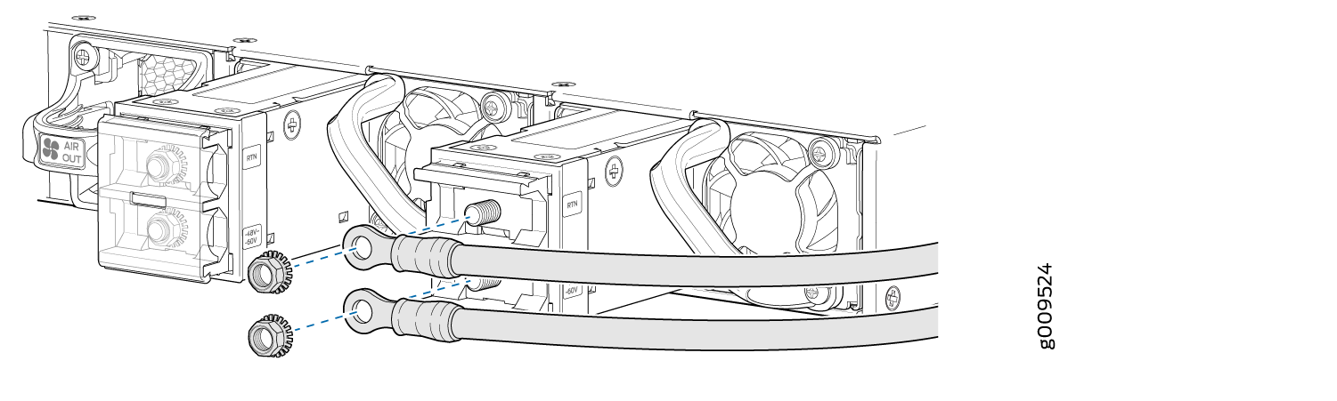
Insert the DC terminal rings into the DC power input terminals and secure the
DC terminal rings with M5 K-nuts, (see Figure 3). Apply between 9 lb-in. (1.1 Nm) and 12 lb-in. (1.3 Nm) of torque to tighten
each M5 K-nuts.
Figure 3: Connecting the Power Supply Cables to a DC power Supply