ON THIS PAGE
Understanding the SRX4600 Firewall Cooling System and Air Flow
The cooling system in an SRX4600 Firewall consists of five fan modules (4+1 redundancy) located at the rear of the chassis.
Fan Module
The five fan modules are numbered 0 through 4 from counting left to right. Each fan module slot has a fan icon next to it. Figure 1 shows the fan module.
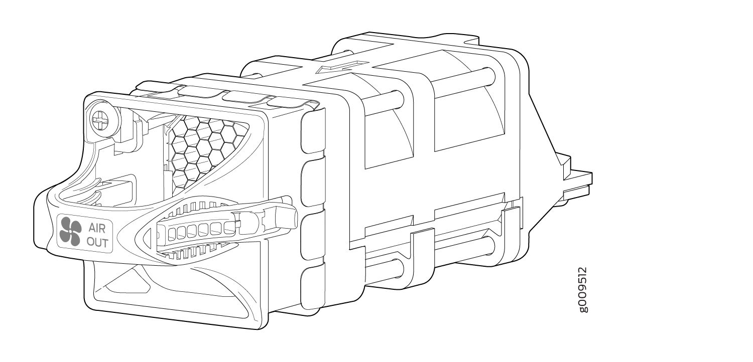
You remove and replace a fan module from the FRU end of the chassis. The firewall continues to operate for a limited period of time (30 seconds) during the replacement of the fan module without thermal shutdown.
All fan modules must be installed for optimal operation of the firewall.
The fan modules are field-replaceable units (FRUs) and can be removed and replaced without powering off the firewall or disrupting firewall functions.
Position the firewall in such a manner that the AIR OUT labels on firewall components are next to the hot aisle.
Under normal operating conditions, the fan modules operate at a moderate speed. Temperature sensors in the chassis monitor the temperature within the chassis.
Fan Module LEDs
Each fan module has a LED next to it.
Figure 2 shows the location of the LED next to the fan module.
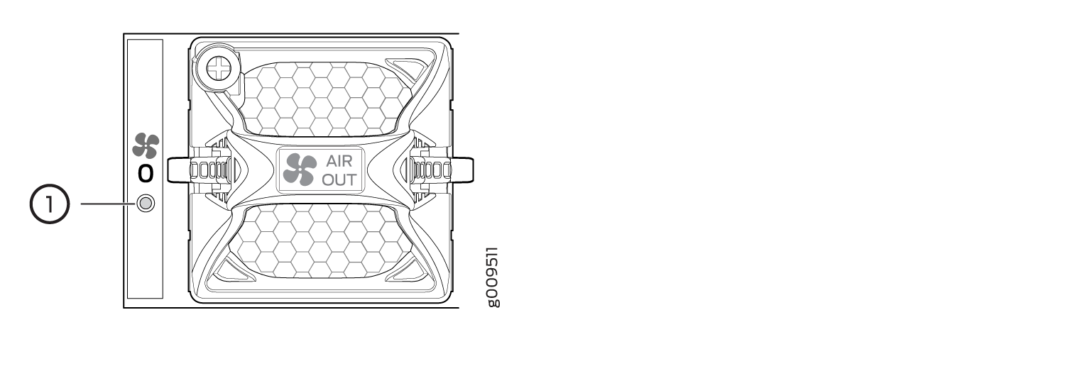
1 — Fan module LED |
Table 1 describes the function of the fan module LED.
|
Name |
Color |
State |
Description |
|---|---|---|---|
|
Fan |
Green |
On steadily |
The fan module is operating normally. The system has verified that the module is engaged, that the airflow is in the correct direction, and that the fan is operating correctly. |
|
Amber |
Blinking |
An error has been detected in the fan module. Replace the fan module as soon as possible. Either the fan has failed or it is seated incorrectly. To maintain proper airflow through the chassis, leave the fan module installed in the chassis until you are ready to replace it. |
The system raises an alarm if a fan module fails or if the ambient temperature inside the chassis rises above the acceptable range. If the temperature inside the chassis rises above the threshold temperature, the system shuts down automatically.
Airflow Through Chassis
The direction of airflow in the chassis is from Port-to-FRU, that is, air comes in through vents on the end with ports and air exhausts out the end with the fans (also known as front-to-back airflow). See Figure 3.
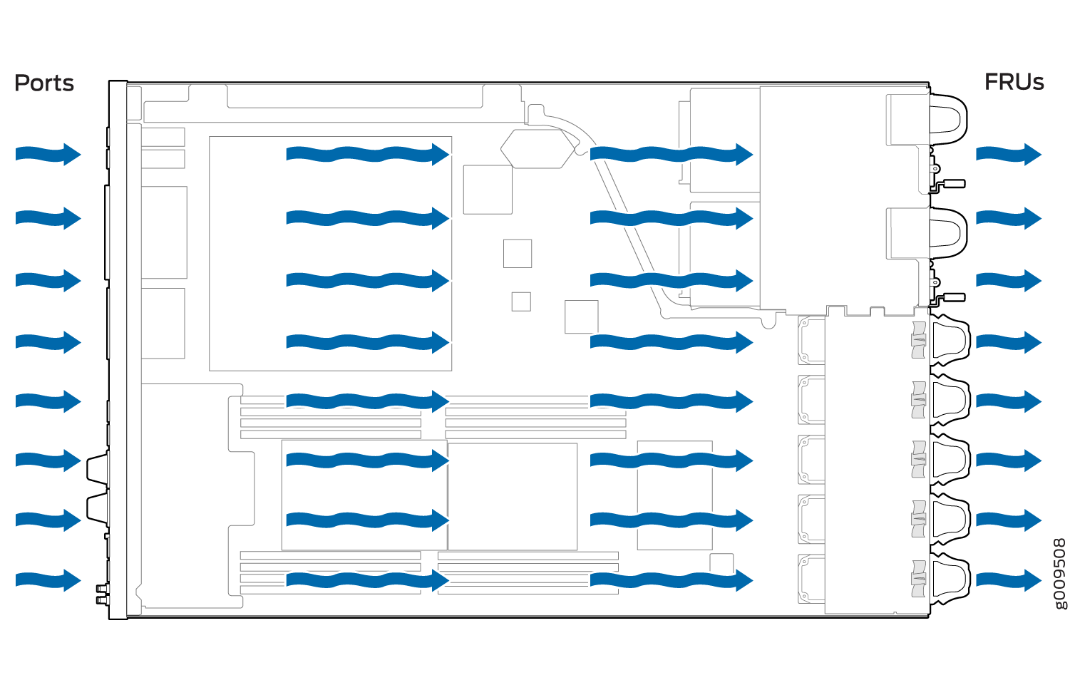
The airflow out (AFO) fan modules draw air through vents on the front of the firewall chassis and exhaust the air through the back of the chassis.