Connecting the SRX4200 to Power
Connecting the SRX4200 Firewall Grounding Cable
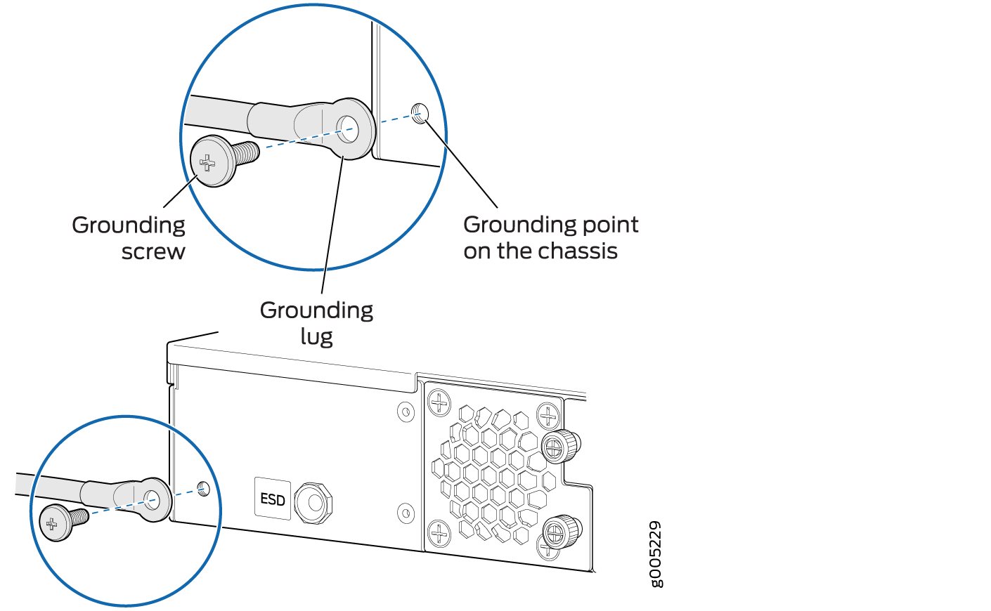
To meet safety and electromagnetic interference (EMI) requirements and to ensure proper operation, the services gateway must be adequately grounded before power is connected. You must provide a grounding lug to connect the services gateway to earth ground.
You ground the services gateway by connecting a grounding cable to earth ground and then attaching it to the chassis grounding point located on the back panel of the device using an M5 x 10 mm grounding screw.
You must install the SRX4200 in a restricted-access location and ensure that the chassis is always properly grounded. The SRX4200 has a single-hole protective grounding terminal provided on the chassis. See Figure 1. Under all circumstances, use this grounding connection to ground the chassis. For AC-powered systems, you must also use the grounding wire in the AC power cord along with the single-hole grounding lug connection. This tested system meets or exceeds all applicable EMC regulatory requirements with the single-hole protective grounding terminal.
Before you connect power to the services gateway, a licensed electrician must attach a cable lug to the grounding cable that you supply. A cable with an incorrectly attached lug can damage the services gateway (for example, by causing a short circuit).
Ensure that you have the following parts and tools available:
-
Electrostatic discharge (ESD) grounding wrist strap
-
Phillips (+) screwdriver, number 2
-
16 AWG single-strand wire grounding cable (green and yellow wire)
-
Grounding lug (ring-type, vinyl-insulated TV14-6R lug, or equivalent)
-
One metric M5 x 10 mm grounding screw
To connect the services gateway to earth ground:
- Secure the grounding cable lug to the grounding point
with the screw. See Figure 1.Figure 1: Connecting the Grounding Cable
When removing the chassis, turn off the power, and disconnect the grounding cable.
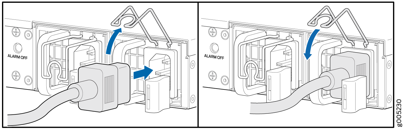
Connecting AC Power to an SRX4200 Firewall
Ensure that you have a power cord appropriate for your geographical location available to connect AC power to an SRX4200 Firewall. Before you begin connecting AC power:
Ensure that you have taken the necessary precautions to prevent electrostatic discharge (ESD) damage.
Ensure that you have connected the device chassis to earth ground.
CAUTION:Before you connect power to the services gateway, a licensed electrician must attach a cable lug to the grounding cable that you supply. A cable with an incorrectly attached lug can damage the device (for example, by causing a short circuit).
To meet safety and electromagnetic interference (EMI) requirements and to ensure proper operation, you must properly ground the services gateway chassis before connecting power.
To connect AC power:
- Push the power cord retainer onto the power cord. See Figure 2.Figure 2: Connecting AC Power
Connecting DC Power to an SRX4200 Firewall
Before you begin connecting DC power to an SRX4200 Firewall:
Ensure that you have taken the necessary precautions to prevent electrostatic discharge (ESD) damage.
Ensure that you have connected the chassis to earth ground.
CAUTION:Before you connect power to the services gateway, a licensed electrician must attach a cable lug to the grounding cable that you supply. A cable with an incorrectly attached lug can damage the device (for example, by causing a short circuit).
To meet safety and electromagnetic interference (EMI) requirements and to ensure proper operation, you must properly ground the services gateway chassis before connecting power.
Ensure that you have the following parts and tools available:
DC power source cables (14–16 AWG) with ring lug (Molex 190700069 or equivalent)
Phillips (+) screwdriver, number 2
Multimeter
To connect DC power:
-
Install heat-shrink tubing insulation around the power cables:
-
Slide the tubing over the portion of the cable where it is attached to the lug barrel. Ensure that the tubing covers the end of the wire and the barrel of the lug attached to it.
-
Shrink the tubing with a heat gun. Ensure that you heat all sides of the tubing evenly so that it shrinks around the cable tightly.
Note:Do not overheat the tubing.
Figure 3 shows how to install heat-shrink tubing.
Figure 3: How to Install Heat-Shrink Tubing
-
-
Connect each power supply to the power source. Secure power source cables to
the power supplies by screwing the ring lugs attached to the cables to the
appropriate terminals by using the screw from the terminals.
-
Secure the ring lug of the positive (+) DC power source cable to the V+ terminal on the DC power supply.
-
Secure the ring lug of the negative (–) DC power source cable to the V– terminal on the DC power supply.
Figure 4: Connecting DC Power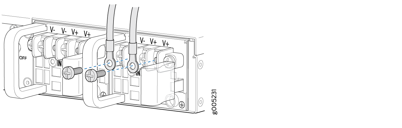
-