SRX4100 Site Guidelines and Requirements
General Site Installation Guidelines
To plan and create an acceptable operating environment for your services gateway and prevent environmentally caused equipment failures:
Follow the prescribed electrostatic discharge (ESD) prevention procedures to prevent damaging the equipment. Static discharge can cause components to fail completely or intermittently over time.
Follow prescribed airflow guidelines to ensure that the cooling system functions properly. The airflow around the chassis must be unrestricted. Allow sufficient clearance between the front and back of the chassis and adjacent equipment. Ensure that there is adequate circulation in the installation location.
Keep the area around the chassis clear and free from dust.
SRX4100 Firewall Environmental Specifications
Table 1 provides the required environmental conditions for normal SRX4100 Firewall operations. In addition, the site must be as dust-free as possible because dust can clog air intake vents, reducing the efficiency of the cooling system.
Description |
Value |
|---|---|
Altitude |
No performance degradation up to 6,562 feet (2000 meters). |
Relative humidity |
Normal operation ensured in relative humidity range of 5% through 90%, noncondensing. |
Temperature |
|
Site Electrical Wiring Guidelines
Table 2 describes the factors you must consider while planning the electrical wiring at your site.
It is particularly important to provide a properly grounded and shielded environment and to use electrical surge-suppression devices.
Site Wiring Factor |
Guideline |
|---|---|
Signaling limitations |
To ensure that signaling functions optimally:
|
Radio frequency interference (RFI) |
To reduce or eliminate the emission of RFI from your site wiring:
|
Electromagnetic compatibility (EMC) |
Provide a properly grounded and shielded environment and use electrical surge-suppression devices. Strong sources of electromagnetic interference (EMI) can cause the following damage:
Tip:
If your site is susceptible to problems with EMC, particularly from lightning or radio transmitters, you might want to seek expert advice. |
Some ports are designed for use as intrabuilding interfaces only Type 2 or Type 4 ports, the battery return connection is to be treated as an Isolated DC return (that is, DC-I), as defined in GR-1089-CORE and require isolation from the exposed OSP cabling. To comply with NEBS requirements and protect against lightning surges and commercial power disturbances, the intrabuilding port(s) of the device MUST NOT be metallically connected to interfaces that connect to the OSP or its wiring. The intrabuilding port(s) of the device is suitable for connection to intrabuilding or unexposed wiring or cabling only. The addition of primary protectors is not sufficient protection to connect these interfaces metallically to OSP wiring.
SRX4100 Firewall Physical Specifications
The SRX4100 Firewall chassis is a rigid sheet metal structure that houses all the components. Table 3 lists the physical specifications of the SRX4100 Firewall chassis.
Description |
Value |
|---|---|
Chassis height |
1.75 in. (4.45 cm) |
Chassis width |
17.48 in. (44.40 cm) |
Chassis depth |
25 in. (63.50 cm) |
Weight |
|
You can mount the SRX4100 Firewall on a standard 19-in. four-post rack or in a standard 19-in. enclosed cabinet.
See Also
Clearance Requirements for Airflow and Hardware Maintenance for SRX4100 Services Gateways
When planning the installation site, you need to allow sufficient clearance around the services gateway. Consider the following:
For the cooling system to function properly, the airflow around the chassis must be unrestricted. See Figure 1.
Figure 1: Airflow Through the Chassis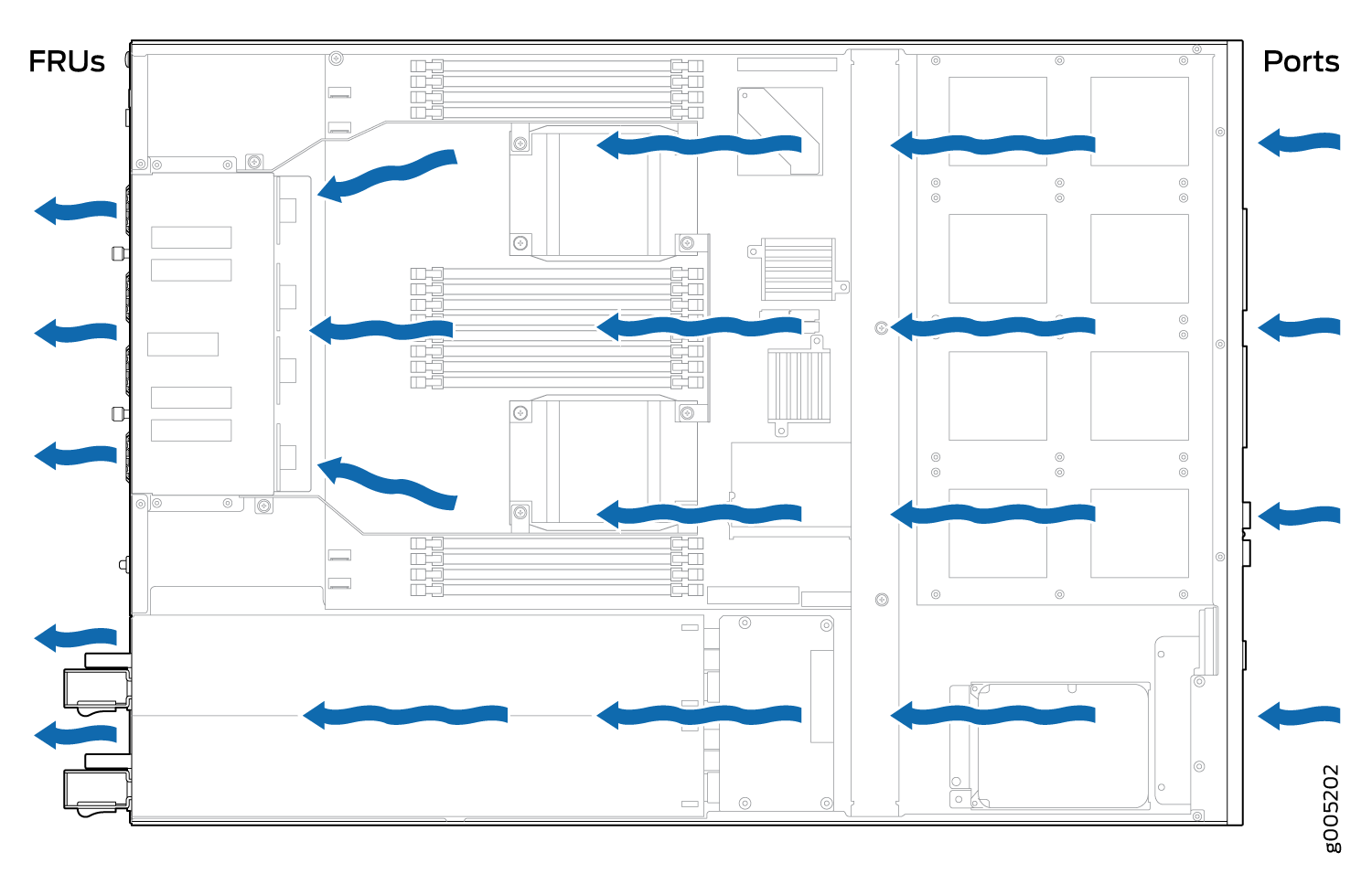
If you are mounting the services gateway on a rack or cabinet along with other equipment, ensure that the exhaust from other equipment does not blow into the intake vents of the chassis.
For service personnel to remove and install hardware components, there must be adequate space at the front and back of the services gateway as indicated in Table 4.
Table 4 provides information about the clearance requirements for maintaining optimum airflow and the distances necessary to facilitate easy maintenance of the services gateway.
Location |
Recommended Clearance |
Requirement for Clearance |
|---|---|---|
Front of the chassis |
34.25 in. (87 cm) |
Space for service personnel to remove and install hardware components |
Rear of the chassis |
17.4 in. (44.2 cm) |
Space for service personnel to remove and install hardware components |
Between front-mounting flange and rack or cabinet edge |
2.5 in. (6.35 cm) |
Space for cable management and organization |
Between both sides of the chassis and any non-heat-producing surface such as a wall or cabinet side |
6.0 in. (15.24 cm) |
Space for the cooling system to function properly and to maintain unrestricted airflow around the chassis |
See Also
SRX4100 Firewall Rack Requirements
The SRX4100 Firewall is designed to be installed on four-post racks. Table 5 provides the rack requirements and specifications for the services gateway.
Rack Requirement |
Guidelines |
|---|---|
Rack type |
Use a four-post rack that provides bracket holes or hole patterns spaced at 1 U (1.75 in. or 4.45 cm) increments and that meets the size and strength requirements to support the weight. A U is the standard rack unit defined in Cabinets, Racks, Panels, and Associated Equipment (document number EIA-310–D) published by the Electronics Industry Association (http://www.eia.org). |
Mounting bracket hole spacing |
The holes in the mounting brackets are spaced at 1 U (1.75 in. or 4.45 cm), so that the device can be mounted in any rack that provides holes spaced at that distance. |
Rack size and strength |
|
Rack connection to building structure |
|
See Also
Cabinet Requirements for SRX4100 Services Gateways
You can install the SRX4100 Firewall in a 19 in. (48.7 cm) cabinet. Table 6 provides the cabinet requirements and specifications.
Cabinet Requirement |
Guideline |
|---|---|
Cabinet size |
You can mount the services gateway in a cabinet that contains a 19-in. rack as defined in Cabinets, Racks, Panels, and Associated Equipment (document number EIA-310–D) published by the Electronics Industry Association (https://www.ecianow.org/eia-technical-standards). |
Cabinet clearance |
|
Cabinet airflow requirements |
When you mount services gateway in a cabinet, you must ensure that ventilation through the cabinet is sufficient to prevent overheating.
|