SRX4100 Chassis
SRX4100 Services Gateway Chassis Overview
The 4100 Services Gateway chassis is a rigid sheet metal structure that houses all the other hardware components. The chassis measures 1.75 in. high, 17.48 in. wide, and 25 in. deep. The chassis installs in standard 600-mm deep (or larger) enclosed cabinets or 19-in. equipment racks.
Before removing or installing components of a functioning services gateway, attach an electrostatic discharge (ESD) strap to an ESD point and place the other end of the strap around your bare wrist. Failure to use an ESD strap could result in damage to the device.
The services gateway must be connected to earth ground during normal operation.
SRX4100 Firewall Front Panel
Figure 1 shows the front panel of the SRX4100 Firewall.
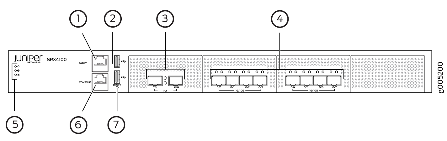
Table 1 lists the components on the front panel of the services gateway.
|
Number |
Component |
Description |
|---|---|---|
|
1 |
Management port |
Gigabit Ethernet port to connect to the device over the network. |
|
2 |
USB ports |
Two USB 2.0 ports that accept a USB storage device. |
|
3 |
HA ports |
Two 1-Gigabit Ethernet/10-Gigabit Ethernet ports, CTL (control port) and FAB (fabric port), to synchronize data and maintain state information in a chassis cluster setup. These ports support enhanced small form-factor pluggable (SFP/SFP+) transceivers. |
|
4 |
SFP+ ports |
Eight 1-Gigabit Ethernet/10-Gigabit Ethernet SFP+ ports for network traffic. Note:
Ports 0/0 to 0/3 are part of a port group that is connected to one CPU socket. Similarly, ports 0/4 to 0/7 form another port group and are connected to a different CPU socket. When choosing ports for network traffic, ensure that you use the ports equally from each socket so that the traffic is evenly distributed, and the overall CPU load is balanced. For example, if you plan to use two ports, then choose one port from each socket. If the network traffic passes only through the ports in one group, you might encounter performance and load balancing issues. |
|
5 |
LEDs |
Indicate component and system status at a glance. |
|
6 |
Console port |
Connects a laptop to the services gateway for CLI management. The port uses an RJ-45 serial connection, is configured as DTE, and supports the RS-232 (EIA-232) standard. |
|
7 |
Reset button |
Returns the services gateway to the factory-default configuration. |
Chassis Status LEDs
Figure 2 shows the LEDs on the front panel, and Table 2 describes the LEDs.
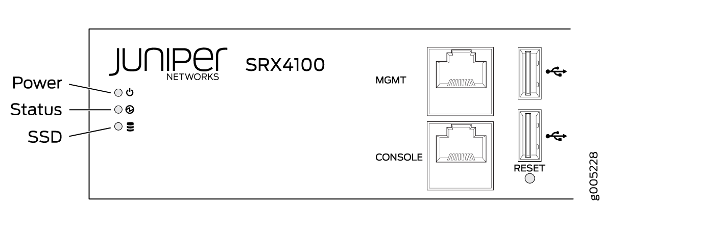
|
LED |
Description |
|---|---|
|
Power |
|
|
Status |
|
|
SSD |
|
Management Port LEDs
The management port has two LEDs that indicate link activity and status of the management port.
Table 3 describes the LEDs.
|
LED |
Description |
|---|---|
|
Link/Activity (LED on the left) |
|
|
Speed (LED on the right) |
|
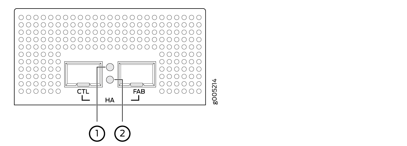
HA Port LEDs
Each HA port has one status LED located between the ports. Figure 3 shows the LEDs. The upper LED (callout 1) displays the status for the port on the right and the lower LED (callout 2) displays the status for the port on the left. Table 4 describes the LEDs.
|
LED |
Description |
|---|---|
|
Status LED |
|
Network Port LEDs
Each SFP+ port has two status LEDs located above the port. Table 5 describes the LEDs. Figure 4 shows the LEDs.
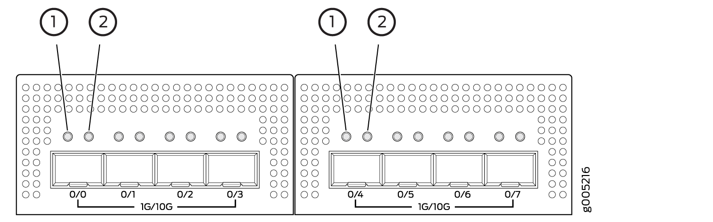
|
Callout |
LED |
Description |
|---|---|---|
|
1 |
Link (LED on the left) |
|
|
2 |
Speed/Activity (LED on the right) |
|
SRX4100 Firewall Back Panel
Figure 5 shows the back panel of the SRX4100 Firewall, and Table 6 lists and describes the back panel components.
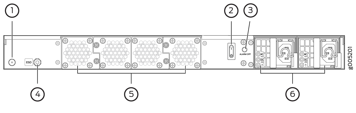
Number |
Component |
Description |
|---|---|---|
1 |
Grounding point |
Connects the services gateway chassis to earth ground. |
2 |
Power switch |
Use the Power switch to power on or power off the services gateway. |
3 |
Alarm Off button |
Use this button to turn off an alarm triggered because of an abnormal DC output voltage caused by any of the following:
|
4 |
ESD point |
For personal safety, while working on the services gateway, use the ESD outlet to plug in an ESD grounding strap to prevent your body from sending static charges to the services gateway. |
5 |
Fan trays |
Four fan trays for cooling the services gateway and its components. Each fan tray contains two fans. Three fan trays are required for proper air flow across the chassis internal components. The fourth fan tray provides redundancy. |
6 |
Power supply |
Two power supply slots. Each power supply contains a power cord outlet. Two 650-W DC or AC power supplies are provided with the services gateway. |