Connecting the SRX345 to Power
Required Tools and Parts for Grounding the SRX345 Services Gateway
To ground and to provide power to the services gateway, you need the following tools:
Phillips (+) screwdrivers, numbers 1 and 2
Electrostatic discharge (ESD) grounding wrist strap
Wire cutters
Connecting the SRX345 Firewall Grounding Cable
To meet safety and electromagnetic interference (EMI) requirements and to ensure proper operation, you must connect the SRX345 Firewall to earth ground before you connect power to the services gateway.
You ground the services gateway by connecting a grounding cable to earth ground and then attaching it to the chassis grounding point located on the side of the device using two #10-32 UNF screws.
You must install the SRX345 in a restricted-access location and ensure that the chassis is always properly grounded. The SRX345 has a two-hole protective grounding terminal provided on the chassis. See Figure 1. Under all circumstances, use this grounding connection to ground the chassis. For AC-powered systems, you must also use the grounding wire in the AC power cord along with the two-hole grounding lug connection. This tested system meets or exceeds all applicable EMC regulatory requirements with the two-hole protective grounding terminal.
You must provide the following items:
-
Screws to secure the grounding lug: Two #10-32 UNF screws, with recommended length of 6 mm through 8 mm
-
Grounding cable: #14 - #10 AWG or as permitted by the local code
-
Cable lug: Panduit LCD10-10A-L or equivalent
Before you connect power to the services gateway, a licensed electrician must attach a cable lug to the grounding and power cables that you supply. A cable with an incorrectly attached lug can damage the services gateway (for example, by causing a short circuit).
To ground the device:
-
Place the grounding cable lug over the grounding point (sized for #10-32 UNF
screws) on the side of the chassis.
Figure 1: Connecting the Grounding Cable to the SRX345 Firewall
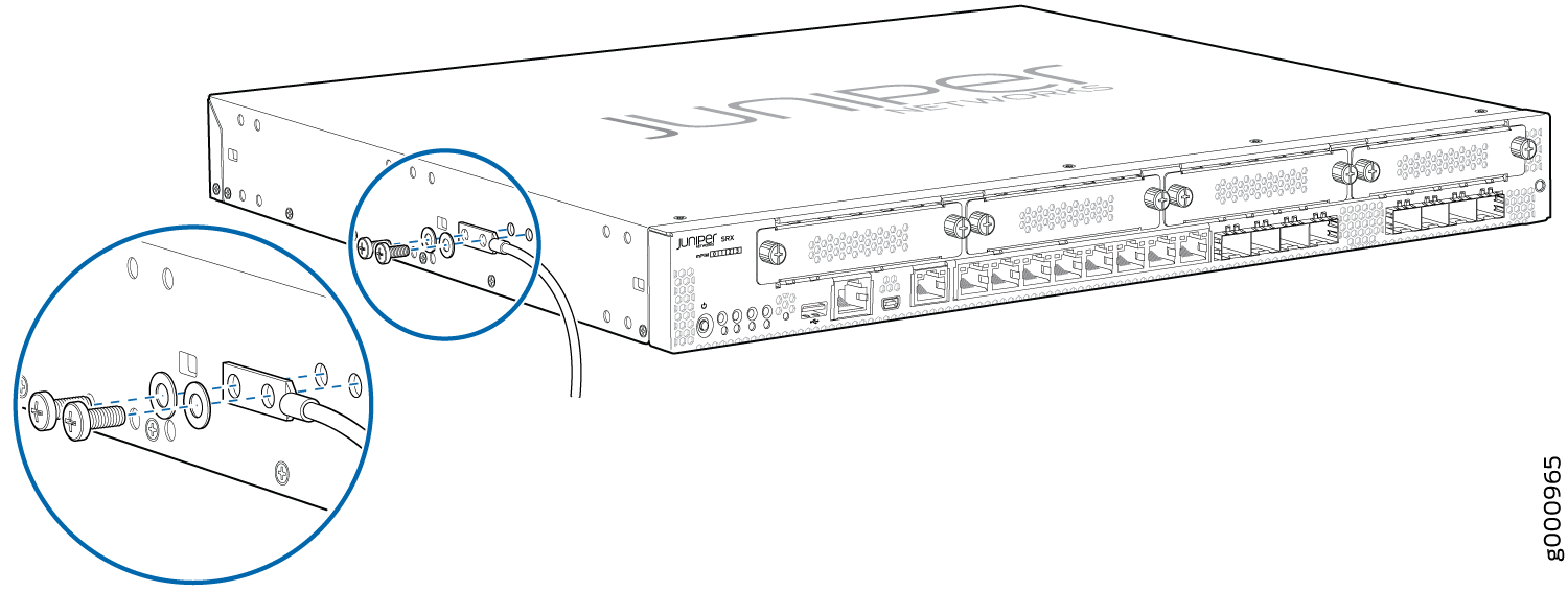
The device should be permanently connected to ground during operation.
Connecting the SRX345 Firewall to an AC Power Supply
You connect AC power to the services gateway by attaching a power cord from the AC power source to the AC appliance inlet located on the power supply faceplate. To connect the device to the power supply:
The services gateway must be connected to earth ground during normal operation. The protective earthing terminal on the side of the chassis is provided to connect the services gateway to ground.
- Insert the power cord plug into an external AC power source
receptacle as shown in Figure 2. Verify
that the power cord does not block the air exhaust and access to services
gateway components or drape where people could trip on it.Figure 2: Connecting the SRX345 Firewall to an AC Power Supply
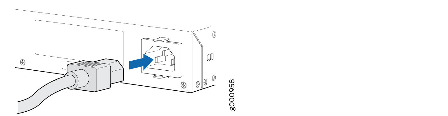
We recommend using a surge protector for the power connection.
Connecting the SRX345 Firewall to a DC Power Supply
You connect DC power to the services gateway by attaching power cables from the external DC power sources to the terminal studs on the rear panel of the services gateway.
To meet safety and electromagnetic interference (EMI) requirements and to ensure proper operation, you must properly ground the services gateway chassis before connecting power. See Connecting the SRX345 Services Gateway Grounding Cable for instructions.
Before performing the following procedure, ensure that power is removed from the DC circuit. To ensure that all power is off, locate the circuit breaker on the panel board that services the DC circuit, switch the circuit breaker to the off position (0), and tape the switch handle of the circuit breaker in the off position.
Before you connect power to the services gateway, a licensed electrician must attach appropriate cable lugs to the grounding and power cables that you use. A cable with an incorrectly attached lug can damage the device (for example, by causing a short circuit).
To connect the DC source power cables to the services gateway:
-
Install heat-shrink tubing insulation around the power cables:
-
Slide the tubing over the portion of the cable where it is attached to the lug barrel. Ensure that the tubing covers the end of the wire and the barrel of the lug attached to it.
-
Shrink the tubing with a heat gun. Ensure that you heat all sides of the tubing evenly so that it shrinks around the cable tightly.
Note:Do not overheat the tubing.
Figure 3 shows how to install heat-shrink tubing.
Figure 3: How to Install Heat-Shrink Tubing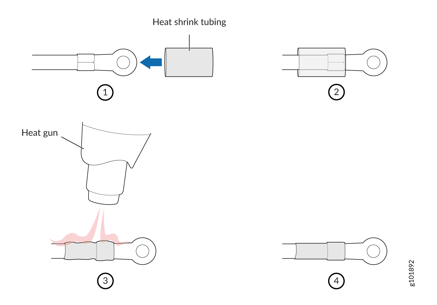
-
-
Secure each power cable lug to the terminals with the square washers and the
screws. Apply between 23 lb-in. (2.6 Nm) and 25 lb-in. (2.8 Nm) of torque to
each screw. See Figure 4
-
Secure the positive (+) DC source power cable lug to the + (return) terminal.
-
Secure the negative (–) DC source power cable lug to a – (input) terminal.
Figure 4: Connecting the SRX345 Firewall to a DC Power Supply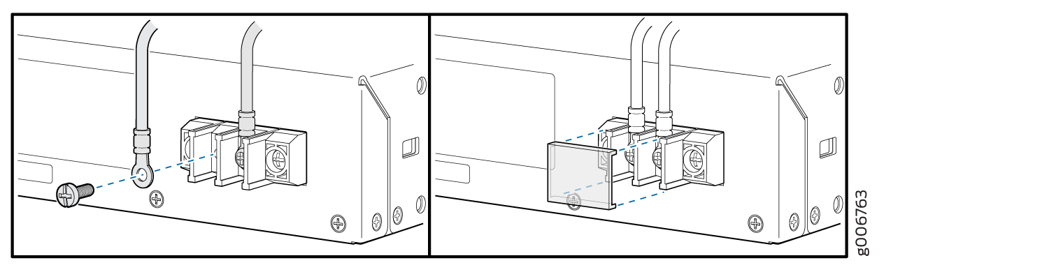
-
Powering On the SRX345 Firewall
To power on the services gateway:
- Insert the power cord plug into the AC power source receptacle.
- Turn on the power to the AC power receptacle. Observe the power supply faceplate LED. If the power supply is installed correctly and functioning normally, the LED glows steady green.
- If you are using a SRX345 Firewall with dual AC power supplies, then repeat steps 1 and 2 for the second power supply.
The device starts automatically as the power supply completes its startup sequence. The PWR LED lights during startup and remains on when the device is operating normally.
After the power supply is turned on, it can take up to 60 seconds for status indicators—such as the STAT and PWR LEDs—to show that the power supply is functioning normally. Ignore error indicators that appear during the first 60 seconds.
When the system is completely powered off and you turn
on the power supply, the device starts as the power supply completes
its startup sequence. If the device finishes starting and you need
to power off the system again, first issue the CLI request system
power-off command.
Powering Off the SRX345 Services Gateway
You can power off the services gateway in one of the following ways:
Graceful shutdown—Press and immediately release the Power button. The device begins gracefully shutting down the operating system and then powers itself off.
CAUTION:Use the graceful shutdown method to power off or reboot the services gateway.
Forced shutdown—Press the Power button and hold it for ten seconds. The device immediately powers itself off without shutting down the operating system.
CAUTION:Use the forced shutdown method as a last resort to recover the services gateway if the services gateway operating system is not responding to the graceful shutdown method.
Do not press the Power button while the device is shutting down.
Forced shutdown can result in data loss and corruption of the file system.
To remove power completely from the device, unplug the power cord or switch off the AC power source.
After powering off a power supply, wait at least 10 seconds before turning it back on. After powering on a power supply, wait at least 10 seconds before turning it off.
The Power button on the services gateway is a standby power switch, which will not turn off the input power to the services gateway.
When you are powering off the device, the CLI displays
the following message: Turning the system power off. You
can now safely remove the power cable to completely power off the
device.
You can use the request system reboot CLI command to schedule a reboot.