Unpacking and Mounting the SRX320
Unpacking the SRX320 Firewall
The SRX320 Firewall is shipped in a cardboard carton and secured with foam packing material. The carton also contains an accessory box and quick-start instructions.
To unpack the SRX320 Firewall:
- Move the cardboard carton to a staging area as close to the installation site as possible, where you have enough room to remove the components from the chassis.
- Position the cardboard carton with the arrows pointing up.
- Carefully open the top of the cardboard carton.
- Remove the foam covering the top of the services gateway.
- Remove the accessory box.
- Verify the parts received against the lists in Verifying Parts Received with the SRX320 Services Gateway.
- Store the brackets and bolts inside the accessory box.
- Save the shipping carton and packing materials in case you need to move or ship the services gateway at a later time.
Verifying Parts Received with the SRX320 Firewall
The SRX320 Firewall shipment package contains a packing list. Check the parts in the shipment against the items on the packing list. The packing list specifies the part numbers and carries a brief description of each part in your order.
If any part is missing, contact a customer service representative.
A fully configured services gateway contains the chassis with installed components, listed in Table 1, and an accessory box, which contains the parts listed in Table 2.
The parts shipped with your services gateway can vary depending on the configuration you ordered. To know the part numbers for ordering the separately orderable mounting kits, see the SRX300 Line of Services Gateways for the Branch Platform Datasheet.
Component |
Quantity |
|---|---|
SRX320 Firewall |
1 |
USB console cable with Type-A and Mini-B USB plugs |
1 |
Documentation Roadmap and Product Warranty |
1 |
Power supply adapter and power cord
|
1 |
Part |
Quantity |
|---|---|
End User License Agreement |
1 |
RoHS Card |
1 |
Installing the SRX320 Firewall on a Desk
You can mount an SRX320 Firewall on a desk or any other level surface horizontally or vertically. The four rubber feet attached to the chassis provide stability. Before mounting an SRX320 Firewall on a desk or other level surface:
Verify that the installation site meets the requirements described in SRX320 Site Preparation Checklist.
Place the desk in its permanent location, allowing adequate clearance for airflow and maintenance, and secure it to the building structure.
The horizontal position is the standard installation position. To install the device in a horizontal position:
- Make sure that the rubber feet are attached to the chassis.
- Place the device on a desk with the Juniper Networks logo, which is embossed on the top cover, facing up.
For information on installing Mini-Physical Interface Modules (Mini-PIMs), see SRX300 Series and SRX550 High Memory Services Gateway Interface Modules Reference.
Installing the SRX320 Firewall on a Wall
You can mount an SRX320 Firewall on a wall. The four rubber feet attached to the chassis provide stability. Before mounting the SRX320 Firewall on a wall:
Verify that the installation site meets the requirements described in SRX320 Site Preparation Checklist.
Verify that you have the following parts available in your wall-mounting kit:
Wall-mounting brackets
Screws
The wall-mounting kit is not shipped with the device and must be ordered separately.
To install the device on a wall:
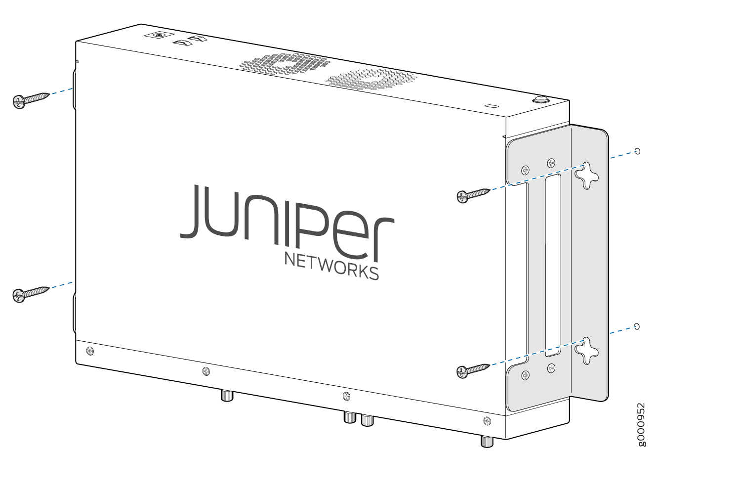
- Position a mounting bracket on each side of the chassis
as shown in Figure 1.Figure 1: Attaching Wall-Mount Brackets
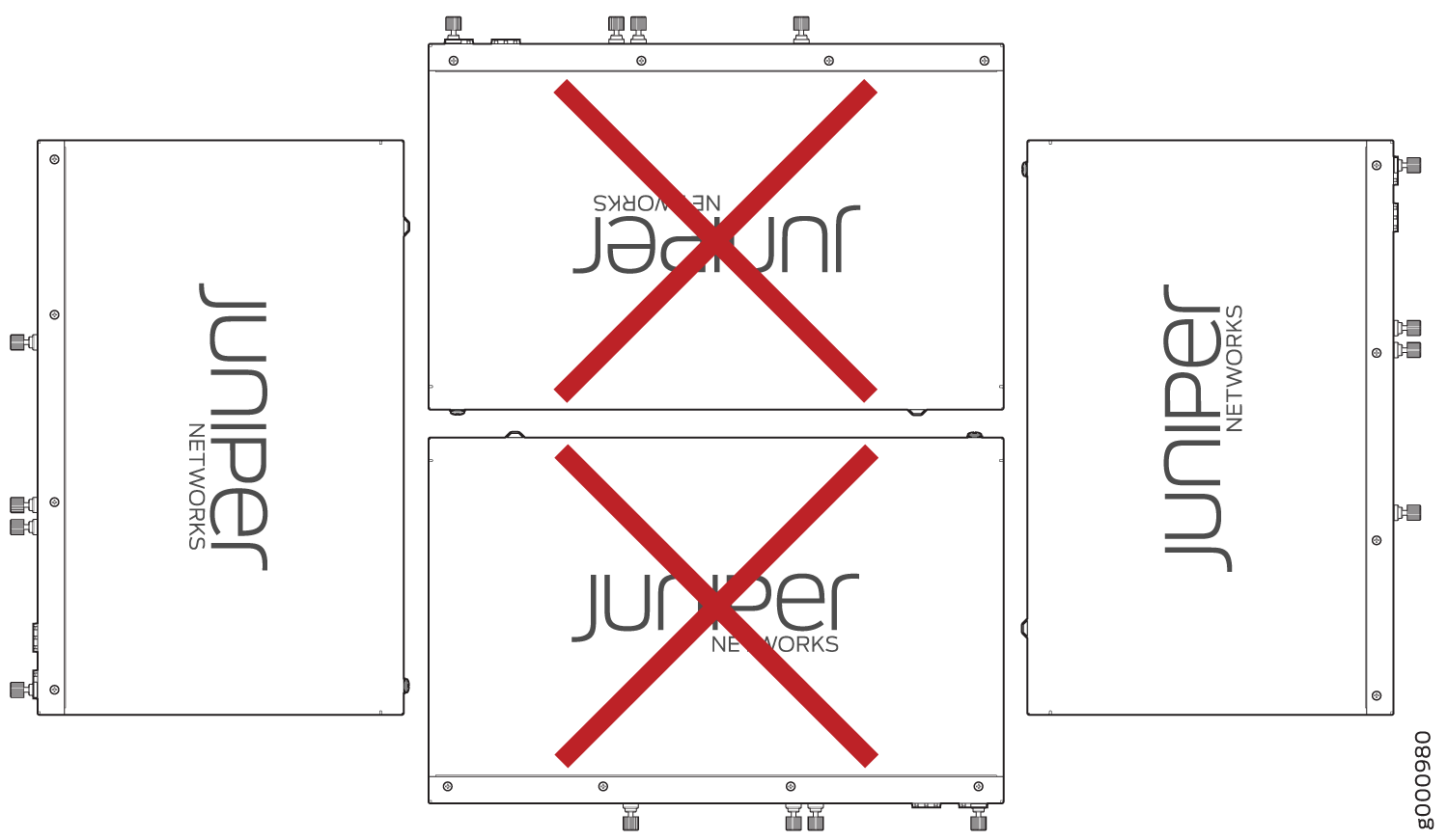
- Have a second person install two pairs of mounting screws
through the bracket holes on either side of the device to secure it
to the wall. Figure 2 shows
the two different orientations in which you can mount the services
gateway on a wall.Figure 2: Orienting the SRX320 Firewall on a Wall
- Verify that the mounting screws on one side are aligned
with the mounting screws on the opposite side and that the device
is level. Figure 3: Mounting the SRX320 Firewall on a Wall
For information on installing Mini-Physical Interface Modules (Mini-PIMs), see SRX300 Series and SRX550 High Memory Services Gateway Interface Modules Reference.
Installing the SRX320 Firewall in a Rack
You can mount an SRX320 Firewall in four-post (telco) racks, enclosed cabinets, and open-frame racks.
The SRX320 Firewall cannot be center-mounted in racks.
Before mounting the SRX320 Firewall in a rack:
Verify that the installation site meets the requirements described in SRX320 Site Preparation Checklist.
Verify that the racks or cabinets meet the specific requirements described in SRX320 Services Gateway Rack-Mounting Requirements and Warnings.
Place the rack or cabinet in its permanent location, allowing adequate clearance for airflow and maintenance, and secure it to the building structure. For more information, see SRX320 Services Gateway Clearance Requirements for Airflow and Hardware Maintenance.
Verify that you have the following parts available in your rack-mounting kit:
Rack-mount tray
Screws
The rack-mounting kit is not shipped with the device and must be ordered separately.
If you are installing multiple devices in one rack, install the lowest one first and proceed upward in the rack. Ensure that the rubber feet from the base of the chassis are removed for rack installation.
To install the device in a rack:
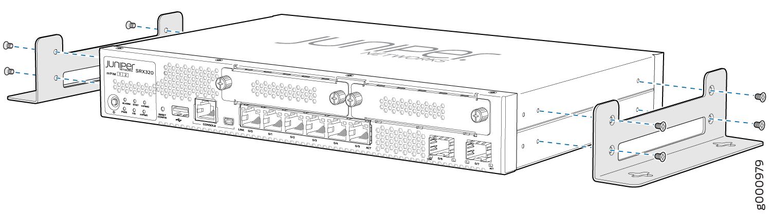
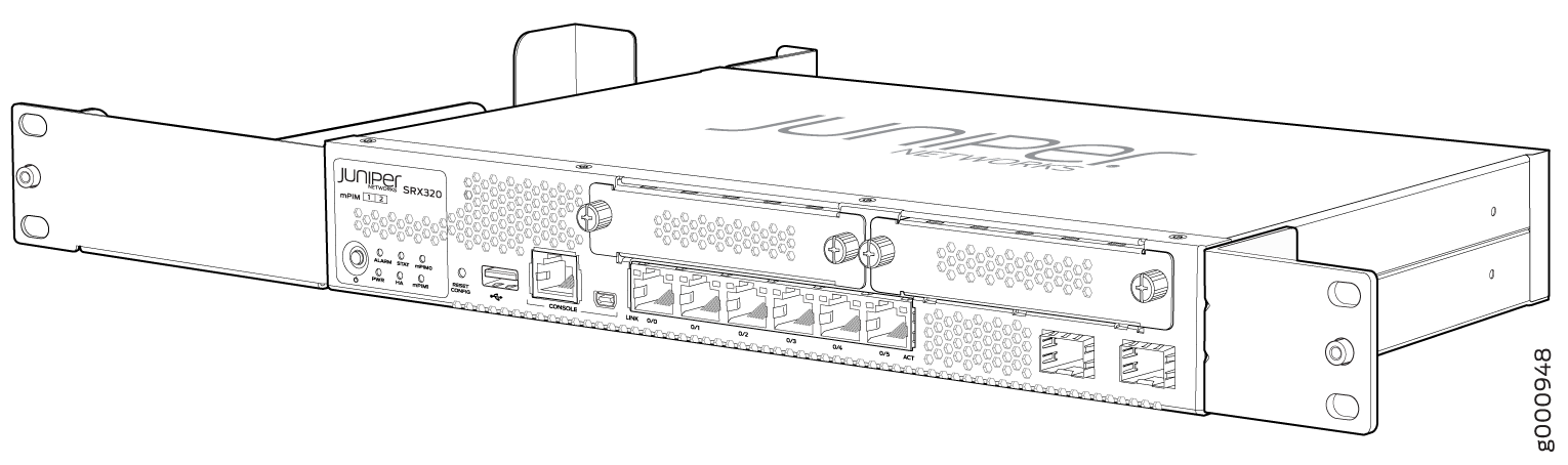
- Position a mounting bracket on each side of the chassis
as shown in Figure 4 and Figure 5.Figure 4: Positioning the Mounting Brackets (75 W Power Supply Adapter)
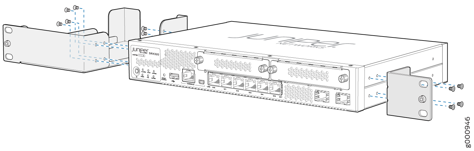 Figure 5: Positioning the Mounting Brackets (280 W Power Supply Adapter)
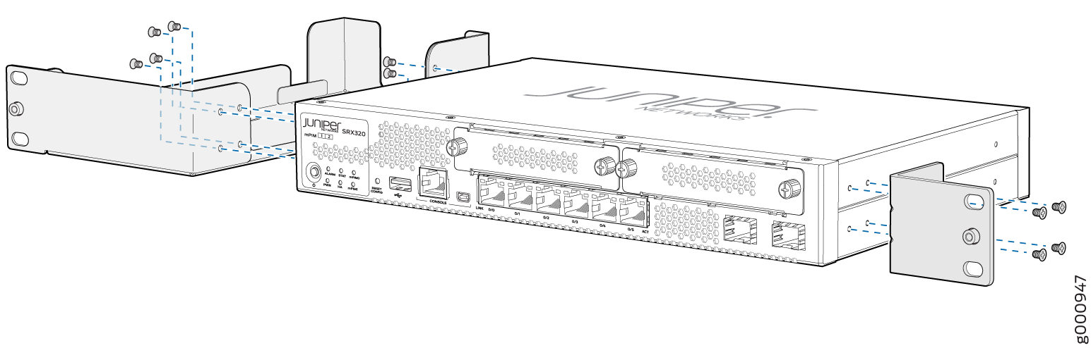
- Use a number-2 Phillips screwdriver to install the screws
that secure the mounting brackets and power supply adapter tray to
the chassis as shown in Figure 6.Figure 6: Securing the Mounting Brackets
- Place the power supply adapter in the tray as shown in Figure 7.Note:
The 280 W power adapter for the PoE model is more than 1 RU tall. When installing the PoE model in a rack, note that you will not be able to install devices in the adjacent slots in a rack.
Figure 7: Positioning the Power Supply Adapter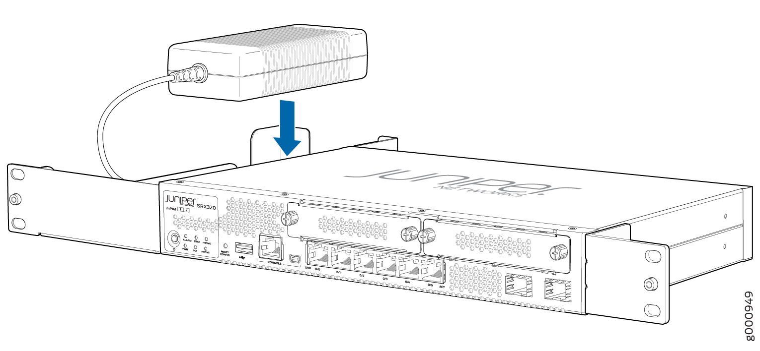
- Align the bottom hole in each mounting bracket with a
hole in each rack rail as shown in Figure 8 and Figure 9, making
sure the chassis is level.Figure 8: Positioning the SRX320 Firewall (PoE Model with 280 W Power Supply Adapter) in a Rack
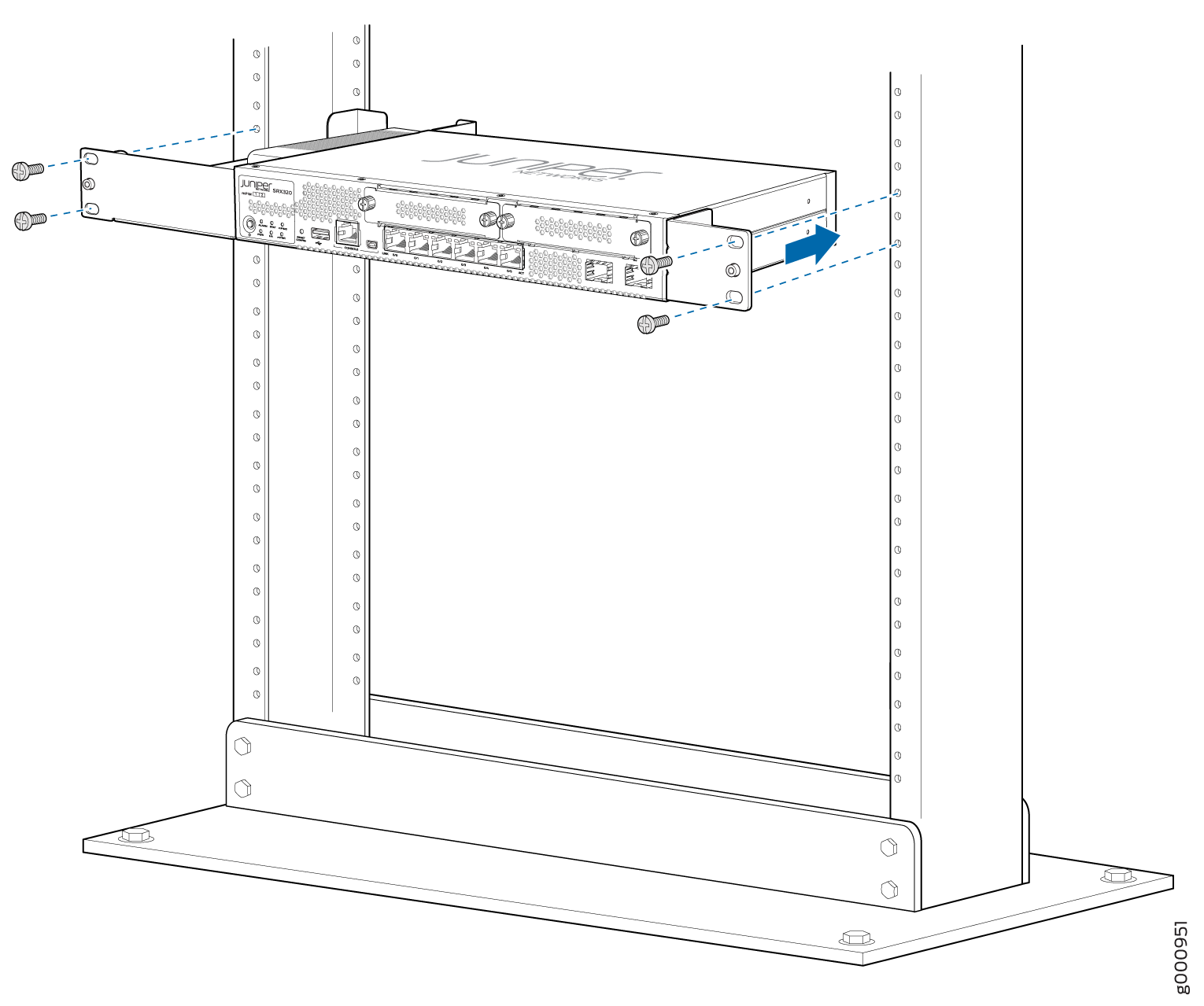 Figure 9: Positioning the SRX320 Firewall (with 75 W Power Supply Adapter) in a Rack
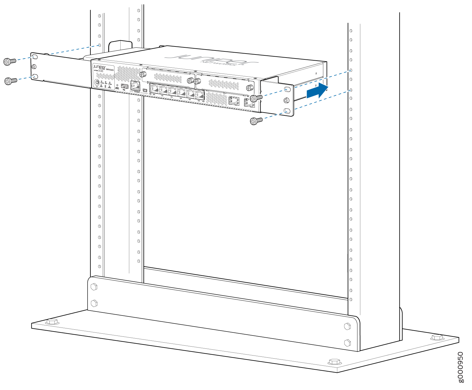
For information on installing Mini-Physical Interface Modules (Mini-PIMs), see SRX300 Series and SRX550 High Memory Services Gateway Interface Modules Reference.