SRX300 Chassis
SRX300 Firewall Chassis Overview
The SRX300 Firewall chassis weighs 4.38 lb. and measures 1.37 in. high, 12.63 in. wide, and 7.52 in. deep.
Before removing or installing components of a functioning services gateway, attach an electrostatic discharge (ESD) strap to an ESD point and place the other end of the strap around your bare wrist. Failure to use an ESD strap could result in damage to the device.
The services gateway must be connected to earth ground during normal operation. The protective earthing terminal on the rear of the chassis is provided to connect the services gateway to ground.
Understanding the SRX300 Firewall Front Panel
Figure 1 shows the front panel of the SRX300 Firewall.
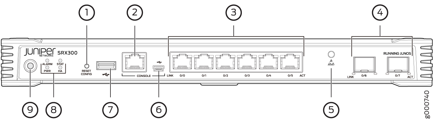
Table 1 provides details about the front panel components.
|
Number |
Component |
Description |
|---|---|---|
|
1 |
Reset Config button |
Returns the services gateway to the rescue configuration or the factory-default configuration. |
|
2 |
Serial Console port |
Connects a laptop to the services gateway for CLI management. The port uses an RJ-45 serial connection and supports the RS-232 (EIA-232) standard. |
|
3 |
1-GbE Ethernet ports |
Six LAN ports (0/0 to 0/5) The ports have the following characteristics:
The ports can be used to:
|
|
4 |
1-GbE small form-factor pluggable (SFP) ports |
Two 1-GbE MACsec-capable SFP ports for network traffic. |
|
5 |
ESD point |
For personal safety, while working on the services gateway, use the ESD outlet to plug in an ESD grounding strap to prevent your body from sending static charges to the services gateway. |
|
6 |
Mini-USB console port |
Connects a laptop to the services gateway for CLI management through a USB interface. The port accepts a Mini-B type USB cable plug. A USB cable with Mini-B and Type A USB plugs is supplied with the services gateway. To use the mini-USB console port, you must download a USB driver to the management device from the Downloads page at https://www.juniper.net/support/downloads/?p=junos-srx#sw. To download the driver for Windows OS, select 6.5 from the Version drop-down list. To download the driver for Mac OS, select 4.10 from the Version drop-down list. |
|
7 |
USB port |
The services gateway has one USB port that accepts a USB storage device. |
|
8 |
LEDs |
Indicates component and system status at a glance. |
|
9 |
Power button |
Use the Power button to power on or power off the services gateway. |
Figure 2 shows the LEDs on the front panel.
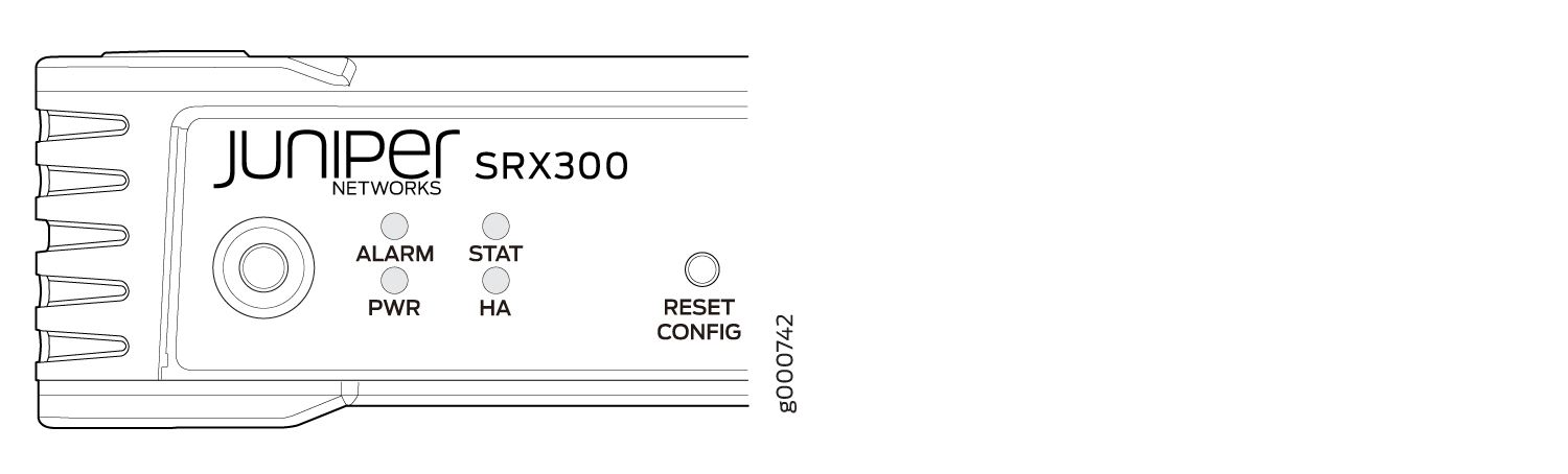
Table 2 lists the front panel LEDs.
|
Component |
Description |
|---|---|
|
ALARM |
|
|
STAT |
|
|
PWR |
|
|
HA |
|
Network Port LEDs
The SFP and Ethernet ports have two status LEDs, LINK and ACT, located above the port.
|
LED |
Description |
|---|---|
|
LINK (LED on the left) |
|
|
ACT (LED on the right) |
|
Understanding the SRX300 Firewall Back Panel
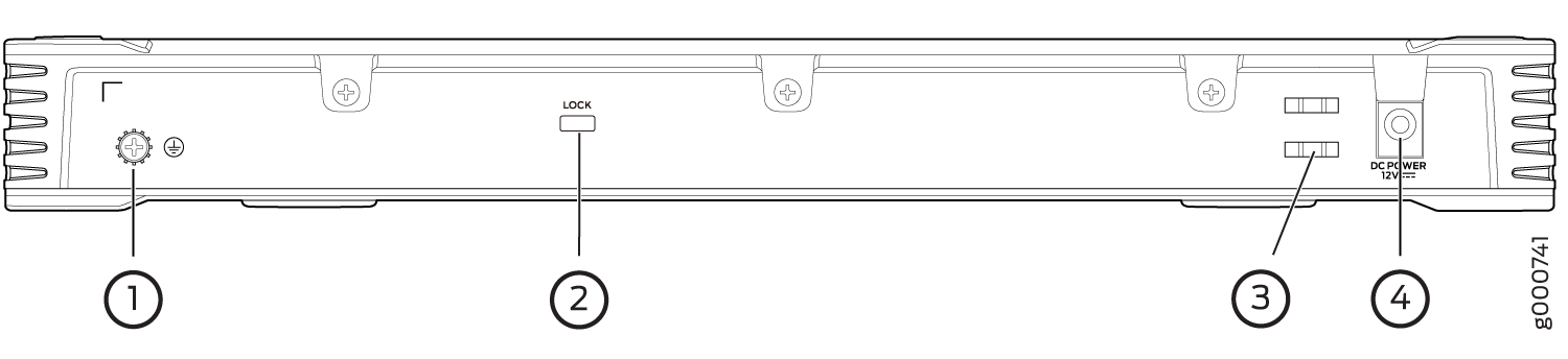
Figure 3 shows the back panel of the SRX300 Firewall and Table 4 lists the back panel components.
|
Number |
Component |
Description |
|---|---|---|
|
1 |
Grounding point |
Connects the services gateway chassis to earth ground (optional). Note:
We recommend connecting the services gateway to ground if required. |
|
2 |
Lock |
Provides the capability to lock and secure the device at the installation site. |
|
3 |
Cable tie holder |
Secures the DC power cord connection to the adapter. |
|
4 |
Power supply input |
Connects the services gateway to the external power supply. |