Wi-Fi Mini-Physical Interface Module
Wi-Fi Mini-Physical Interface Module Overview
The Wi-Fi Mini-Physical Interface Module (Mini-PIM) for branch SRX Series Firewalls provides a branch-in-a-box solution (which includes an SRX Series Firewall, LTE, and wi-fi) for retail and small office deployments. The Mini-PIM has an embedded enterprise-class wireless system-on-chip (SOC) that supports the 802.11ac Wave 2 wireless standards. The Mini-PIM is backward-compatible with 802.11a, 802.11b, 802.11g, and 802.11n.
The Mini-PIM supports the following key features:
2x2 MU-MIMO—Enables transmission of data to multiple clients simultaneously.
Dual radios—Provides concurrent dual bands of 2.4 GHz and 5 GHz. The radios operate in any one of the supported radio modes. You can configure each radio to support connectivity from one type of client or different types of clients.
Virtual access points (VAPs)—Allows you to segment the WLAN into multiple broadcast domains that are the wireless equivalent of Ethernet VLANs. A single access point is segregated into multiple individual VAPs, simulating multiple access points in a single system.
Note:You can configure up to eight VAPs on each radio.
Configurable transmit power—Enables you to configure the transmit power for each radio on a percentage basis. By default, the Mini-PIM assigns 100 percent power to each radio at startup to provide maximum coverage.
Wireless security for client authentication—The Mini-PIM supports the following authentication methods:
Wi-Fi Protected Access (WPA) Personal, which includes AES-CCMP with preshared key authentication.
WPA Enterprise, which includes AES-CCMP with RADIUS server authentication.
MAC authentication, where wireless clients are allowed or denied network access based on their MAC address.
The Mini-PIM is supported on the SRX320, SRX340, SRX345, and SRX550M devices and can coexist with other Mini-PIMs supported on these devices.
Front Panel Components
Figure 1 shows the front panel of the Wi-Fi Mini-PIM.
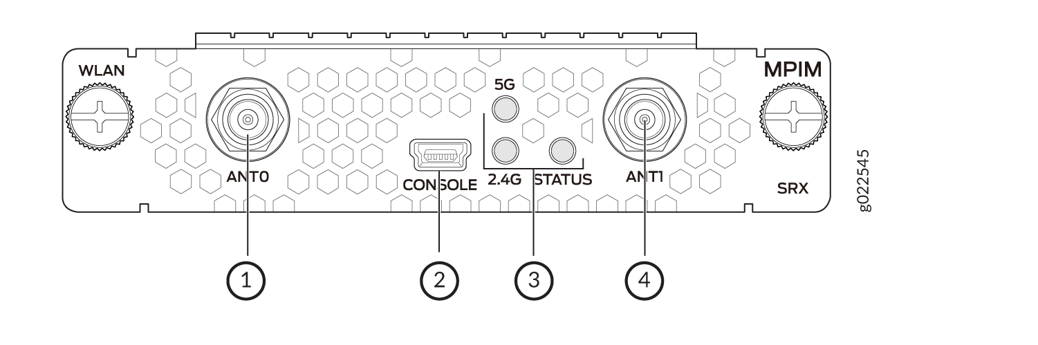
Table 1 lists the components on the front panel.
Sl. No. |
Component |
Description |
|---|---|---|
1, 4 |
Antenna connectors |
Two Reverse Polarity SubMiniature version A (RP-SMA) connectors |
2 |
Console |
Mini-USB Type-B port for debugging purposes |
3 |
LEDs |
Indicate the status of the Mini-PIM: 2.4 GHz
5 GHz
STATUS
|
Wi-Fi Mini-PIM Models
Three models are available based on the regional wireless standards (see Table 2):
Model or SKU |
Supported Region |
Notes |
|---|---|---|
SRX-MP-WLAN-US |
United States |
This model is based on the wireless standards supported in the United States. The country code is fixed and cannot be changed. |
SRX-MP-WLAN-IL |
Israel |
This model is based on the wireless standards supported in Israel. The country code is fixed and cannot be changed. |
SRX-MP-WLAN-WW |
Other countries |
You can set the country code using the For information on country codes, see Country Codes and Regulatory Domains |
Physical Interface
The physical interface for the Wi-Fi Mini-PIM uses the name wl-x/0/0, where x is the slot on the services gateway where the Mini-PIM is installed. You can install the Mini-PIM in any of the Mini-PIM slots on the services gateway.
Wi-Fi Mini-PIM Hardware Specifications
Table 3 provides the hardware specifications for the Mini-PIM.
Description |
Value |
|---|---|
Dimensions |
H x W x L: 0.79 in. x 3.70 in. x 5.29 in. (2.0 cm x 9.4 cm x 13.43 cm) |
Weight |
0.29 lb (0.13 kg) |
Form factor |
Mini-PIM |
Connector type |
RP-SMA |
Environmental operating temperature |
32° F through 104° F (0° C through 40° C) |
Storage temperature |
-40° F through 158° F (-40°C through 70° C) |
Relative humidity |
5% to 90% noncondensing |
Operating altitude |
6,000 feet (1828 meters) |
Antenna Specifications
The Mini-PIM supports two multi-band swivel-mount dipole antennas, which can be rotated 360 degrees. You can rotate the antennas and select the angle at which the signal strength is high. Table 4 lists the specifications for the antenna.
Specification |
Value |
|---|---|
Part number |
EDA-1713-25GR2-A3 (Vendor: MAG.LAYERS) |
Operating frequency range |
|
Impedance |
50 ohm |
Voltage standing wave ratio (VSWR) |
2 (maximum) |
Return loss |
10 dB (maximum) |
Radiation |
Omnidirectional |
Peak gain |
5dBi +/-0.5 |
Polarization |
Linear |
Operating temperature |
–4° F (–20° C) to 149° F (65° C) |
Connector type |
RP-SMA |
Channels and Frequencies Supported on the Wi-Fi Mini-PIM
The Wi-Fi Mini-PIM supports channel bandwidths of 20 MHz, 40
MHz, and 80 MHz. The 2.4 GHz radio supports 20 MHz and 40 MHz channel
bandwidths, and the 5 GHz radio supports 20 MHz, 40 MHz, and 80 MHz
channel bandwidths. You can configure the bandwidth by using the set wlan access-point ap-name radio [1|2] radio-option
channel bandwidth bandwidth command.
You can configure the 80 MHz channel bandwidth only on the 5 GHz radio.
The default channel bandwidth is 20 MHz for the 2.4 GHz radio and 40 MHz for the 5 GHz radio. Setting the bandwidth to 40 MHz or 80 MHz reduces the number of available channels for use.
Table 5 lists the channels supported on the 2.4 GHz radio.
Band |
Channel Number |
Center Frequency (MHz) |
|---|---|---|
2400~2483.5 MHz |
1 |
2412 |
2 |
2417 |
|
3 |
2422 |
|
4 |
2427 |
|
5 |
2432 |
|
6 |
2437 |
|
7 |
2442 |
|
8 |
2447 |
|
9 |
2452 |
|
10 |
2457 |
|
11 |
2462 |
|
12 |
2467 |
|
13 |
2472 |
Table 6 through Table 8 list the channels supported on the 5 GHz radio.
Band |
Channel Number |
Center Frequency MHz |
|---|---|---|
5150~5250 MHz |
36 |
5180 |
40 |
5200 |
|
44 |
5220 |
|
48 |
5240 |
|
5250~5350 MHz |
52 |
5260 |
56 |
5280 |
|
60 |
5300 |
|
64 |
5320 |
|
|
5470~5725 MHz |
100 |
5500 |
104 |
5520 |
|
108 |
5540 |
|
112 |
5560 |
|
116 |
5580 |
|
120 |
5600 |
|
124 |
5620 |
|
128 |
5640 |
|
132 |
5660 |
|
136 |
5680 |
|
140 |
5700 |
|
5725~5850 MHz |
144 | 5720 |
149 |
5745 |
|
153 |
5765 |
|
157 |
5785 |
|
161 |
5805 |
|
165 |
5825 |
Band |
Channel Number |
Center Frequency MHz |
|---|---|---|
5150~5250 MHz |
38 |
5190 |
46 |
5230 |
|
5250~5350 MHz |
54 |
5270 |
62 |
5310 |
|
5470~5725 MHz |
102 |
5510 |
110 |
5550 |
|
118 |
5590 |
|
126 |
5630 |
|
134 |
5670 |
|
142 |
5710 |
|
5725~5850 MHz |
||
151 |
5755 |
|
159 |
5795 |
Band |
Channel Number |
Center Frequency MHz |
|---|---|---|
5150~5250 MHz |
42 |
5210 |
5250~5350 MHz |
58 |
5290 |
5470~5725 MHz |
106 |
5530 |
122 |
5610 |
|
138 |
5690 |
|
5725~5850 MHz |
||
155 |
5775 |
Dynamic Frequency Selection
Dynamic Frequency Selection (DFS) enables use of 5 GHz frequencies that are typically reserved for radars. In countries where DFS is required, the Wi-Fi card performs appropriate checks for radar. If radar is detected on a channel, the access point selects a radar-free channel and performs a 60-second availability check before operating on that channel.
DFS is enabled by default. You can disable DFS by using the dfs-off option:
set wlan access-point ap-name radio
1 radio-options dfs-off
Only the 5 GHz radio (radio 1) supports DFS.
You can configure the DFS settings in any of the following ways based on your requirement:
DFS enabled (default)
If you set the
channel numbertoauto, the access point selects the channel from the list of DFS and non-DFS channels. If the access point selects a DFS channel and detects radar on the channel, it switches to another channel automatically.If you set the
channel numbermanually to a DFS channel and if the access point detects a radar on this channel, it switches to another channel automatically;
DFS disabled (dfs-off configured)
If you set the
channel numbertoauto, the access point selects the channel from the list of non-DFS channels.If you set the
channel numbermanually, you can configure either a DFS or non-DFS channel. If you configure a DFS channel with DFS disabled, a warning message appears when you commit the configuration.
Country Codes and Regulatory Domains
Table 9 lists the country codes and regulatory domains supported on the Wi-Fi Mini-PIM.
Country and Country Code |
Model |
Radio 1 (5 GHz) |
Radio 2 (2.4 GHz) |
|||||
|---|---|---|---|---|---|---|---|---|
Regulatory Domain (5 GHz) |
20 MHz |
40 MHz |
80 MHz |
Regulatory Domain (2.4 GHz) |
20 MHz |
40 MHz |
||
Australia (AU) |
SRX-MP-WLAN-WW |
FCC6 |
36, 40, 44, 48, 52, 56, 60, 64, 100, 104, 108, 112 116, 132, 136, 140, 144, 149, 153, 157, 161, 165 |
38, 46, 54, 62, 102, 110, 134, 142, 151, 159 |
42, 58, 106, 138, 155 |
WORLD |
1 to 13 |
1 to 13 |
Canada (CA) |
SRX-MP-WLAN-WW |
FCC6 |
36, 40, 44, 48, 52, 56, 60, 64, 100, 104, 108, 112 116, 132, 136, 140, 144, 149, 153, 157, 161, 165 |
38, 46, 54, 62, 102, 110, 134, 142, 151, 159 |
42, 58, 106, 138, 155 |
FCCA |
1 to 11 |
1 to 11 |
China (CN) |
SRX-MP-WLAN-WW |
APL14 |
36, 40, 44, 48, 52, 56, 60, 64, 149, 153, 157, 161, 165 |
38, 46, 54, 62, 151, 159 |
42, 58, 155 |
WORLD |
1 to 13 |
1 to 13 |
European Union |
SRX-MP-WLAN-WW |
ETSI11 |
36, 40, 44, 48, 52, 56, 60, 64, 100, 104, 108, 112, 116, 120, 124, 128, 132, 136, 140, 149, 153, 157, 161, 165 |
38, 46, 54, 62, 102, 110, 118, 126, 134 |
42, 58, 106, 122 |
WORLD |
1 to 13 |
1 to 13 |
India (IN) |
SRX-MP-WLAN-WW |
APL15 |
36, 40, 44, 48, 52, 56, 60, 64, 149, 153, 157, 161, 165 |
38, 46, 54, 62, 151, 159 |
42, 58, 155 |
WORLD |
1 to 13 |
1 to 13 |
Indonesia (ID) |
SRX-MP-WLAN-WW |
APL2 |
149, 153, 157, 161, 165 |
151, 159 |
155 |
ETSIC |
1 to 13 |
1 to 13 |
Israel (IL) |
SRX-MP-WLAN-IL |
ETSI3 |
36, 40, 44, 48, 52, 56, 60, 64 |
38, 46, 54, 62 |
42, 58 |
WORLD |
1 to 13 |
1 to 13 |
Japan (JP) |
SRX-MP-WLAN-WW |
MKK5 |
36, 40, 44, 48, 52, 56, 60, 64, 100, 104, 108, 112 116, 120, 124, 128, 132, 136, 140 |
38, 46, 54, 62, 102, 110, 118, 126, 134 |
42, 58, 106, 122 |
MKKC |
1 to 13 |
1 to 13 |
Malaysia (MY) |
SRX-MP-WLAN-WW |
FCC11 |
36, 40, 44, 48, 52, 56, 60, 64, 100, 104, 108, 112 116, 120, 124, 128, 149, 153, 157, 161, 165 |
38, 46, 54, 62, 102, 110, 118, 126, 151, 159 |
42, 58, 106, 122, 155 |
WORLD |
1 to 13 |
1 to 13 |
Mexico (MX) |
SRX-MP-WLAN-WW |
FCC3 |
36, 40, 44, 48, 52, 56, 60, 64, 100, 104, 108, 112 116, 120, 124, 128, 132, 136, 140, 144, 149, 153, 157, 161, 165 |
38, 46, 54, 62, 102, 110, 118, 126, 134, 142, 151, 159 |
42, 58, 106, 122, 138, 155 |
ETSIC |
1 to 13 |
1 to 13 |
New Zealand (NZ) |
SRX-MP-WLAN-WW |
FCC3 |
36, 40, 44, 48, 52, 56, 60, 64, 100, 104, 108, 112 116, 120, 124, 128, 132, 136, 140, 144, 149, 153, 157, 161, 165 |
38, 46, 54, 62, 102, 110, 118, 126, 134, 142, 151, 159 |
42, 58, 106, 122, 138, 155 |
ETSIC |
1 to 13 |
1 to 13 |
South Korea (KR) |
SRX-MP-WLAN-WW |
APL9 |
36, 40, 44, 48, 52, 56, 60, 64, 100, 104, 108, 112 116, 120, 124, 128, 132, 136, 140, 149, 153, 157, 161, 165 |
38, 46, 54, 62, 102, 110, 118, 126, 134, 151, 159 |
42, 58, 106, 122, 155 |
WORLD |
1 to 13 |
1 to 13 |
United States (US) |
SRX-MP-WLAN-US |
FCC8 |
36, 40, 44, 48, 52, 56, 60, 64, 100, 104, 108, 112, 116, 120, 124, 128, 132, 136, 140, 144, 149, 153, 157, 161, 165 |
38, 46, 54, 62, 102, 110, 118, 126, 134, 142, 151, 159 |
42, 58, 106, 122, 138, 155 |
FCCA |
1 to 11 |
1 to 11 |
Vietnam (VN) |
SRX-MP-WLAN-WW |
FCC3 |
36, 40, 44, 48, 52, 56, 60, 64, 100, 104, 108, 112 116, 120, 124, 128, 132, 136, 140, 144, 149, 153, 157, 161, 165 |
38, 46, 54, 62, 102, 110, 118, 126, 134, 142, 151, 159 |
42, 58, 106, 122, 138, 155 |
WORLD |
1 to 13 |
1 to 13 |
RF Specifications for the Wi-Fi Mini-PIM
Table 10 lists the radio frequency (RF) specifications.
Operating Mode |
Data Rate |
Receive Sensitivity (+/-2 dBm) Per Chain |
Target Power (+/-2 dBm) Per Chain |
|---|---|---|---|
802.11ac (VHT20) |
MCS0 |
-88 |
16.5 |
MCS8 |
-67 |
11.5 |
|
802.11ac (VHT40) |
MCS0 |
-87 |
16 |
MCS9 |
-64 |
11 |
|
802.11ac (VHT80) |
MCS0 |
-83 |
15.5 |
MCS9 |
-59 |
10.5 |
|
802.11a |
6 Mbps |
-88 |
16.5 |
54 Mbps |
-72 |
13 |
|
802.11b |
1 Mbps |
-94 |
18 |
11 Mbps |
-85 |
18 |
|
802.11g |
6 Mbps |
-89 |
18 |
54 Mbps |
-71 |
15 |
|
802.11n (HT20) 2G |
MCS0 |
-88 |
18 |
MCS7 |
-70 |
15 |
|
802.11n (HT20) 5G |
MCS0 |
-88 |
16.5 |
MCS7 |
-71 |
13 |
|
802.11n (HT40) 2G |
MCS0 |
-86 |
17 |
MCS7 |
-68 |
15 |
|
802.11n (HT40) 5G |
MCS0 |
-86 |
16 |
MCS7 |
-69 |
12 |
Installing the Wi-Fi Mini-PIM in an SRX Series Services Gateway
You can install the Mini-PIM in any of the Mini-PIM slots on the services gateway.
You can install only one Wi-Fi Mini-PIM in a services gateway.
To install the Mini-PIM in a services gateway:
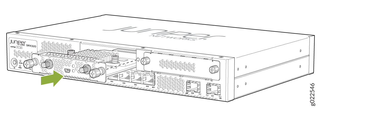
- Slide the Mini-PIM in the slot until it lodges firmly
in the services gateway. Tighten the screws on each side of the Mini-PIM
faceplate. See Figure 2.Figure 2: Installing the Wi-Fi Mini-PIM
- Attach the antennas to the front panel of the Mini-PIM.
You can attach the antenna by using one of the following methods:
Direct mounting—Attach the antennas to the RP-SMA connectors on the front panel (see Figure 3).
Figure 3: Attaching the Antennas (Direct Mounting)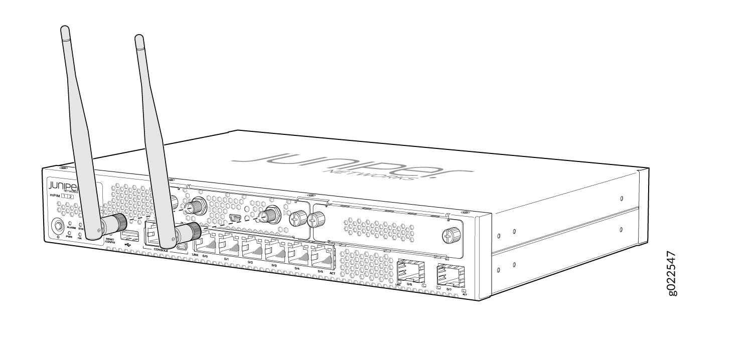
Using an external antenna base—Attach the antennas to the antenna base. Connect the cables from each antenna base to the RP-SMA connectors on the front panel (see Figure 4).
Figure 4: Attaching the Antennas Using an Antenna Base (Rack Mounting)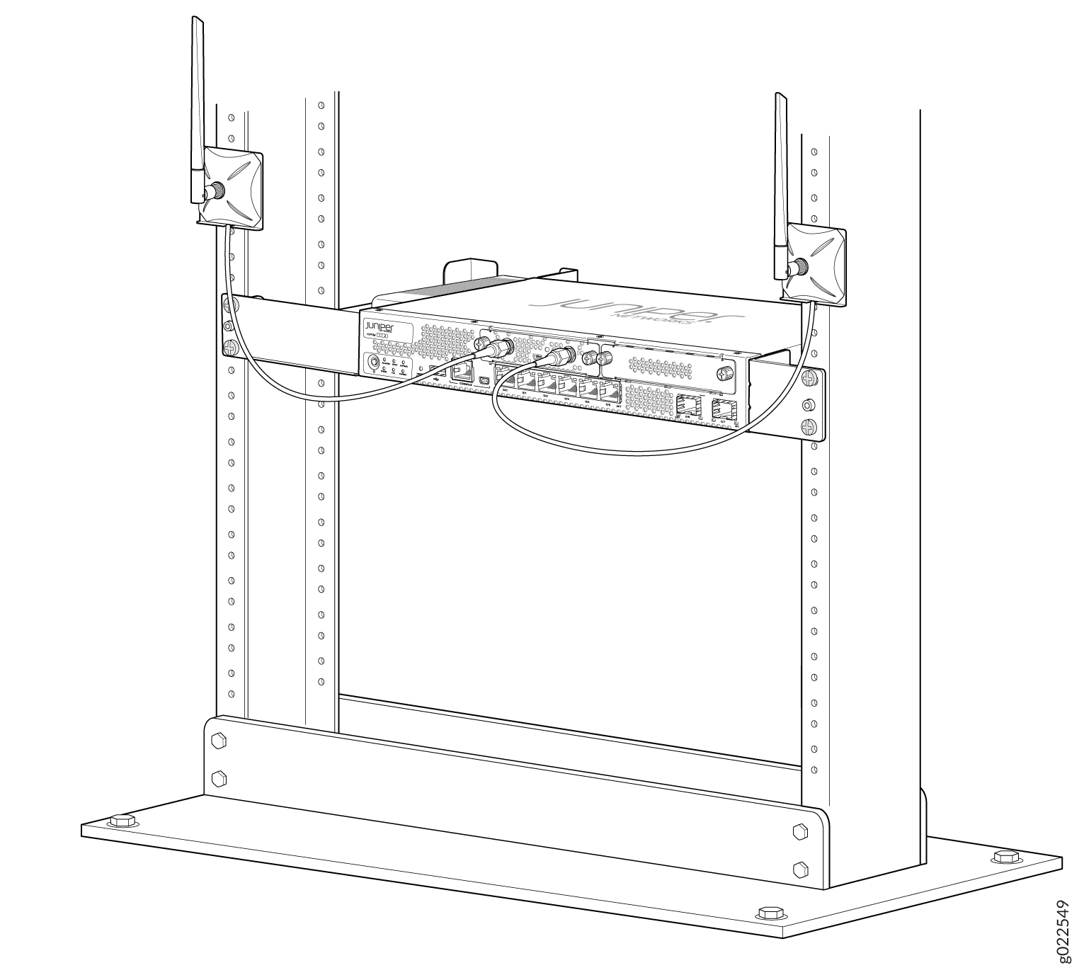
For SRX320 Services Gateways, which can be mounted on a wall, you can mount the antennas on a wall as shown in Figure 5.
Figure 5: Attaching the Antennas Using an Antenna Base (Wall Mounting)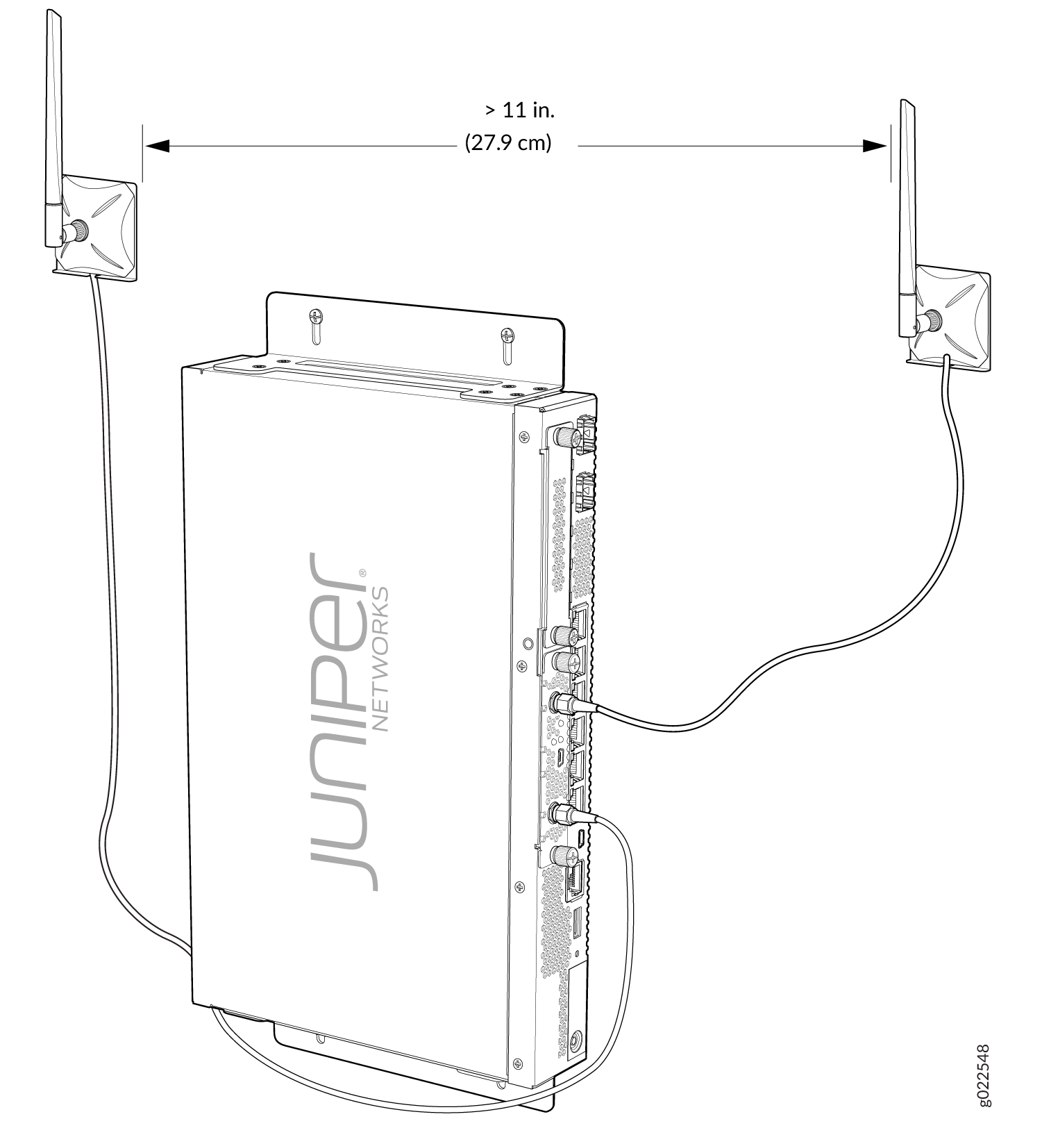
Configuring the Wi-Fi Mini-PIM on an SRX Series Services Gateway
- Wi-Fi Mini-PIM Configuration Overview
- Radio Configuration Overview
- Virtual Access Point Configuration Overview
- Configure the Wi-Fi Mini-PIM
Wi-Fi Mini-PIM Configuration Overview
Before you configure the Mini-PIM, configure the network settings on the SRX Series Firewall and connect the device to your network. For details, see the Hardware Guide for your SRX Series Firewall.
Configure the following settings for the access point:
Name for the access point
Interface—The interface name for the AP is denoted as wl-x/0/0, where x is the slot on the services gateway in which the Mini-PIM is installed.
Country code—The country code setting identifies the regulatory domain in which the access point operates.
The country code affects the radio modes, list of channels, and radio transmission power that the access point can support. Ensure that you select the correct code for the country in which the access point operates so that the access point complies with the regulations in that country.
Location
Radio Configuration Overview
Radios on the Wi-Fi Mini-PIM are enabled by default. You can disable a radio. When a radio is disabled, the Mini-PIM does not send messages to the connected wireless clients.
Configure the following options for each radio:
Channel number—If you select
auto, then the Mini-PIM chooses the channel automatically.Mode—You can configure the radio to support either one type of wireless client or a mixed mode. In mixed mode, different types of clients can connect to the radio. Table 11 lists the modes supported on each radio.
Table 11: Supported Modes on the Wi-Fi Mini-PIM radios Radio
Supported Modes
Radio 1 (5.0 GHz)
an—802.11a and 802.11n clients operating on 5 GHz frequency can connect to the access point
acn—802.11a, 802.11n and 802.11ac clients operating on 5 GHz frequency can connect to the access point
Radio 2 (2.4 GHz)
gn—802.11g, and 802.11n clients operating in 2.4 GHz frequency can connect to the access point. This is the default mode for this radio.
g (supported from Junos OS Release 20.4R1)—802.11g clients operating in 2.4 GHz frequency can connect to the access point.
Bandwidth—Radio 1 supports 20 MHz, 40 MHz, and 80 MHz bandwidths, whereas Radio 2 supports only 20 MHz and 40 MHz bandwidths.
Transmit power—You can configure transmit power on a per-radio basis. By default, the access point assigns 100 percent power to each radio at startup.
To increase the network capacity, place access points closer together and reduce the value of the transmit power. This helps reduce overlap and interference among access points. A lower transmit power setting can also keep your network more secure because weaker wireless signals are less likely to propagate outside the physical location of your network.
Virtual Access Point Configuration Overview
Virtual access points (VAPs) allow different security mechanisms for different clients on the same access point. Each VAP is identified by a configured service set identifier (SSID) and a unique basic service set identifier (BSSID). The access point supports multiple VLANs, which can be distributed across VAPs and radios.
You can enable or disable each VAP independently. If you do
not configure the VAPs, the radio is turned on if you configured the
radio settings. The radio is off if you do not configure the radio
settings or if you turned off the radio using the radio-off option.
A VAP is configured on a per-radio basis. You can configure up to eight VAPs per radio. You can map up to 16 ESSIDS to individual VLANs.
Configure the following options for each VAP:
Description (maximum length is 64)
SSID value for the VAP
The SSID value can include letters, numerals, and the special characters - . _ @ #. The minimum length is 2 characters and maximum length is 32 characters.
VLAN ID for the VAP
The value can be in the range of 1 through 4094.
The maximum number of clients that can connect to the VAP
The value can be in the range of 1 through 127.
Security for the access point
The access point supports several types of authentication methods that are used by clients to connect to the access point. Each of these methods and their associated parameters are configurable on a per-VAP basis. By default, no security is in place on the access point, and therefore any wireless client can associate with it and access your LAN. You configure secure wireless client access for each VAP.
None—The data transferred between clients and the access point is not encrypted. This method allows clients to associate with the access point without any authentication.
Wi-Fi Protected Access (WPA) Enterprise—A Wi-Fi Alliance standard that uses RADIUS server authentication with AES-CCMP cipher suite. This mode allows the use of high security encryption along with centrally managed user authentication. Only the WPA2 standard is supported.
Wi-Fi Protected Access (WPA) Personal—A Wi-Fi Alliance standard that uses preshared key (PSK) authentication with AES-CCMP cipher suite. Only the WPA2 standard is supported.
Configure the Wi-Fi Mini-PIM
To configure the Wi-Fi Mini-PIM:
Verify the Status of the Wi-Fi Mini-PIM
Table 12 lists the commands that you can use to verify and monitor the status of the Wi-Fi Mini-PIM:
Command |
Purpose |
|---|---|
|
Displays the status of the specific access point. Sample output:
Active access point detail information

Access Point          : wap3
Type                  : Internal
Location              : Default Location
Serial Number         : EV1119AF0030
Firmware Version      : v1.2.7
Alternate Version     : v1.1.0
Country               : US
Access Interface      : wl-2/0/0
System Time           : Mon Dec 23 06:50:50 UTC 2019
Packet Capture        : Off
Ethernet Port:
    MAC Address       : 00:00:5e:00:53:c0
Radio1:
    Status            : On
    MAC Address       : 00:00:5e:00:53:12
    Temperature       : 44
    Mode              : IEEE 802.11a/n/ac
    Channel           : 120
    Bandwidth         : 40
    Transmit Power    : 100
Radio2:
    Status            : On
    MAC Address       : 00:00:5e:00:53:56
    Temperature       : 45
    Mode              : IEEE 802.11g/n
    Channel           : 11
    Bandwidth         : 20
    Transmit Power    : 100
|
|
Displays the details of all the access points configured on the Mini-PIM. Sample: Active access points information Access-Point Type Interface Radio-mode/Channel/Bandwidth wap3 Int wl-2/0/0 acn/120/40, gn/11/20 |
|
Displays the details about the clients connected to the access point. Access point client associations information Access point: wap3 VAP Client MAC Address Auth Packets Rx/Tx Bytes Rx/Tx Radio1:5g_vap1 00:00:5e:00:53:a3 NO 3/0 510/0 |
|
Displays details about the virtual access points. Virtual access points information
Access point name: wap3
Radio1:
VAP1:
SSID : 5g_vap1
MAC Address : 00:00:5e:00:53:12
Maximum Station : 127
Broadcast SSID : Enable
Station Isolation : Disable
Upload Limit : Disable
Download Limit : Disable
VLAN ID : 0
Station MAC Filter : Disable
Traffic Statistics:
Input Bytes : 0
Output Bytes : 0
Input Packets : 0
Output Packets : 0
VAP2:
SSID : 5g_vap2
MAC Address : 00:00:5e:00:53:12
Maximum Station : 100
Broadcast SSID : Enable
Station Isolation : Disable
Upload Limit : Disable
Download Limit : Disable
VLAN ID : 0
Station MAC Filter : Disable
Traffic Statistics:
Input Bytes : 0
Output Bytes : 0
Input Packets : 0
Output Packets : 0
Radio2:
VAP0:
SSID : 2.4g
MAC Address : 00:00:5e:00:53:56
Maximum Station : 127
Broadcast SSID : Enable
Station Isolation : Disable
Upload Limit : Disable
Download Limit : Disable
VLAN ID : 0
Station MAC Filter : Disable
Traffic Statistics:
Input Bytes : 10802142
Output Bytes : 6228524
Input Packets : 100266
Output Packets : 36413
|
Upgrading the Firmware on the Wi-Fi Mini-PIM
To upgrade the firmware on the Mini-PIM using the CLI: