
Maintain the QFX5241-32OD-DO-T1 Power System
The Power supply units (PSUs) in the QFX5241-32OD-DO-T1 switch are hot-removable and hot-insertable Field-Replaceable Units (FRUs), allowing them to be removed and installed without powering down the switch or disrupting normal switching operations. PSUs can also be replaced when the switch is powered off and off-rack.
The ORv3-compliant QFX5241-32OD-DO-T1 switches support the replacement of field replaceable units (FRU) such as PSUs. For more information on the PSUs, power requirements, and redundancy support, see QFX5241-32OD Power System. The PSUs can be replaced at the following operational states:
- On rack (fully installed)—You can replace the PSU while the switch is installed on the ORv3 rack. The switch-tray assembly is powered by the busbar in this state and fully operational.
- Off rack, on tray—You can replace the PSU after the switch is removed from the ORv3 rack, but still attached to the tray. The switch is not operational in this state.
Remove a Power Supply Unit from QFX5241-32OD-DO-T1 Switch While Operational
We ship QFX5241-32OD-DO-T1, the ORv3-compliant variant of the switch, from the factory with two DC power supply units (PSUs).
Before you remove a PSU from the QFX5241-32OD-DO-T1 switch, ensure that you have taken the necessary precautions to prevent electrostatic discharge (ESD) damage.
Ensure that you have the following parts and tools available to remove a PSU from a QFX5241-32OD-DO-T1 switch:
-
ESD grounding strap
-
Antistatic bag or an antistatic mat
To remove a PSU from the QFX5241-32OD-DO-T1 switch:
-
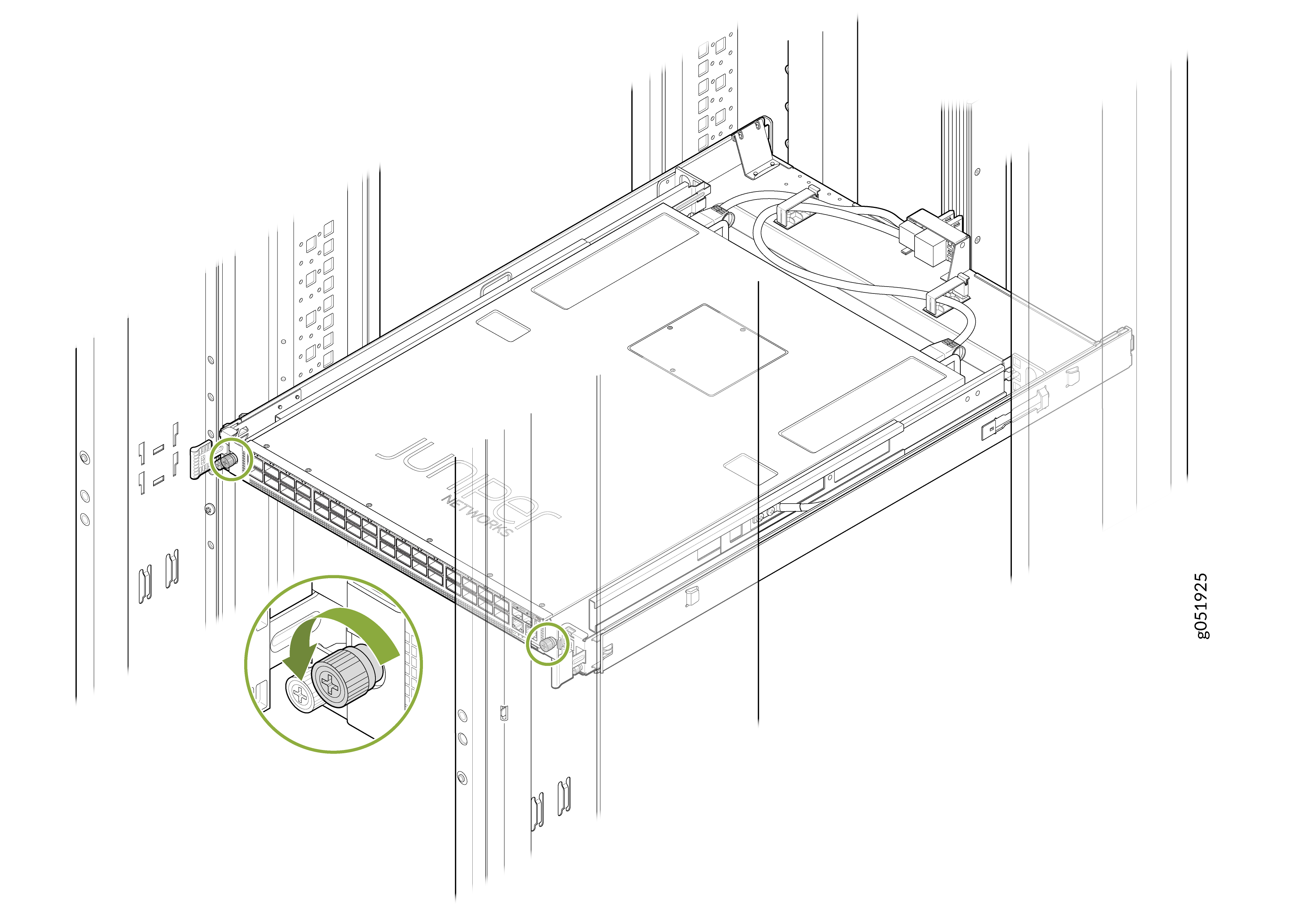
Loosen and remove the thumbscrews on both sides of the chassis to unfasten
the switch from the switch-tray assembly.
Figure 1: Remove the Thumbscrews
-
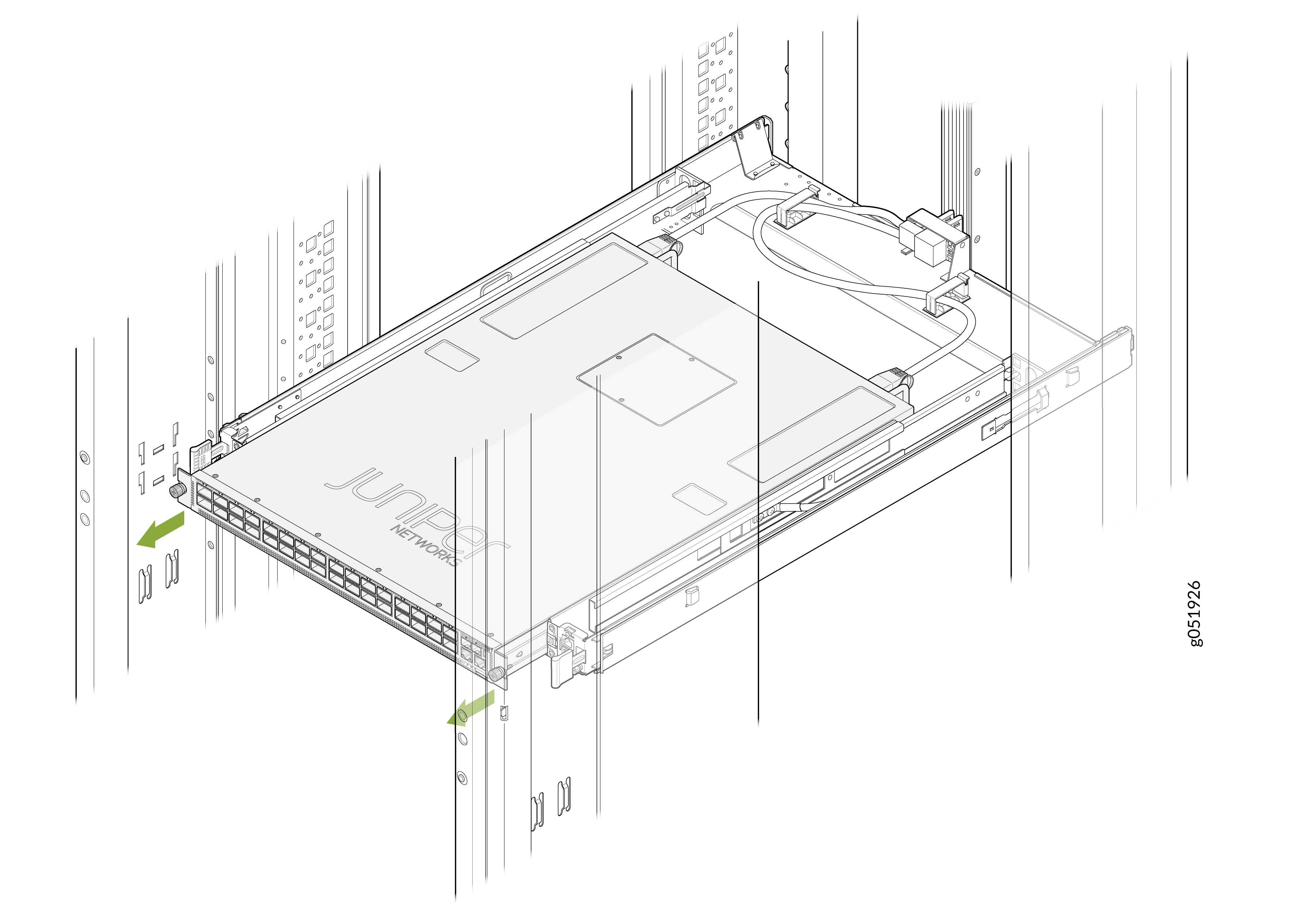
Slide the switch chassis toward the front until the PSU module is
accessible.
Note: You must slide the chassis to the front in the switch-tray assembly by approximately 150 mm to ensure that the PSUs are accessible.Figure 2: Slide the Switch
-
Remove the power cord from the PSU faceplate.
Gently pull the circular grip on the pull-tab latch of the DC power cord to release the lock on the DC PSU faceplate. Once the lock is released, pull the power cord to detach it from the PSU faceplate.
CAUTION:Do not pull the circular grip on the pull-tab latch and the DC PSU power cord simultaneously.Figure 3: Remove the DC PSU Power Cord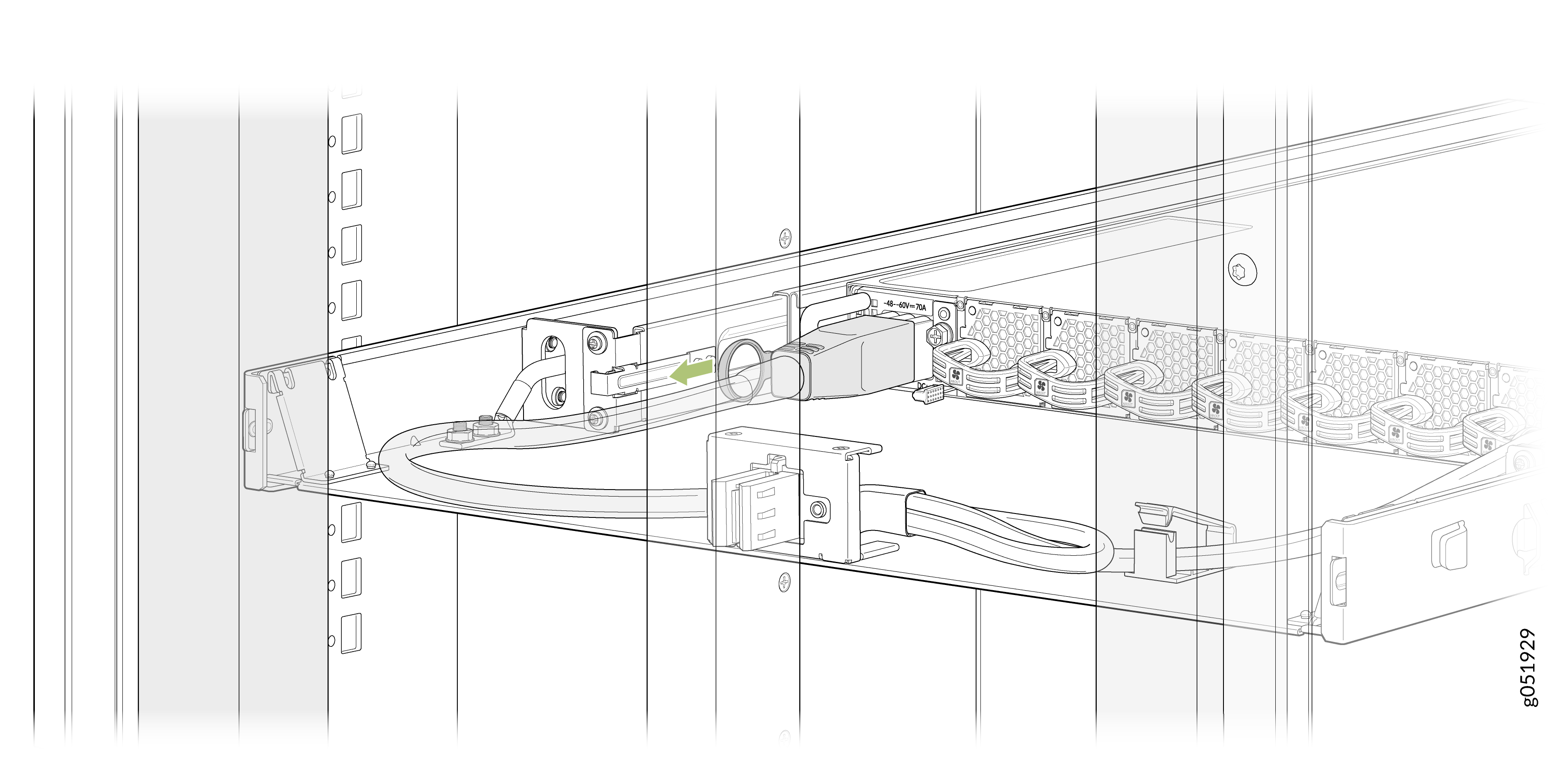
-
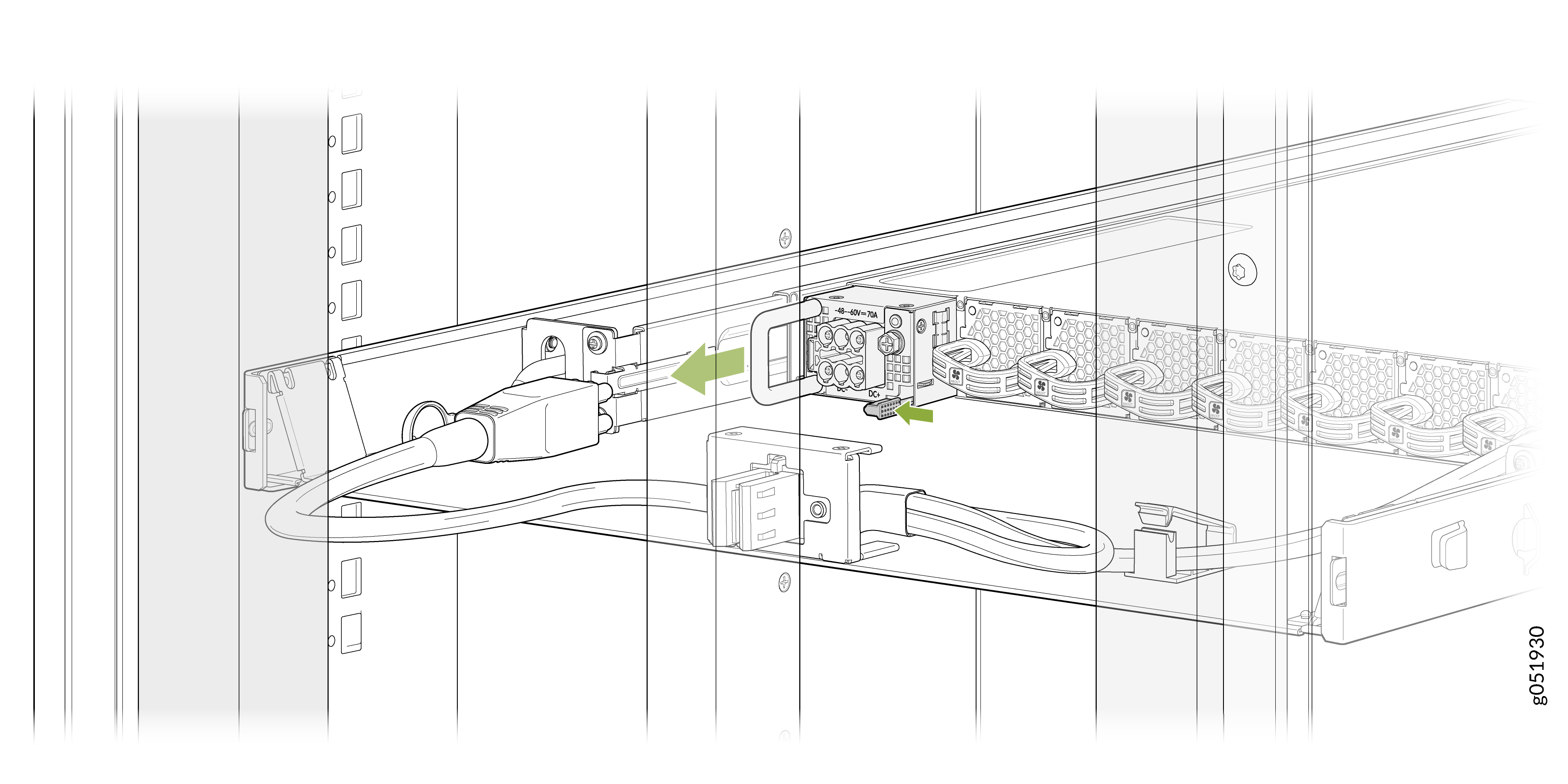
Grasp the PSU handle and pull firmly to slide the PSU halfway out of the
chassis.
Figure 4: Remove the DC PSU from QFX5241-32OD-DO-T1 Switch
Remove a Power Supply Unit from QFX5241-32OD-DO-T1 Switch While Off-Rack
We ship QFX5241-32OD-DO-T1, the ORv3-compliant variant of the switch, from the factory with two DC power supply units (PSUs).
Before you remove a PSU from the QFX5241-32OD-DO-T1 switch, ensure that you have taken the necessary precautions to prevent electrostatic discharge (ESD) damage.
Ensure that you have the following parts and tools available to remove a PSU from a QFX5241-32OD-DO-T1 switch:
-
ESD grounding strap
-
Antistatic bag or an antistatic mat
To remove a PSU from the QFX5241-32OD-DO-T1 switch:
-
Remove the power cord from the PSU faceplate.
Gently pull the circular grip on the pull-tab latch of the DC power cord to release the lock on the DC PSU faceplate. Once the lock is released, pull the power cord to detach it from the PSU faceplate.
CAUTION:Do not pull the circular grip on the pull-tab latch and the DC PSU power cord simultaneously.Figure 5: Remove the DC PSU Power Cord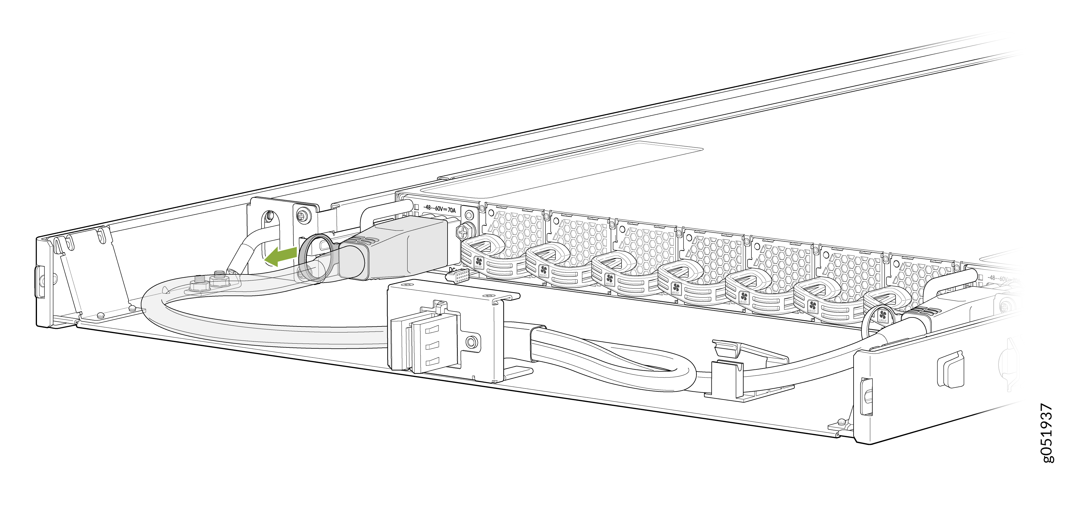
-
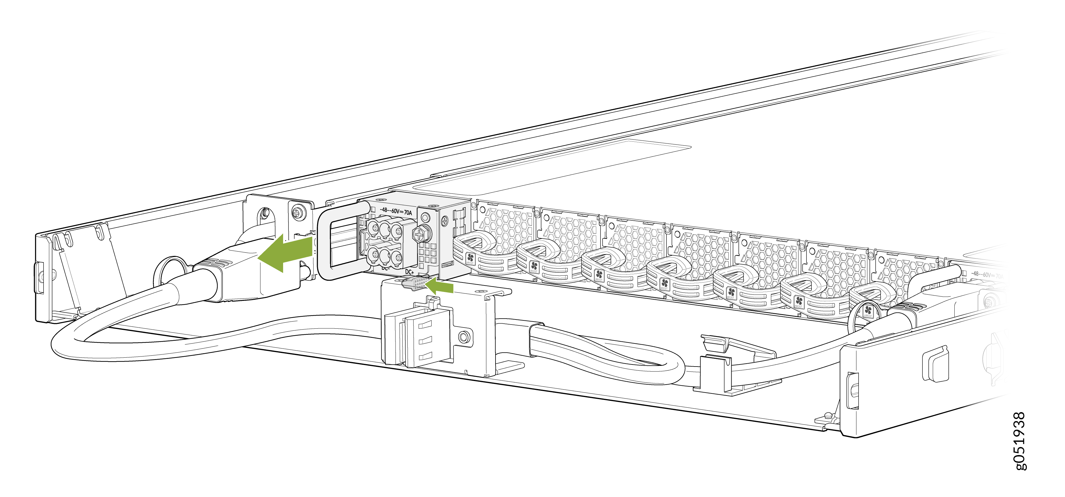
Grasp the PSU handle and pull firmly to slide the PSU halfway out of the
chassis.
Figure 6: Remove the DC PSU from QFX5241-32OD-DO-T1 Switch
Install a Power Supply Unit in QFX5241-32OD-DO-T1 Switch While Operational
-
Before you install a DC PSU in the QFX5241-32OD-DO-T1 switch, ensure that you have taken the necessary precautions to prevent electrostatic discharge (ESD) damage.
-
Ensure that the airflow direction of the PSU is the same as the chassis. Labels on the PSU handle indicate the direction of airflow. See QFX5241-32OD Cooling System for more information.
To install a PSU in the QFX5241-32OD-DO-T1 switch:
-
Loosen and remove the thumbscrew on both sides of the chassis to unfasten
the switch from the switch-tray assembly.
Figure 7: Remove the Thumbscrews
-
Slide the switch chassis toward the front until the PSU module is
accessible.
Note: You must slide the chassis to the front in the switch-tray assembly by approximately 150 mm to ensure that the PSUs are accessible.Figure 8: Slide the Switch
-
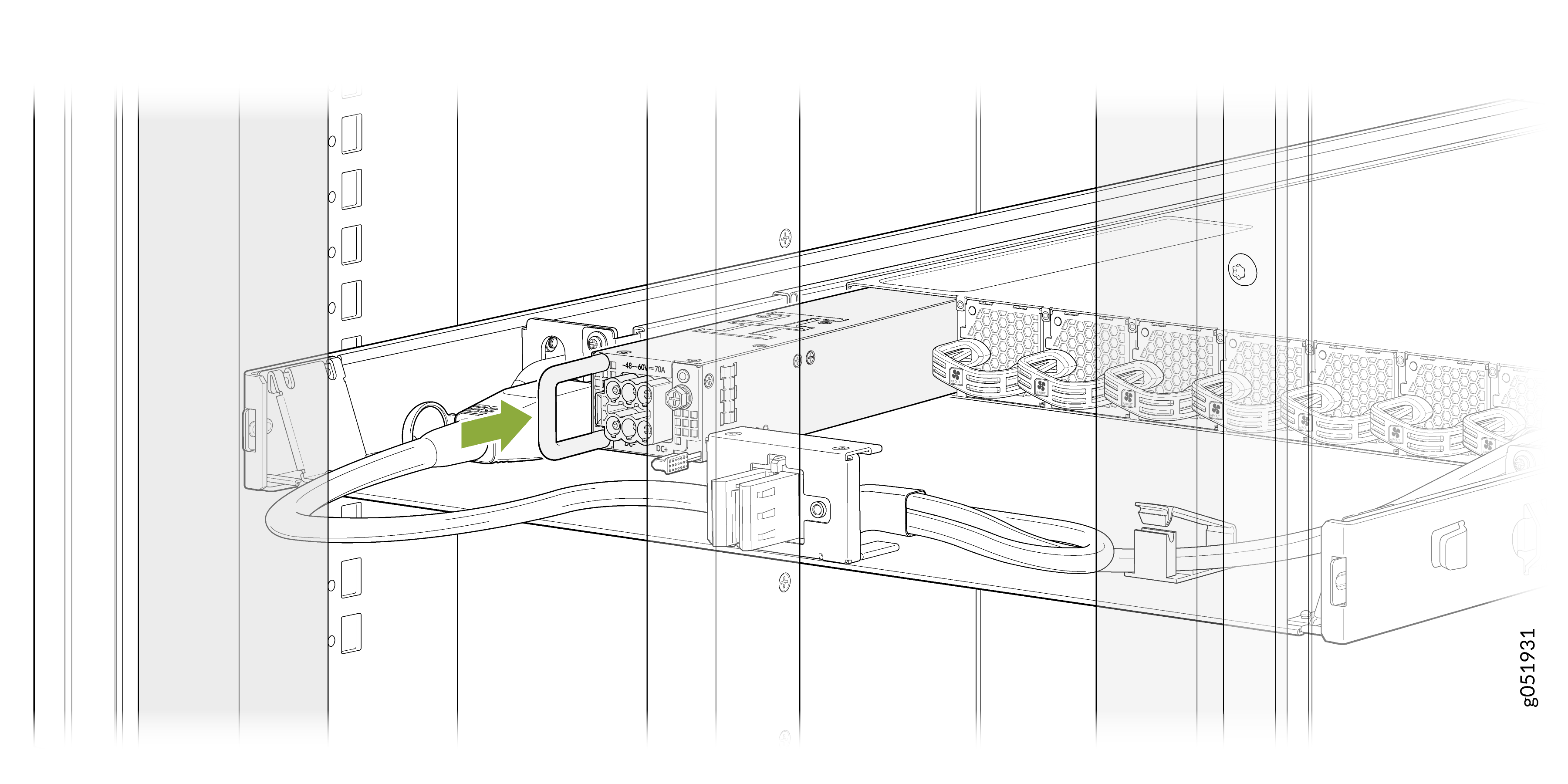
Using both hands, place the PSU in the PSU slot on the FRU panel of the
switch and slide it in until it is fully seated.
Figure 9: Install the DC PSU in the Operational Switch
-
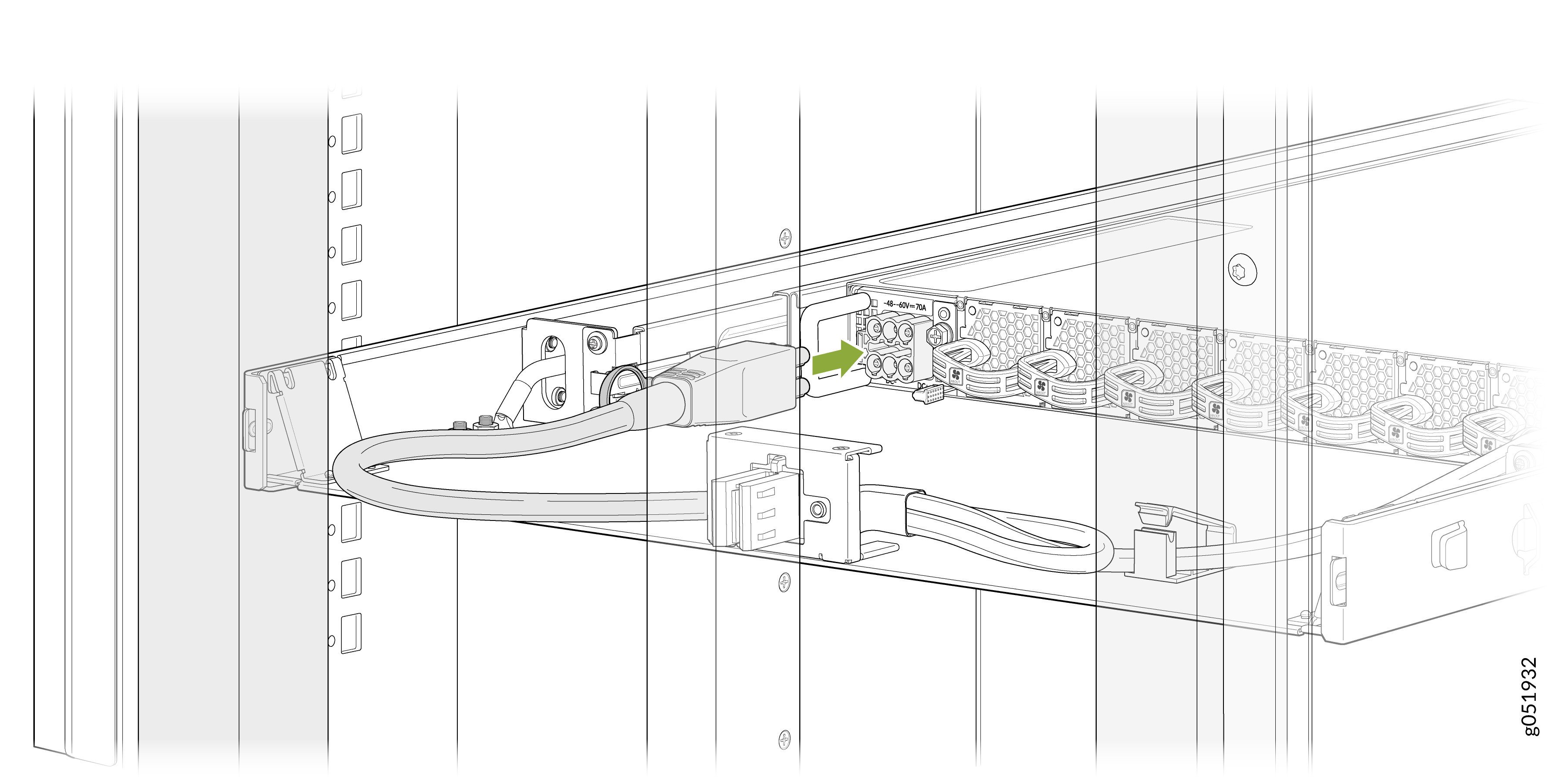
Connect the DC power cord.
Figure 10: Connect the DC Power Cord
-
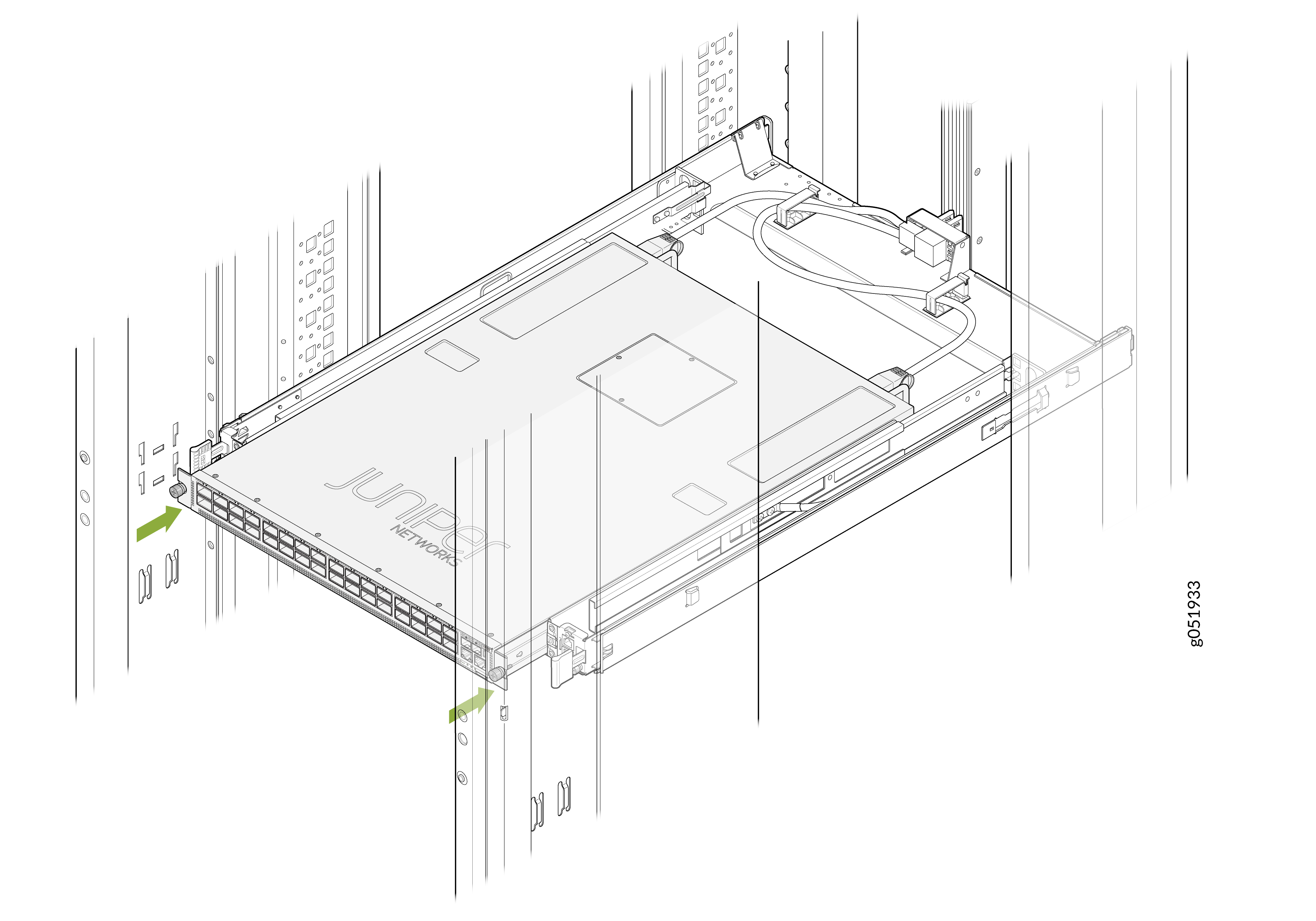
Slide the switch-tray assembly back into place.
Figure 11: Slide the Switch-Tray into Position
-
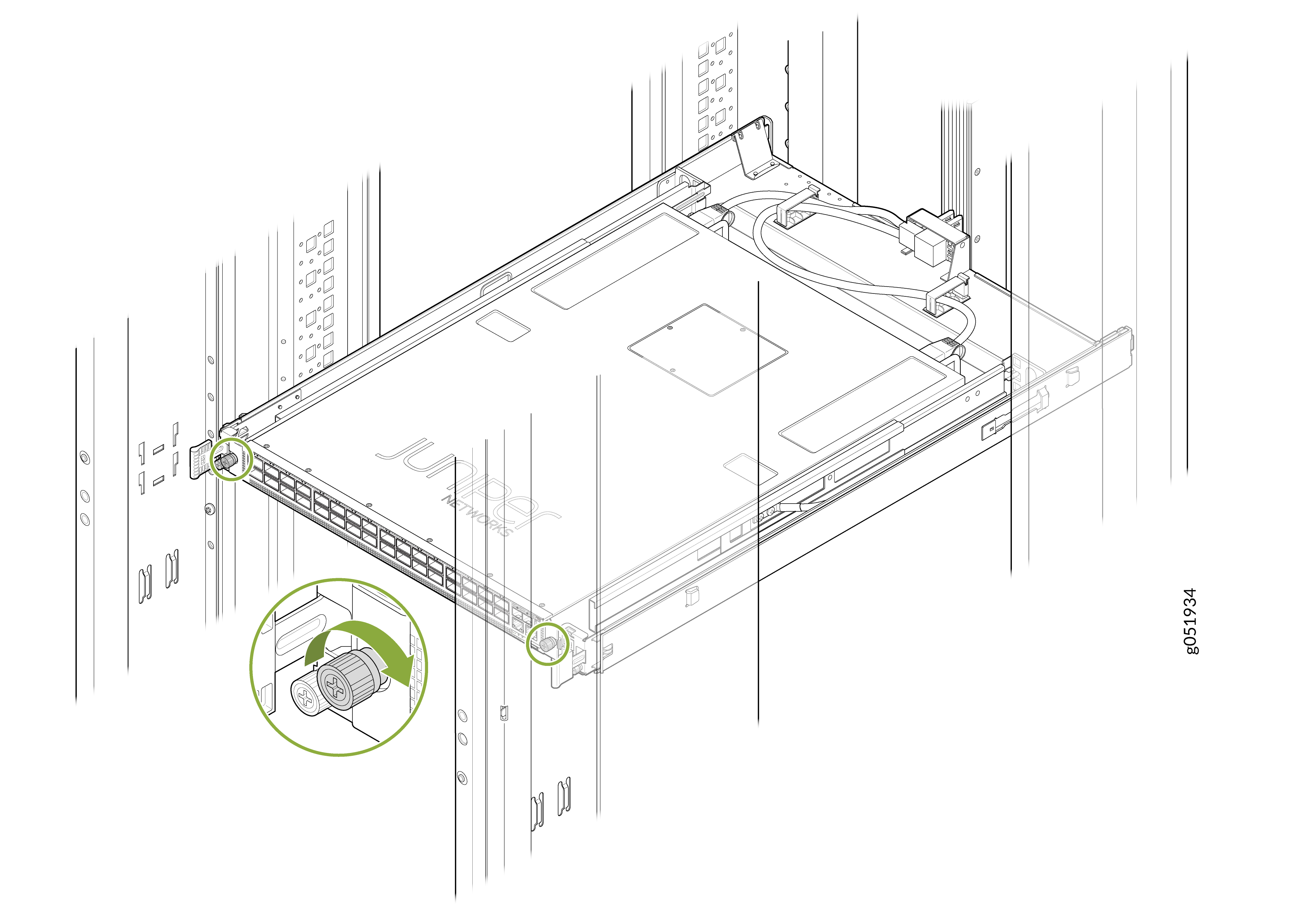
Tighten the thumbscrews on both sides of the chassis.
Figure 12: Tighten the Thumbscrews
If you have a Juniper Care service contract, register any addition, change, or upgrade of hardware components at https://www.juniper.net/customers/support/tools/updateinstallbase/. Failure to do so can result in significant delays if you need replacement parts. This note does not apply if you replace existing components with the same type of component.
Install a Power Supply Unit in QFX5241-32OD-DO-T1 While Off-Rack
-
Before you install a DC PSU in the QFX5241-32OD-DO-T1 switch, ensure that you have taken the necessary precautions to prevent electrostatic discharge (ESD) damage.
-
Ensure that the airflow direction of the PSU is the same as the chassis. Labels on the PSU handle indicate the direction of airflow. See QFX5241-32OD Cooling System for more information.
To install a PSU in the QFX5241-32OD-DO-T1 switch:
-
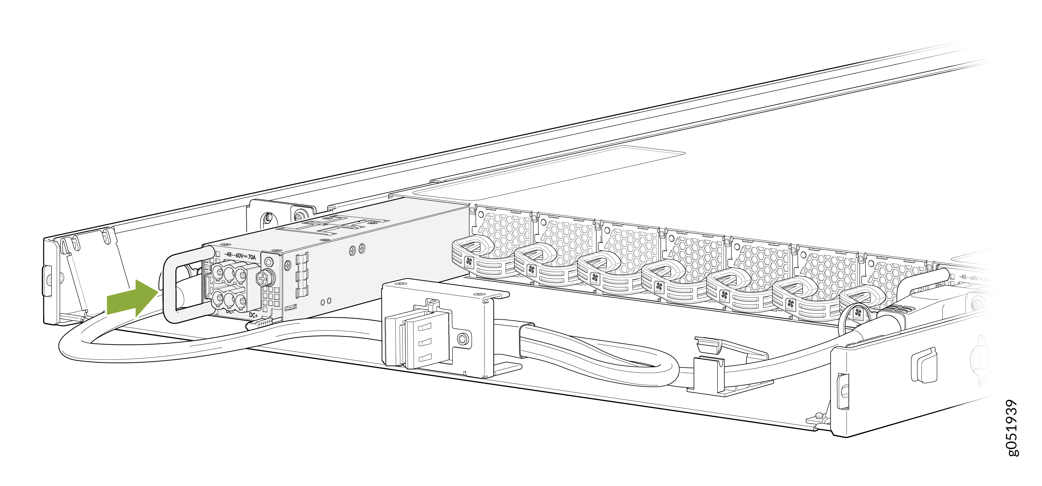
Using both hands, place the PSU in the PSU slot on the FRU panel of the
switch and slide it in until it is fully seated.
Figure 13: Install the DC PSU in Off-Rack Switch
-
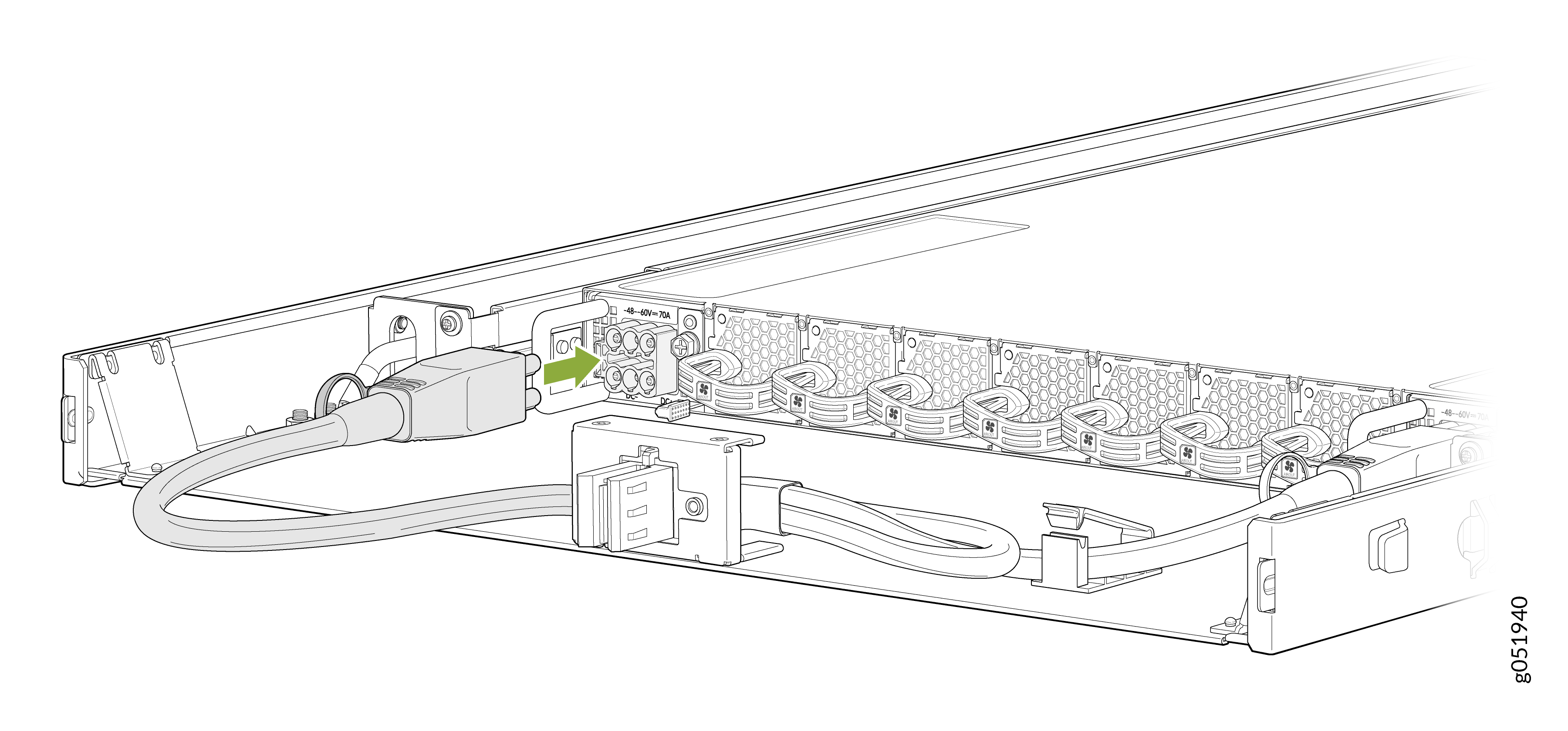
Connect the DC power cord.
Figure 14: Connect the DC Power Cord
If you have a Juniper Care service contract, register any addition, change, or upgrade of hardware components at https://www.juniper.net/customers/support/tools/updateinstallbase/. Failure to do so can result in significant delays if you need replacement parts. This note does not apply if you replace existing components with the same type of component.