QFX5241-32OD Cooling System
QFX5241-32OD Cooling System Description
The components of the cooling system work together to keep the switch within the acceptable temperature range. The cooling system consists of the following components:
During normal operation, the fans in the fan module operate at moderate or less than full speed. If a fan fails or the ambient temperature rises above a threshold, the cooling system of the switch automatically adjusts the speed of the remaining fans. This speed adjustment helps to keep the temperature within the acceptable range. If the maximum temperature specification is exceeded and the system cannot be adequately cooled, the switch shuts down some or all of the hardware components.
Fan Modules
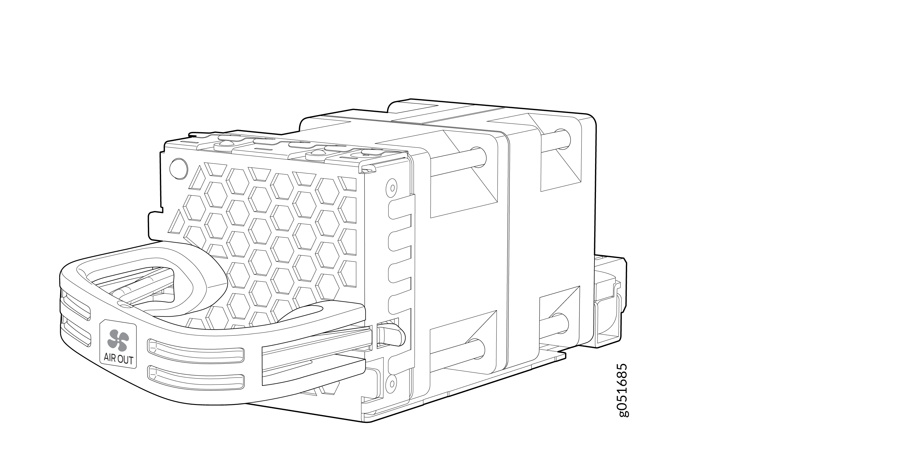
The QFX5241-32OD have seven hot-insertable and hot-removable field-replaceable fan modules (QFX5241-1U-FAN-O) installed at the rear of the switch. Each fan tray module houses two 40 mm x 56 mm counter-rotating rotors. The cooling system offers N+1 redundancy at the rotor level.
You can remove and replace a fan module from the FRU end of the chassis. When you replace a fan when the switch is running, the switch continues to operate for a limited period of time (2 minutes) without thermal alarms or shutdown.
The fan modules in the QFX5241-32OD are FRUs designed for port-to-FRU airflow, which is also known as AFO or front-to-back airflow. The fan modules are numbered from 0 through 6. Each fan module is 1-U high and has an associated LED to indicate its status.
The fan speed varies based on the temperature of internal components, optics modules, and the ambient temperature. The maximum speed at which fans operate depends on the ambient temperature that you have set. As the fan speed increases, the power consumed by the fans increases. As a result, the device consumes more power when the temperature is high because the fans run faster to maintain the operating temperature of the chassis within the configured limits.
The QFX5241-32OD switch must operate with all the seven fan modules installed. If you need to replace a faulty fan module, see QFX5241-32OD Fan Module Status LED.
QFX5241-32OD Fan Module Status LED
Each fan module has one bicolor status LED.
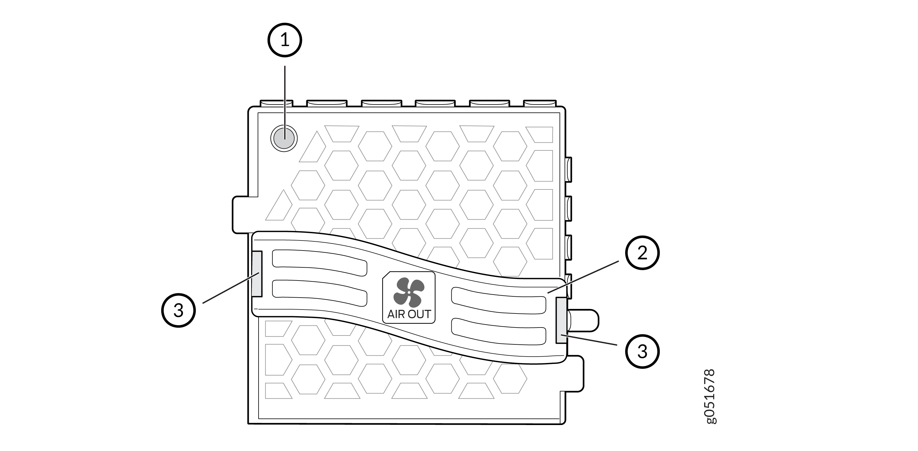
1 — Fan module LED | 3 — Lock release handle |
2 — Handle |
Table 1 describes the behavior of the fan module status LED.
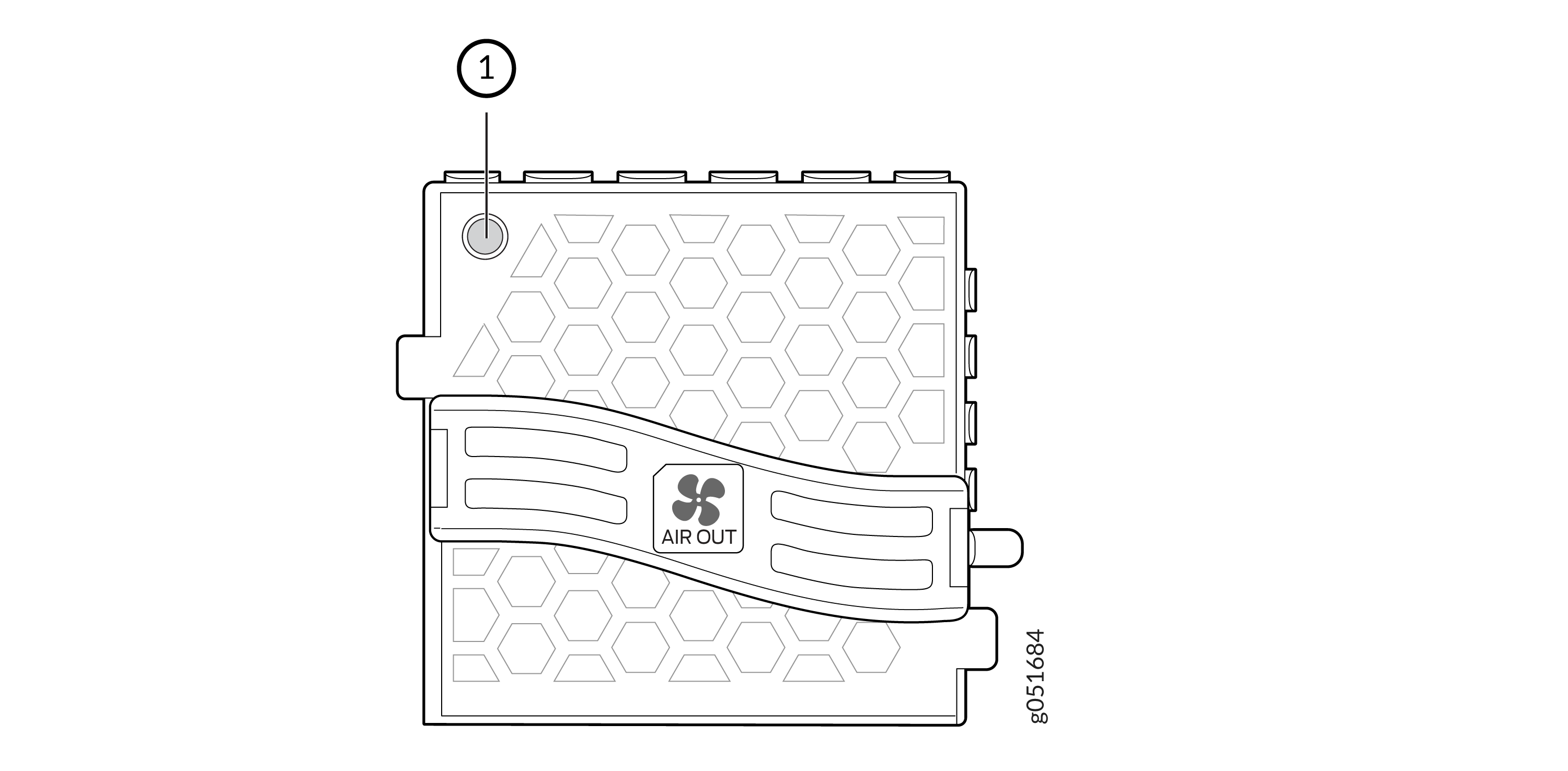
1 — Fan module status LED |
|
Color |
State |
Description |
|---|---|---|
|
Green |
On steadily |
Fan module is functioning normally. |
|
Red |
On steadily |
Fan module is faulty and malfunctioning. |
|
Unlit |
Off |
Fan module experiences input power failure. |
Under normal operating conditions, the fan modules operate at a moderate speed. Temperature sensors in the chassis monitor the temperature within the chassis.
The system raises an alarm if a fan module fails or if the ambient temperature inside the chassis rises above the acceptable range. If the temperature inside the chassis rises above the threshold temperature, the system shuts down automatically.
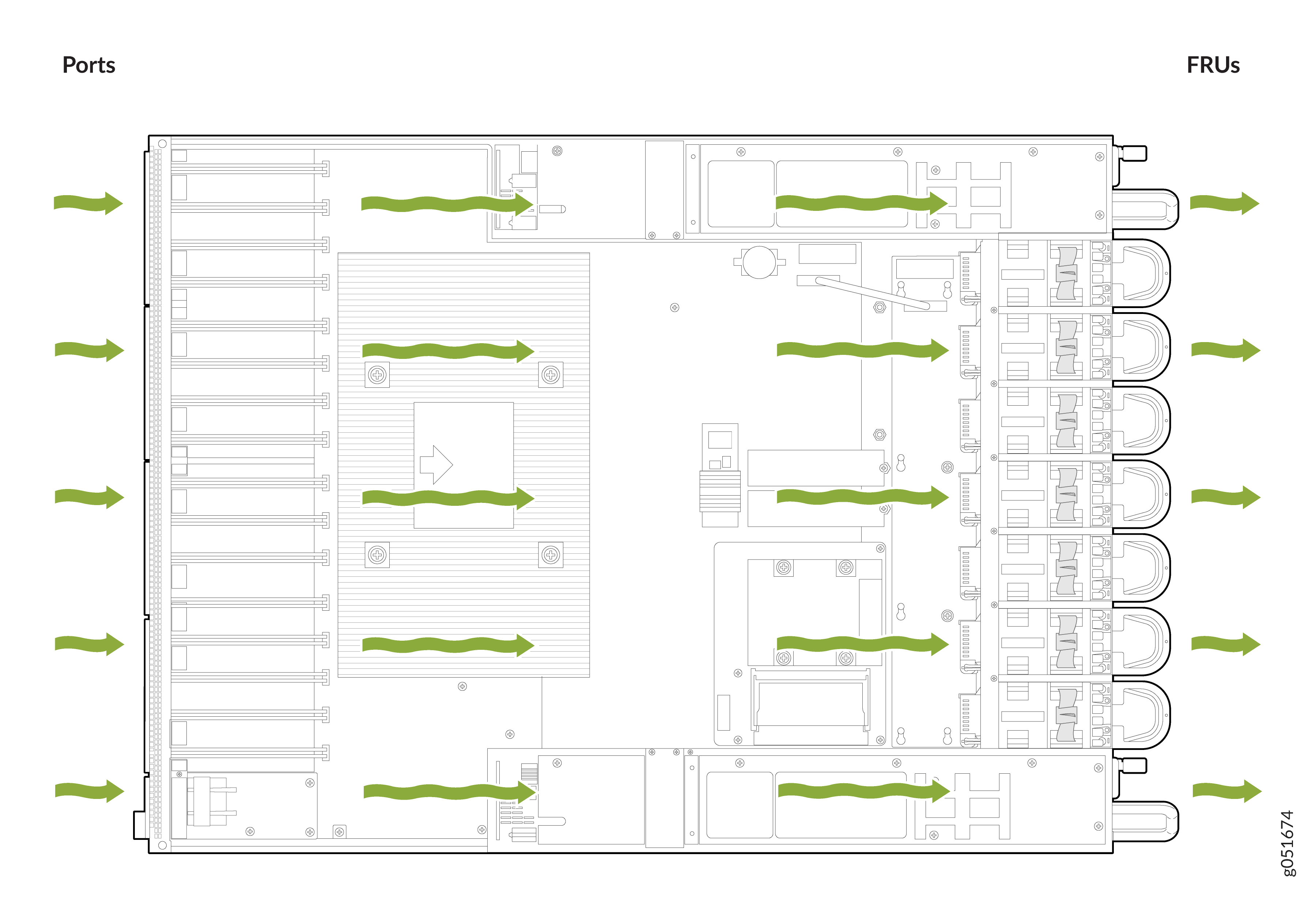
Airflow
The switch has a front-to-back (AFO) airflow design cooling system. The switch pulls air through the front of the chassis toward the fan modules, and exhausts the air from the rear of the switch.
Power Supply Cooling System
The QFX5241-32OD PSUs are installed at the rear of the chassis. The PSUs are self-cooling. Each PSU has its own fan and is cooled by its own internal cooling system. The PSUs in a QFX5241-32OD switch support front-to-back airflow (AFO).