QFX5220-32CD Port Panel
The port panel of the QFX5220-32CD has 32 high-speed ports that support transmission at 400-Gbps, 100-Gbps, or 25-Gbps speeds. It also has 2 dedicated ports for 10 Gbps.
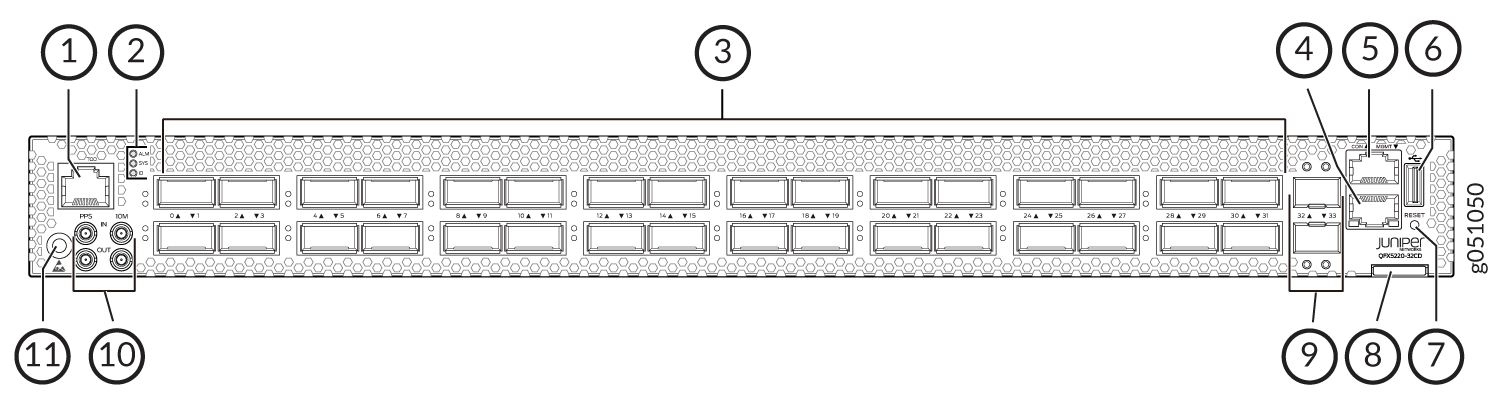
1 — RJ-45 connection to grandmaster clock | 7 — Reset button (do not use unless directed by JTAC) |
2 — Chassis status LEDs | 8 — Chassis serial number pull-out |
3 — 32 high-speed ports-QSFP-DD cages | 9 — 10 Gigabit Ethernet ports–SFP+ cages |
4 — RJ-45 management port (100 Mbps/1000 Mbps/ 10000 Mbps) | 10 — Clock input and output connectors (10 MHz and 1 PPS) |
5 — RJ-45 console port | 11 — ESD grounding point |
6 — USB port (USB 2.0/3.0 standard) |
Network Ports
The QFX5220-32CD network ports (0 to 31) support:
-
400-Gbps QSFP-DD direct attach copper (DAC) cables
-
400 Gbps active optic cable (AOC) (starting in Junos OS Evolved Release 19.3R2)
-
100-Gbps QSFP28 transceivers
-
100 Gbps active optic break outcables (AOCBO) QSFP28 to four SFP25G interfaces
-
40-Gbps QSFP+ to SFP+ DACBO cables (40-Gbps breaks out to 4 independent 10-Gbps connections)–Junos OS Evolved Release 20.2R1 and later
The 10-Gbps network ports 32 and 33 support small form-factor plus (SFP+) transceivers.
Setting Port Speed and Channelization
The default port speed for ports 0 through 31 is 400 Gbps. Only QSFP-DD optics inserted in these ports will link without configuration.
|
Transceiver, DAC, AOC, DACBO, or AOCBO |
Sets Default Speed to |
|---|---|
|
QSFP-DD |
400 Gbps, link up |
|
QSFP28 |
400 Gbps, link down |
|
QSFP |
400 Gbps, link down |
|
SFP+ (ports 32 and 33 only) and management port |
10 Gbps, link up |
The QFX5220-32CD network ports (0 to 31) support:
- The last two SFP+ ports cannot support 1GbE modules. These two ports support only 10GbE modules.
If a port already has a speed configured, you can manually configure the ports. To
set the speed, use the set chassis fpc FPC number pic
pic number port port number speed
25|40|100|200|400
configuration mode CLI
command. For example, to set port 2 to 100 Gbps:
[edit chassis]
user@host#set chassis fpc 0 pic 0 port 2 speed 100g
On QFX5220-32CD devices, there is a single FPC and PIC, which is always 0.
After you set a port speed, you can channelize the port into 4 independent 25-Gigabit
Ethernet interfaces by configuring the number of subports and speed. You should use
the set chassis fpc FPC number pic pic
number port port number number-of-sub-ports
1|2|3|4
command. For example, to configure
100-Gbps port 4 to four independent 25-Gbps interfaces:
[edit chassis]
user@host#set chassis fpc 0 pic 0 port 4 speed 25g number-of-sub-ports 4
Be sure to save and commit your changes.
An incorrectly configured port can cause unexpected port and switch behavior. The
system software does not check whether the port speed or the attached optic are
supported at the time of the commit. Use the show chassis
alarms and the show chassis pic fpc-slot 0 pic-slot
0 to locate incorrectly configured ports. See Configuration Changes Leading to Unexpected QFX5220 Behavior.
QFX5220-32CD Network LEDs
The high-speed QSFP-DD network ports use a single bi-colored LED to indicate link status, activity on the link, or a fault condition. The 10-Gbps SFP+ ports have separate bi-colored LEDs; the left LED indicates link and activity and the right LED indicates fault conditions.
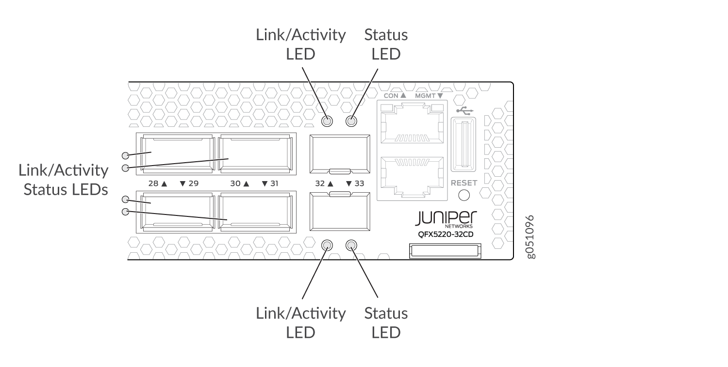
Table 2 describes the various states of the network port LED for the high-speed ports. Table 3 describes how to interpret the link and activity LED and the status LEDs for the SFP+ ports.
|
Color |
State |
Channelized |
Description |
|---|---|---|---|
|
Unlit |
Off |
No |
Off is the default mode. The LED can be unlit even when power is present and a transceiver is present in the port.
|
|
Yes |
The port is administratively disabled. |
||
|
Green |
On steadily |
No |
A 400-Gbps or 100-Gbps link is established, but there is no activity. |
|
Yes |
All channels or subports have link established but there is no activity. |
||
|
Flashing |
No |
A 400-Gbps or 100-Gbps link is established, and there is link activity. |
|
|
Yes |
All channels or subports have links established and there is link activity. |
||
|
All LEDs Blipping (slow flashing) |
Either |
Indicates that the beacon feature is activated (service request). |
|
|
Amber |
Blinking |
Either |
One or more interface or connection errors has occurred. |
|
Flashing |
Yes |
At least one channel or subport has a link, but not all channels or subports have links established. |
|
LED |
Color |
State |
Description |
|---|---|---|---|
|
Link/Activity |
Off |
Link down |
Link down—The port does not have a connection. |
|
Green |
On steadily |
Link up—The port has a connection, but there is no activity. |
|
|
Flashing |
Active link—The port has a connection and there is activity. |
||
|
Blipping (slow flashing) |
Beacon–The port has a service request. |
||
|
Status |
Green |
On steadily |
The port is configured for 10 Gbps. |
|
Amber |
Blinking |
Fault–The port has an interface error. |