QFX5210-64C Port Panel
QFX5210-64C Port Panel Overview
The port panel of the QFX5210-64C has 64 quad small-form factor pluggable plus (QSFP28) ports for port configuration speeds of 100 -Gigabit Ethernet or 40-Gigabit Ethernet. It also has two small-form factor plus (SFP+) ports for 1-Gigabit Ethernet or 10-Gigabit Ethernet interfaces. The QSFP28 ports can be configured either as 100-Gigabit Ethernet ports (default) or as 40-Gigabit Ethernet ports. The ports auto-sense the transceiver type and set the speed accordingly. Any of the 64 ports 0 through 63 can be configured as uplinks or as access ports.
Figure 1 shows the port panel of the QFX5210-64C.
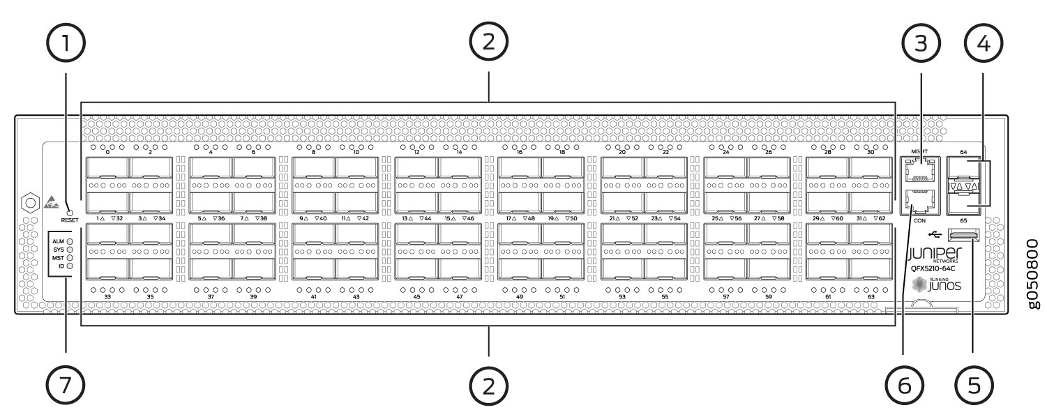
1 — Reset button | 5 — USB port |
2 — 64 QSFP28 ports and 2 SFP+ ports | 6 — Console port |
3 — Management port | 7 — Chassis alarm LEDs |
4 — 10-Gigabit Ethernet SFP+ ports |
- Network Ports
- Channelizing Interfaces
- Channelization on QFX5210-64C Running Initial Junos Releases
- Channelization on QFX5210-64C Running Junos OS 19.1R1 and Later
Network Ports
Network device ports ( 0 through 31) support:
-
100-Gbps QSFP28 transceivers
-
40-Gbps QSFP+ transceivers
-
QSFP28 direct attach copper (DAC) cables
-
QSFP+ DAC cables
-
QSFP+ to SFP+ DACBO cables (40 Gbps breaks out to 10 Gbps)
-
QSFP28 to QSFP+ DACBO cables (100 Gbps breaks out to 25 Gbps)
Network device ports ( 32 through 63) support:
-
100 Gbps QSFP28 transceivers
-
40 Gbps QSFP+ transceivers
-
QSFP28 direct attach copper (DAC) cables
-
QSFP+ DAC cables
High wattage optics (greater than 3.5 W) are only supported in ports 32 to 63 on QFX5210-64C-AFI. There is no restriction on high wattage optics on QFX5210-64C-AFO.
On QFX5210-64C switches, it takes 20-30 seconds to bring down the interfaces
using set interface 0/0x disable command when you install a 64
x QSFP-100GBASE-LR4-T2 optical transceiver.
Channelizing Interfaces
The method of channelizing QFX5210-64C ports and the behavior of the ports and interfaces is Junos OS release dependent. For switches running Junos OS releases before Junos OS 19.1R1, see Channelization on QFX5210-64C Running Initial Junos Releases. For switches running Junos OS 19.1R1 and later, see Channelization on QFX5210-64C Running Junos OS 19.1R1 and Later.
If a QFX5210-64C is fully populated with optics and is using 25 Gbps or 10 Gbps channelization, it can take up to 7 minutes for the ports to link.
Channelization on QFX5210-64C Running Initial Junos Releases
The QFX5210-64C initial offering ran Junos OS 18.1R1. Until the behavior change in 19.1R1, the 64 ports are divided into two ranges:
-
Lower order ports (0–31)
-
Higher order ports (32–63)
When a lower port is channelized, the corresponding higher port is disabled to regulate the number of allowed phy ports to 128. For example, port 0 disables port 32 and port 31 disables port 63. See Table 1.
-
All 64 ports (0 to 63) can operate as either 40-Gigabit Ethernet or 100-Gigabit Ethernet.
-
When ports 0 through 31 are configured for 40-Gigabit Ethernet and a 4x10G breakout cable is inserted, the system converts the port into 4 independent 10-Gigabit Ethernet ports. Ports 32 to 63 are not eligible for 4x10G breakout.
-
When ports 0 through 31 are configured for 100-Gigabit Ethernet and a 4x25G breakout cable is detected, the system converts the port into 4 independent 25-Gigabit Ethernet ports. When a 2x50G breakout cable is detected, the system converts the port into 2 independent 50-Gigabit Ethernet ports.
-
When ports 32 through 63 are configured for 100-Gigabit Ethernet and a 2x50G breakout cable is detected, the system converts the port into 2 independent 50-Gigabit Ethernet ports.
Port combinations can be mixed up to the system maximum of 128 phy ports.
Changing the channelization mode causes the FPC to reboot. Because there can be a slight loss of data while the FPC reboots, we recommend that you only configure the changes during a maintenance window.
To channelize the ports, manually configure the port speed using
the set chassis fpc 0 pic 0 port port-number channel-speed speed
command,
where the speed can be set to 10G, 25G, 40G, 50G, or 100G.
|
Mode |
Ports 0 to 31 |
Ports 32 to 63 |
|---|---|---|
|
Default, not channelized |
40 Gbps, 100 Gbps |
40 Gbps, 100 Gbps |
|
Channelized |
10 Gbps, 25 Gbps, 40 Gbps, 50 Gbps, 100 Gbps |
40 Gbps, 50, Gbps, 100 Gbps |
Channelization on QFX5210-64C Running Junos OS 19.1R1 and Later
Beginning in Junos OS 19.1R1, system mode configuration is no longer necessary to channelize ports. Systems upgrading to this release and later ignore previous system mode settings.
-
Dechannelized ports or clear ports behavior
All 64 ports (0 to 63) auto-sense the transceiver speed and set the port speed to either 40 Gbps or 100 Gbps. The default port speed is 100 Gbps. No ports are channelized.
-
Channelized behavior
You can channelize ports with QFX5210-64C; however the channelization is not restricted only to the first 32 front panel ports. It is better to use ports of the lower order to easily calculate ports that are used and unused. Overall, QFX5210-64C supports 64 physical ports that are mapped to 128 BCM ports and these internal ports are divided into 4 blocks.
Since each block accommodates 32 logical ports, each block is mapped with 32 logical ports and 16 user ports. You can channelize 8 user ports per pipe (4X25G or 4X10G), which utilizes 32 logical ports in that pipe. To achieve this, disable the required higher-order user ports on that pipe.
You can use these steps to calculate this easily:
-
The first five ports that are channelized utilize all the BCM ports, and leave one free logical port; also doesn't disable any ports.
-
From the sixth port that gets channelized, every new port which gets channelized consumes four extra logical ports. In this case, the first higher-order physical ports that are extra, get disabled.
Figure 2: Improved Flexible Port Channelization Blocks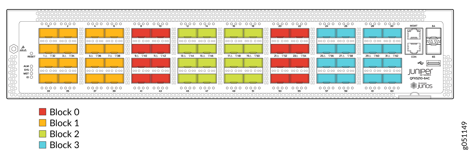
-
| 0 | 1 | 2 | 3 | 4 | 5 | 6 | 7 |
|---|---|---|---|---|---|---|---|
| 32 | 33 | 34 | 35 | 36 | 37 | 38 | 39 |
-
No ports are disabled and one logical port is free.
- Ports (5 to 7, 34 to 39) can be used as 40G or 100G interfaces.
| 0 | 1 | 2 | 3 | 4 | 5 | 6 | 7 |
|---|---|---|---|---|---|---|---|
| 32 (disabled) | 33 (disabled) | 34 | 35 | 36 | 37 | 38 | 39 |
-
Six channelized ports utilize 24 logical ports.
- Ports in the higher order (32 and 33) get are disabled and the eight remaining ports (6,7, and 34 to 39) can be used as 40G or 100G interfaces.
| 0 | 1 | 2 | 3 | 4 | 5 | 6 | 7 |
|---|---|---|---|---|---|---|---|
| 32 (disabled) | 33 (disabled) | 34 (disabled) | 35 (disabled) | 36 (disabled) | 37 | 38 | 39 |
-
Seven channelized ports utilize 28 logical ports.
- Ports in the higher order (32 to 36) get disabled and the four remaining ports (7 and 37 to 39) can be used as 40G or 100G interfaces.
| 0 | 1 | 2 | 3 | 4 | 5 | 6 | 7 |
|---|---|---|---|---|---|---|---|
| 32 (disabled) | 33 (disabled) | 34 (disabled) | 35 (disabled) | 36 (disabled) | 37 (disabled) | 38 (disabled) | 39 (disabled) |
-
Eight channelized ports utilize 32 logical ports.
- Ports in the higher order (32 to 39) get disabled and no remaining ports can be used as 40G or 100G interfaces.
-
Note:
Use the lower-order ports (0-31) for port channelization and expect all higher-order ports (32-63) to get disabled when you use eight channelized ports per block.
QFX5210 Network Port LEDs
The Link/Activity LED configuration for QFX5210 switches use bi-colored LEDs. The link LED indicates link activity or a fault. See Table 6.
|
Port Type |
Indicators |
Location |
|---|---|---|
|
QSFP28 for 40 Gbps, 100 Gbps speeds and breakouts |
Channelization LinkStatus |
There are four bi-color LEDs for each QSFP+ port. For 100 Gbps speeds, only the first LED is lit when the interface is configured for 100-Gigabit Ethernet and connected to a QSFP28 transceiver. All four LEDs are lit when the interface is configured for 10-Gigabit Ethernet or 25-Gigabit Ethernet and the port is connected using a 40-Gigabit optical splitter cable or a copper DACBO cable. 
|
|
SFP+ |
Link Status |
There are two bi-color LEDs for each SFP+ port. 
|
Table 7 describes how to interpret the Link/Activity QSFP28 port LEDs.
|
Color |
State |
QSFP28 Description |
|
|---|---|---|---|
|
Unlit |
Off |
The port is administratively disabled, there is no power, the link is down, or there is a fault. |
|
|
When configured for 25-Gigabit Ethernet, the LED remains unlit only if all four of the 25-Gigabit Ethernet QSFP+ breakout links are down. |
|||
|
Green |
On steadily |
A link is established, but there is no link activity. |
|
|
When configured for 25-Gigabit Ethernet, the LED is lit green when at least one of the four 25-Gigabit Ethernet QSFP+ breakout links is established. |
|||
|
Blinking |
A link is established, and there is link activity. |
||
|
When configured for 25-Gigabit Ethernet, the LED is lit green when at least one of the four 25-Gigabit Ethernet QSFP+ breakout links is established. |
|||
Beacon is not supported on a per-port basis on QSFP28 ports.
Table 8 describes how to interpret the Link/Activity SFP+ port LEDs.
|
Color |
State |
SFP+ Description |
|
|---|---|---|---|
|
Unlit |
Off |
The port is administratively disabled, there is no power, the link is down, or there is a fault. |
|
|
Green |
On steadily |
A link is established, but there is no link activity. |
|
|
Blinking |
A link is established, and there is link activity. |
||
|
Amber |
Blinking |
The beacon function is enabled on the port. |
|