QFX5200 Port Panels
QFX5200-32C and QFX5200-32C-L Port Panel
The port panel of the QFX5200-32C and QFX5200-32C-L supports port configuration speeds of 100, 50, 40, 25, or 10 Gigabit Ethernet. The QFX5200-32C and QFX500-32C-L uses 28-Gbps quad small-form factor pluggable plus (QSFP28) sockets that are configured as 100 Gigabit Ethernet ports by default. Any of the 32 ports 0 through 31 can be configured as uplinks or as access ports.
Figure 1 shows the port panel of the QFX5200-32C and QFX5200-32C-L.
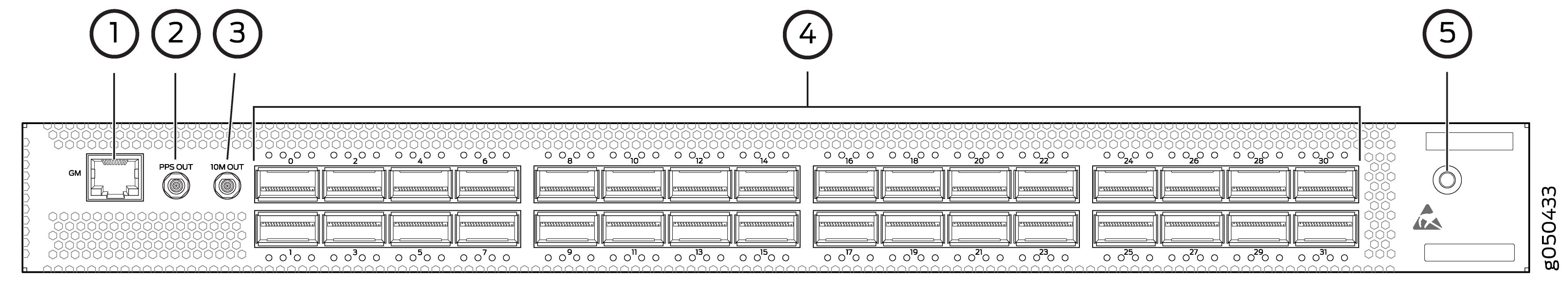
1 — RJ45 connection to grand master clock | 4 — 32 QSFP28 ports |
2 — 1 pulse per second (PPS) output connection for clocking messages | 5 — Electrostatic discharge (ESD) terminal |
3 — Output clock at 10 Mhz |
This topic describes:
Network Ports
The QFX5200-32C and QFX5200-32C-L network ports, ( 0 to 31) support:
-
100 Gbps QSFP28 transceivers
-
40 Gbps QSFP+ transceivers
-
100 Gbps active optical cables (AOC)
Note:For interoperability with other QFX Series switches, ensure auto-speed-detection on the QFX5200-32C is disabled.
-
40 Gbps AOC
-
QSFP28 direct attach copper (DAC) cables
-
QSFP+ DAC cables
-
(QFX5200-32C only) QSFP+ to QSFP+ direct attach copper break out (DACBO) cables (100 Gbps breaks out to 50 Gbps or 25 Gbps)
-
(QFX5200-32C only) QSFP+ to SFP+ DACBO cables (40 Gbps breaks out to 10 Gbps)
Starting in Junos OS Release 19.3R1, you can also use a QSFP+ to SFP+ adapter (QSA) in the QSFP+ ports to provide either 40 Gigabit Ethernet or 4x10 Gigabit Ethernet speeds.
Channelizing Interfaces
For downstream traffic, the QFX5200-32C has 32 physical or 128 logical ports (32 x 4) that can be used for port channelization. The 100 Gigabit Ethernet ports can be channelized using breakout cables either to 2 independent downstream 50 Gigabit Ethernet or to 4 independent 25 Gigabit Ethernet ports. The default 100 Gigabit Ethernet ports can also be configured as 40 Gigabit Ethernet and in this configuration can either operate as dedicated 40 Gigabit Ethernet ports or can be channelized to 4 independent 10 Gigabit Ethernet ports using breakout cables.
The QFX5200-32C ports support auto-channelization starting in Junos OS Release 15.1X53-D230.
The QFX5200-32C-L supports channelization by configuration starting in in Junos OS Evolved Release 18.3R1.
Network Port LEDs
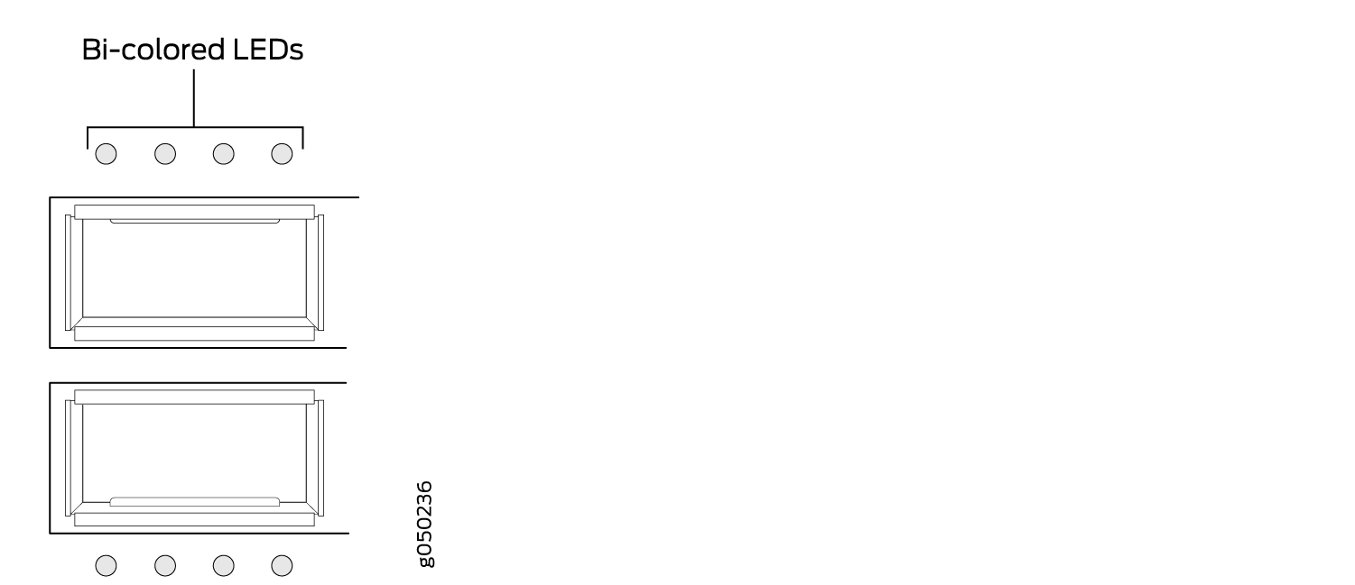
The Link/Activity LED configuration for QFX5200-32C and QFX5200-32C-L switches use bi-colored LEDs. The link LED indicates link activity or a fault. See Table 1.
|
Port Type |
Indicators |
Location |
|---|---|---|
|
QSFP28 and QSFP+ |
SpeedLinkStatusChannelization |
Figure 2: QFX5200-32C and
QFX5200-32C-L Port LEDs
|
Table 2 describes how to interpret the QSFP28 port LEDs.
|
Color |
State |
QFX5200-32C and QFX5200-32C-L Description |
|
|---|---|---|---|
|
Unlit |
Off |
The port is administratively disabled, there is no power, the link is down, or there is a fault. |
|
|
When configured for 25-Gigabit Ethernet, the LED remains unlit only if all four of the 25-Gigabit Ethernet QSFP+ breakout links are down. |
|||
|
Green |
On steadily |
A link is established, but there is no link activity. |
|
|
When configured for 25-Gigabit Ethernet, the LED is lit green when at least one of the four 25-Gigabit Ethernet QSFP+ breakout links is established. |
|||
|
Blinking |
A link is established, and there is link activity. |
||
|
When configured for 25-Gigabit Ethernet, the LED is lit green when at least one of the four 25-Gigabit Ethernet QSFP+ breakout links is established. |
|||
|
Amber |
Blinking |
The beacon is enabled on the port. |
|
As shown in Table 3, there are four bi-color LEDs for each QSFP+ port. The first LED is used and the remaining LEDs are not used when the interface is configured for 100-Gigabit Ethernet and connected to a QSFP28 transceiver. All four LEDs are used when the interface is configured for 25-Gigabit Ethernet and the port is connected using an optical splitter cable or a copper DACBO cable. Table 3 describes how to interpret the QSFP+ LEDs.
|
Color |
State |
Description |
|---|---|---|
|
Unlit |
Off |
The port is administratively disabled, there is no power, the link is down, or there is a fault. Note:
When configured for 10-Gigabit Ethernet, the LED remains unlit only if all four of the 10-Gigabit Ethernet SFP+ breakout links are down. |
|
Green |
On steadily |
A link is established, but there is no link activity. Note:
When configured for 10-Gigabit Ethernet, the LED is lit green when at least one of the four 10-Gigabit Ethernet SFP+ breakout links is established. |
|
Blinking |
A link is established, and there is link activity. Note:
When configured for 10-Gigabit Ethernet, the LED is lit green when at least one of the four 10-Gigabit Ethernet SFP+ breakout links is established. |
|
|
Amber |
Blinking |
All four LEDs blink to indicate the beacon function was enabled on the port. |
QFX5200-48Y Port Panel
The port panel of the QFX5200-48Y supports port configuration speeds of 100 or 40 Gigabit Ethernet, and 25 or 10 Gigabit Ethernet. The QFX5200-48Y has 48 small form-factor pluggable 28 (SFP28) ports (0 through 47) that can be configured as either 10 Gigabit Ethernet or 25 Gigabit Ethernet. The QFX5200-48Y also has six quad small form-factor pluggable (QSFP28) ports (48 through 53 that can be configured as either 100 Gigabit Ethernet or 40 Gigabit Ethernet. The SFP28 ports default to 10 Gigabit Ethernet but can be configured in groups of four ports to 25 Gbps speeds. The QSFP28 ports auto-sense the speed of inserted optics and configure the port to the appropriate speed for that transceiver. See Figure 3.
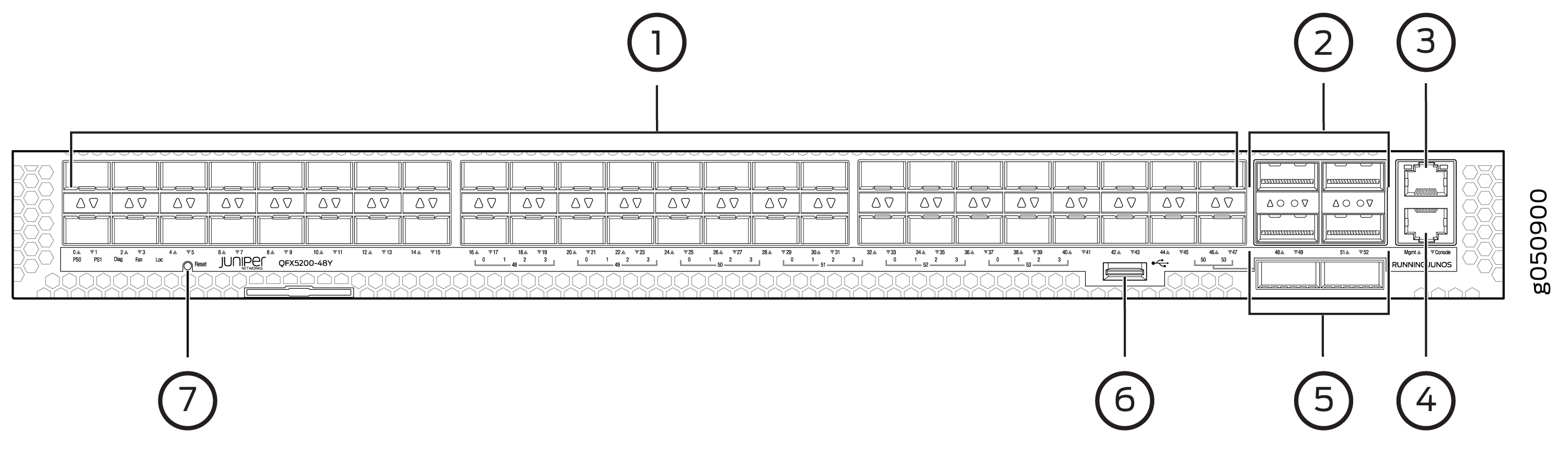
1 — 48 SFP28 ports | 5 — 2 QSFP28 ports |
2 — 4 QSFP28 ports | 6 — USB port |
3 — RJ45 management port | 7 — System status LEDs |
4 — RJ45 console |
Network Ports
The QFX5200-48Y ports, (0 to 47) are normally used as access ports. They support:
-
10 Gbps SFP+ transceivers
-
10 Gbps direct attach copper (DAC) cables
-
25 Gbps SFP28 transceivers
-
25 Gbps SFP28 DAC cables
The QFX5200-48Y ports, (48 to 53) are normally used as uplinks. They support:
-
25 Gbps active optical cables (AOC)
-
40 Gbps QSFP+ transceivers
-
40 Gbps DACBO cables (40 Gbps to 10 Gbps)
-
100 Gbps QSFP28 transceivers
-
100 Gbps AOC
Port Groups
The 48 SFP28 ports default to 10 Gigabit Ethernet but can be configured to 25 Gigabit Ethernet by port groups. The SFP28 ports are divided into 12 port groups, with four contiguous ports in each port group. Each port group can be configured to either 10 Gbps or 25 Gbps speeds, but mixing port speeds within a port group is not allowed. See Table 4
|
Port Groups |
|---|
|
0 – 3 |
|
4 – 7 |
|
8 – 11 |
|
12 – 15 |
|
16 – 19 |
|
29 – 23 |
|
24 – 27 |
|
28 – 31 |
|
32 – 35 |
|
36 – 39 |
|
40 – 43 |
|
44 – 47 |
Use the set chassis fpc command to set an SFP28 port
group to either 10 Gbps or 25 Gbps speeds. You will receive a warning
message that you are changing the port configuration for the four
ports. Committing the change does cause the FPC to reboot. For example,
to change ports 0 through 3 to 25 Gbps from the default 10 Gbps, issue the following command:
[edit]
user@host# set chassis fpc 0 pic 0 port 0 speed 25g
user@host# commit
warning: 25g config will be applied to ports 0 to 3
{master:0}[edit]
root@sw-symphony-03# commit
configuration check succeeds
commit complete
Network Port LEDs
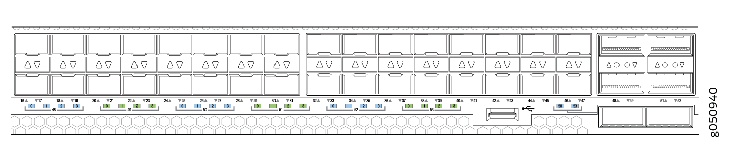
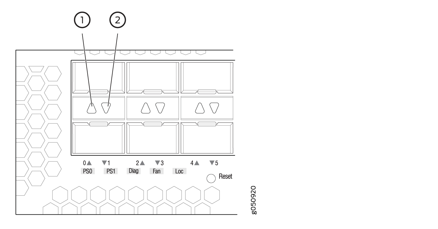
The QFX5200-48Y uses bi-colored LEDS to indicate link and activity on the port. SFP28 ports have a single green/amber LED. QSFP28 ports have four blue/amber ports. Only the first (left-most) LED is used. See Table 5 and Table 6.
The up and down arrow LEDs for QSFP28 ports 48, 49, 51, and 52 are not used.
|
Port Type |
Indicators |
Location |
|---|---|---|
|
QSFP28 |
SpeedLinkStatus |
Figure 4: QFX5200-48Y QSFP28
Port LEDs
|
|
SFP28 |
SpeedLinkStatus |
Figure 5: QFX5200-48Y SFP28 Port
LEDs
|
|
Transceivers Supported |
Color |
State |
LED Description |
|
|---|---|---|---|---|
|
SFP28 |
Unlit |
Off |
The port is administratively disabled, there is no power, the link is down, or there is a fault. |
|
|
Amber |
On steadily |
A link is established for 10 Gbps or 25 Gbps, but there is no activity. |
||
|
Blinking |
A link is established for 10 Gbps or 25 Gbps and there is link activity. |
|||
|
QSFP28 |
Unlit |
Off |
The port is administratively disabled, there is no power, the link is down, or there is a fault. |
|
|
Green |
On steadily |
A link is established for 40 Gbps or 100 Gbps, but there is no activity. |
||
|
Blinking |
A link is established for 40 Gbps or 100 Gbps and there is link activity. |
|||