Replace Power Supply Units on the QFX5140
Maintaining the QFX5140 includes removing and installing the power supply units (PSUs).
The power supply units (PSUs) on the QFX5140 are hot-removable and hot-insertable field-replaceable units (FRUs) with support for 1+1 redundancy. You can remove and replace a PSU without powering off the QFX5140 or disrupting the device functions.
Do not mix AC and DC power supplies within the same chassis, and avoid combining AFO and AFI modules in a single system configuration.
Per TSB #XYZ, PSU redundancy support depends on the unit's production date. Early production units support PSU redundancy only with high-line input power (200–240 VAC), while all later production units support PSU redundancy with both low-line (100–127 VAC) and high-line (200–240 VAC) AC input power.
Before you remove or install a PSU, ensure that you have taken the necessary precautions to prevent electrostatic discharge (ESD) damage.
Ensure that you have the following parts and tools:
-
An ESD grounding strap
-
An antistatic bag or an antistatic mat
-
A replacement PSU
-
A blank cover panel (in case you're not replacing the PSU)
-
(For DC power supply) Philips (+) screwdriver, number 2
Replace an AC PSU on the QFX5140
Remove the JPSU-1600W-1UACAFO
This topic guides you through the steps to remove the JPSU-1600W-1UACAFO AC power supply from the QFX5140 Switch.
Avoid leaving the PSU slot empty for more than 30 minutes when the device is operational. For optimal airflow, all PSUs must be installed in the chassis.
If you need to replace all the power supplies installed in your QFX5140, you must power off the QFX5140 before removing the power supplies.
To remove the JPSU-1600W-1UACAFO:
-
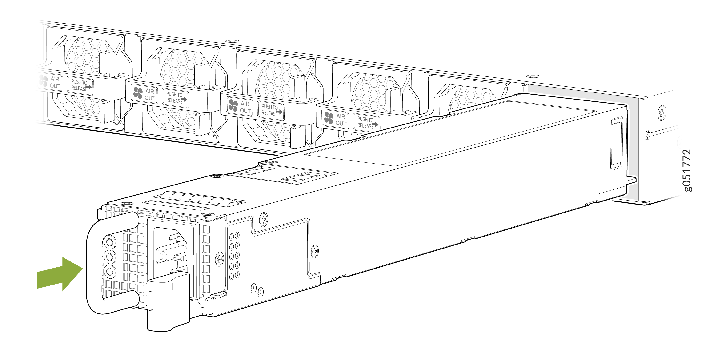
Pull the PSU straight out of the chassis.
Figure 1: Remove the AC PSU
Install the JPSU-1600W-1UACAFO
To install the JPSU-1600W-1UACAFO:
-
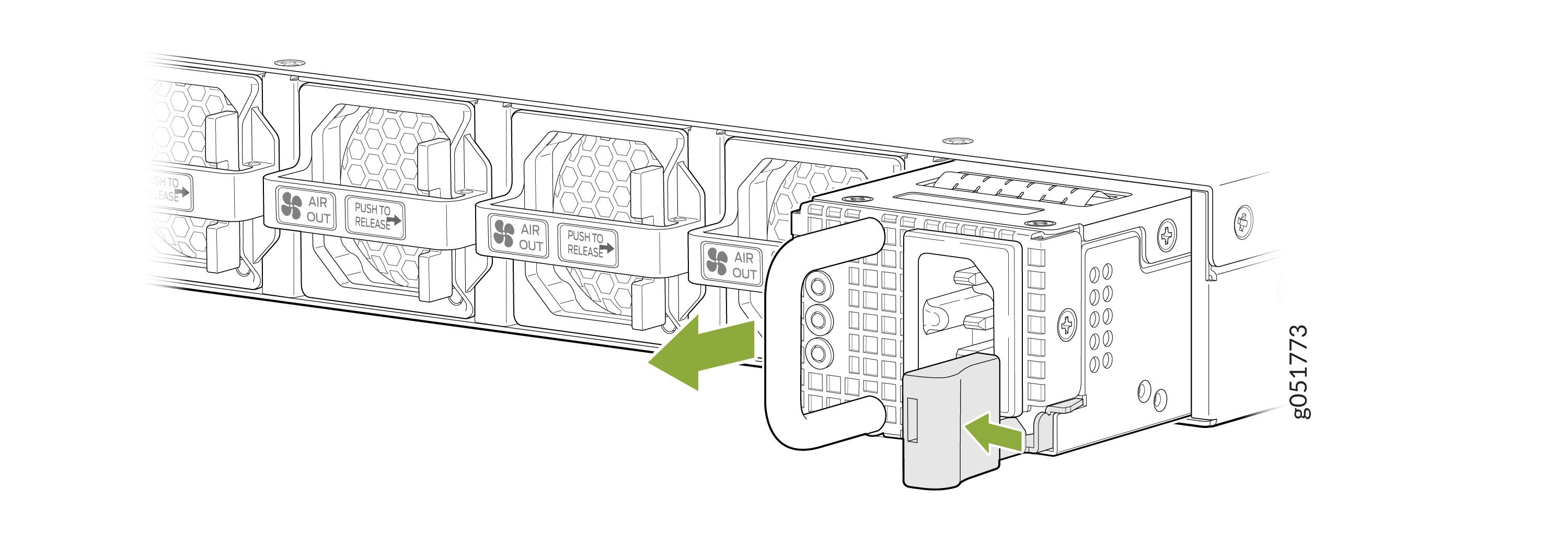
Using both hands, place the PSU in the PSU slot on the rear panel of
the router. Slide the PSU straight into the chassis until the PSU is
fully seated in the chassis slot and the release latch slides into
place. Ensure that the PSU faceplate is flush with the adjacent PSU
faceplate. See Figure 2.
Figure 2: Install the AC PSU