Install the QFX5140
This topic guides you through the steps to install the QFX5140 on four-post racks.
You can mount the QFX5140:
-
On four posts of a 19-in. rack. A four-post rack mounting kit is included with the QFX5140 shipment.
Complete these prerequisites before you mount the device:
-
Prepare the site for installation.
-
Ensure that the site has adequate clearance for both airflow and hardware maintenance.
Figure 1: Clearance Requirements for QFX5140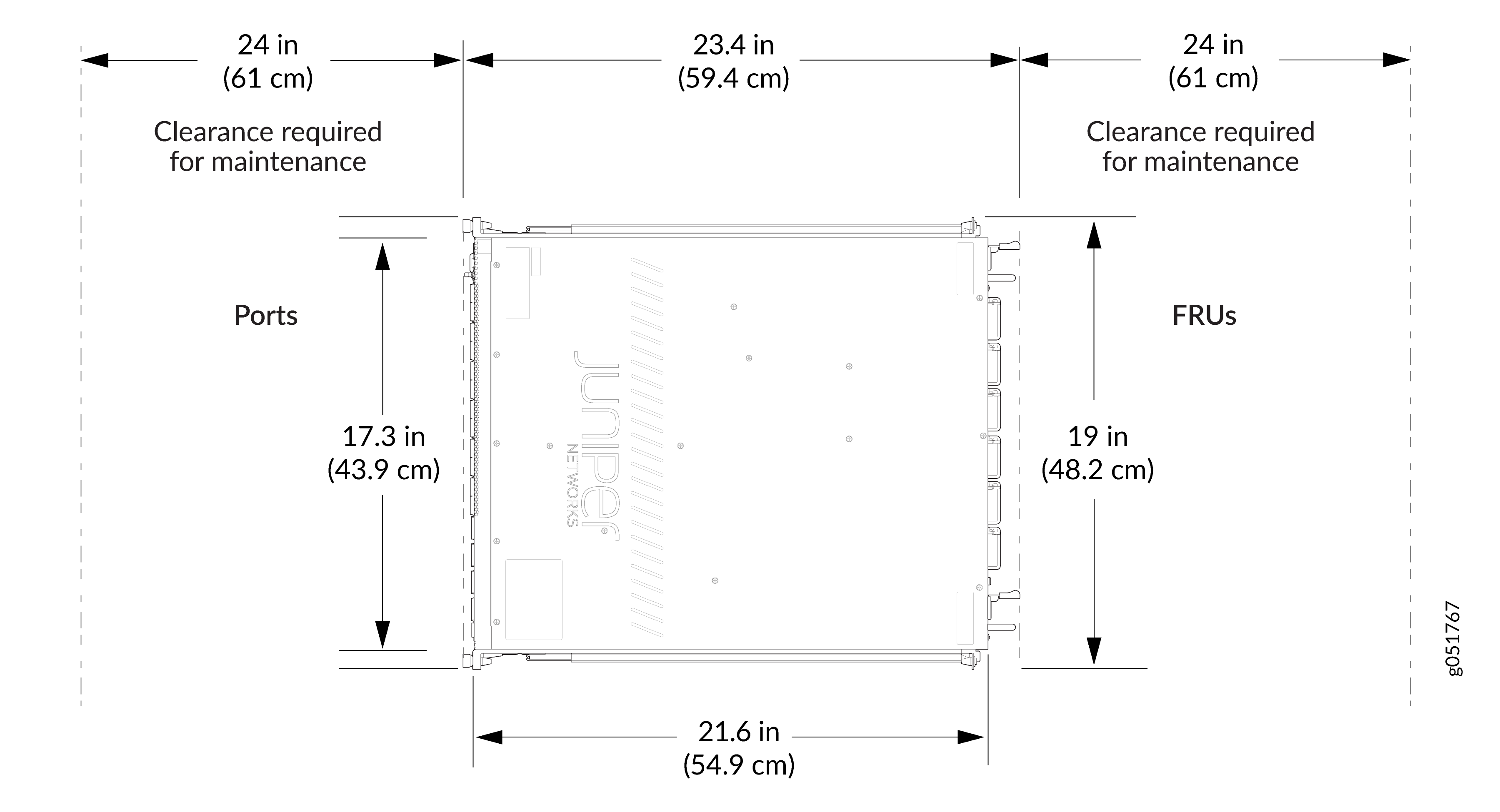
-
Unpack the device as described in Unpack the QFX5140.
-
Ensure that you have all the parts and tools available to mount the QFX5140 in a rack. See the instructions for the rack installation kit that you are using:
-
A qualified technician must verify that the rack or cabinet is strong enough to support the device's weight before mounting the device. Have the technician also verify that the rack or cabinet has adequate support at the installation site.
-
If you are installing more than one device on a rack or in a cabinet, install the first device at the bottom of the rack.
QFX5140 requires two people for installation, one person to lift the device into place and another person to attach the device to the rack. If you are installing the QFX5140 above 60 in. (152.4 cm) from the floor, you can remove the power supplies and fan modules to minimize the weight before attempting to install the QFX5140. A fully loaded chassis (with an AC power supply) weighs approximately 24.5 lb (11.1 kg).
Ensure that you support the rear of the chassis throughout the process of mounting the device on the rack.
Mount the QFX5140 on a Four-Post Square-Holed Rack Using the JNP-4P-TL-1RU-RMK
Mount the QFX5140 on a four-post square-holed rack on your site by following the recommended procedure below.
Ensure that you have the following tools and parts available:
-
An ESD grounding strap (provided)
-
A pair of front-mounting and rear-floating rails (provided with the RMK)
These mounting rails attach to the front and rear rack posts.
-
A pair of chassis brackets (provided with the RMK)
You must attach these brackets to the device if not preinstalled.
Juniper provides the four-post rack mounting kit (JNP-4P-TL-1RU-RMK) with the QFX5140. If the four-post kit is lost or damaged, you can order a replacement.
To mount the device on four posts of a square-holed rack using the JNP-4P-TL-1RU-RMK rack mount kit:
-
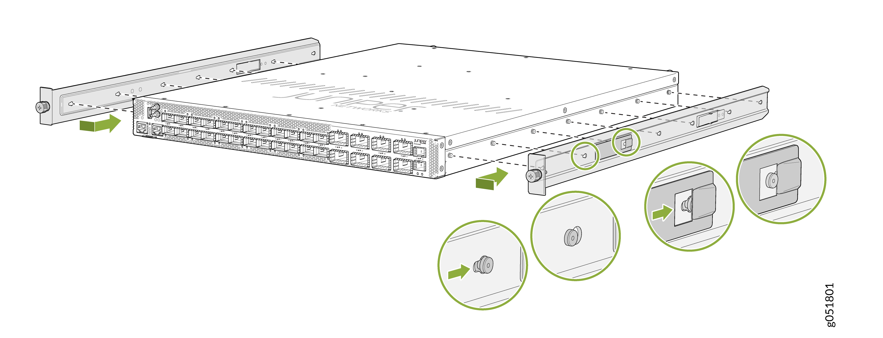
Install the chassis bracket to the chassis by aligning the keyholes on the
chassis bracket with the shoulder screws on the chassis. Slide the chassis
bracket toward the rear of the chassis.
Figure 2: Install the Chassis Brackets
-
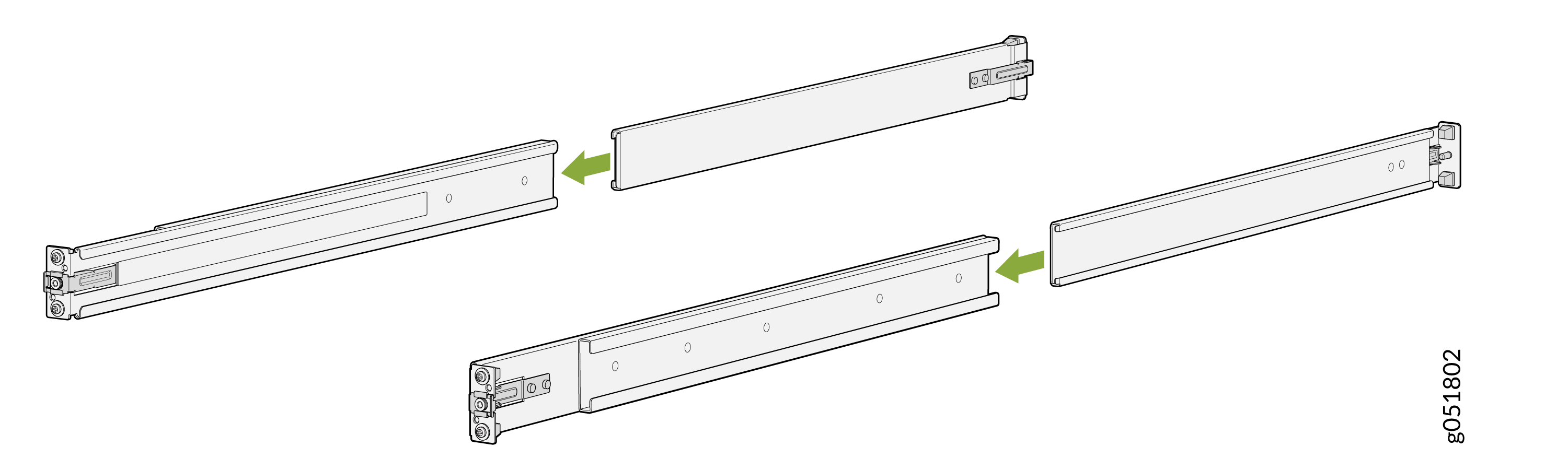
Assemble the mounting rails by sliding the rear-floating rails into the
respective front-mounting rails.
Figure 3: Assemble the Mounting Rails
-
Install the mounting rails on the four-post rack:
-
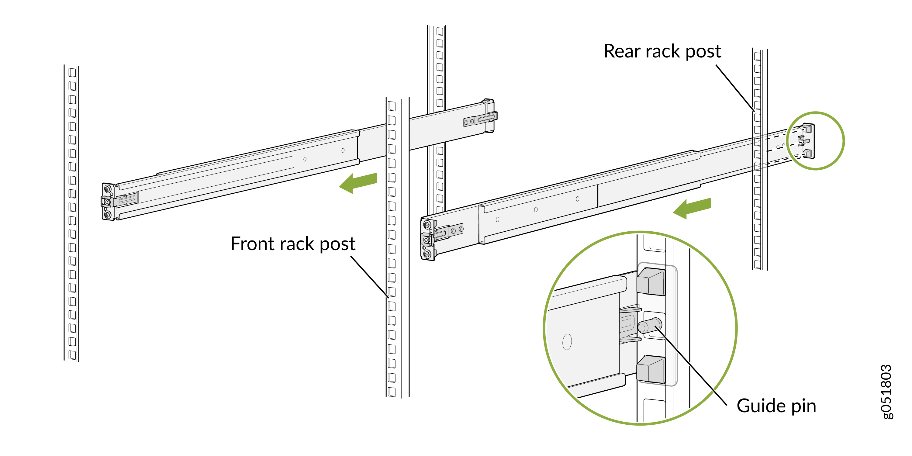
Use the guide pin to align the guide blocks of the rear-floating
rails with the corresponding rear post holes. Pull the rear-floating
rails toward the front of the rack to lock the rail in place. You
will hear a distinct click sound when the latch locks into the
corresponding rack holes.
Figure 4: Secure Rear-Floating Rails
-
Align the guide blocks of the front-mounting rails with the front
post holes. Push the front-mounting rails toward the rear of the
rack to lock the rails in place. You will hear a distinct click
sound when the latch locks into the corresponding rack holes.
Figure 5: Secure Front-Mounting Rails
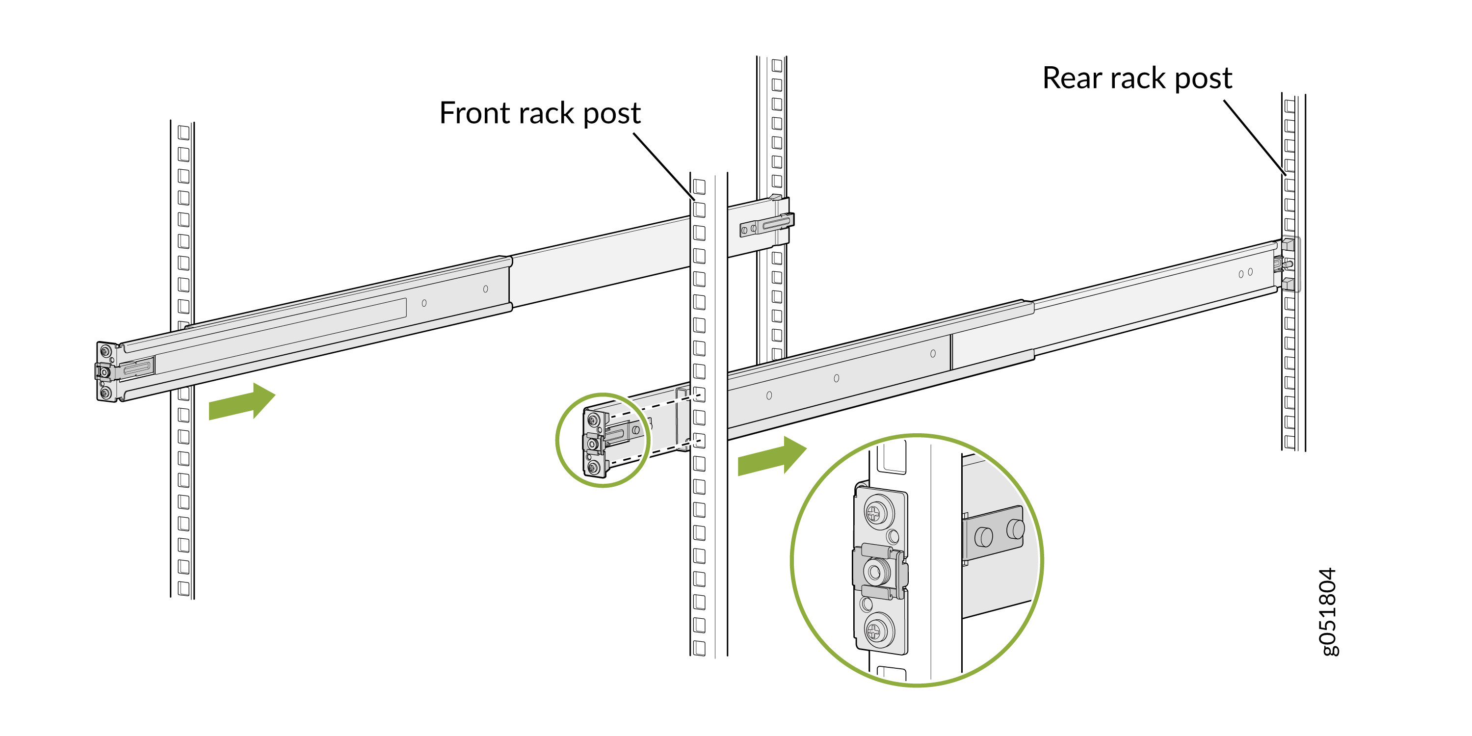 Figure 6: Both Mounting Rails Installed and Secured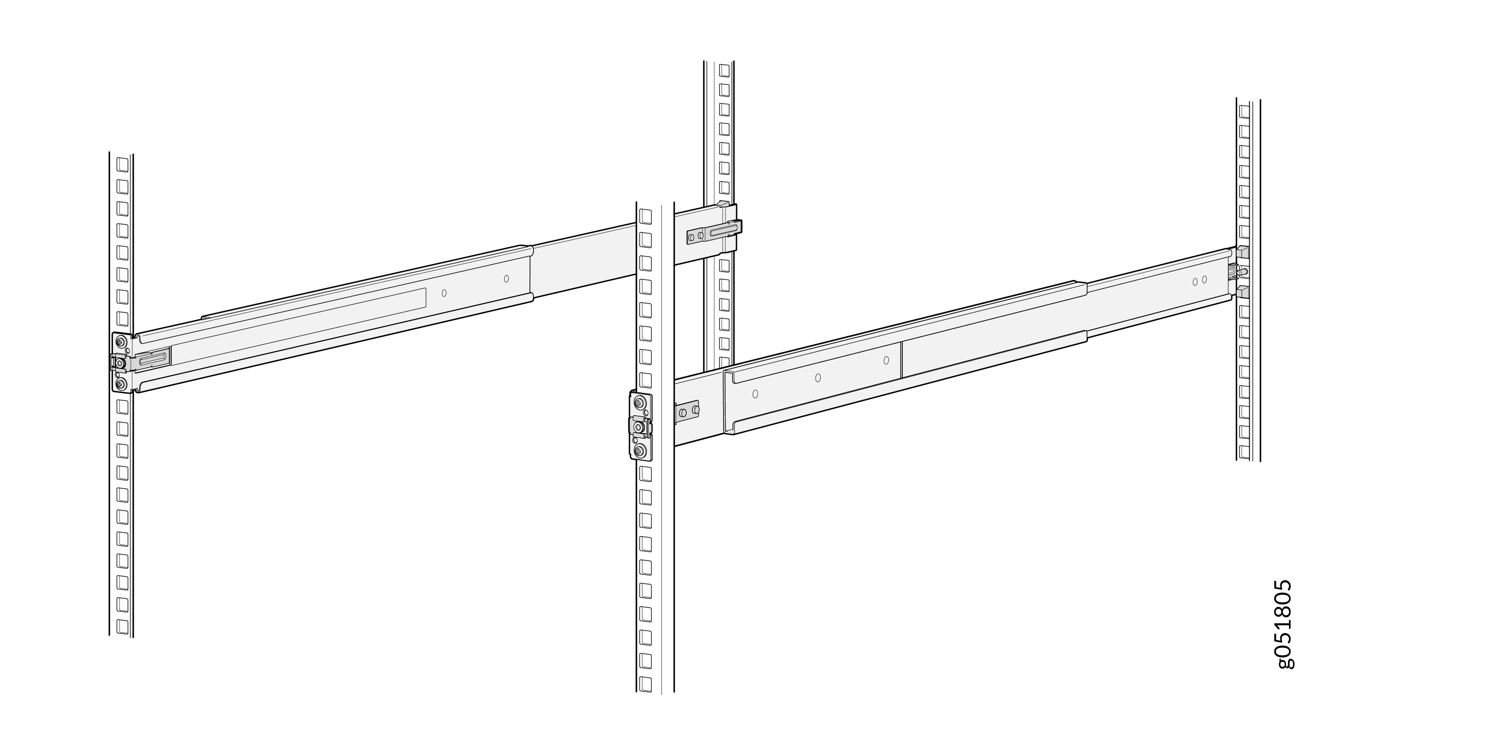
-
Use the guide pin to align the guide blocks of the rear-floating
rails with the corresponding rear post holes. Pull the rear-floating
rails toward the front of the rack to lock the rail in place. You
will hear a distinct click sound when the latch locks into the
corresponding rack holes.
-
Lift the device and position it in the rack, aligning the chassis brackets
with the mounting rails. Slide the device all the way into the channels of
the rack mounting rails.
Note:
In an AFO configuration, the chassis is installed with its front panel facing the front of the rack.
Figure 7: Slide the QFX5140 into the Rack (for AFO configuration)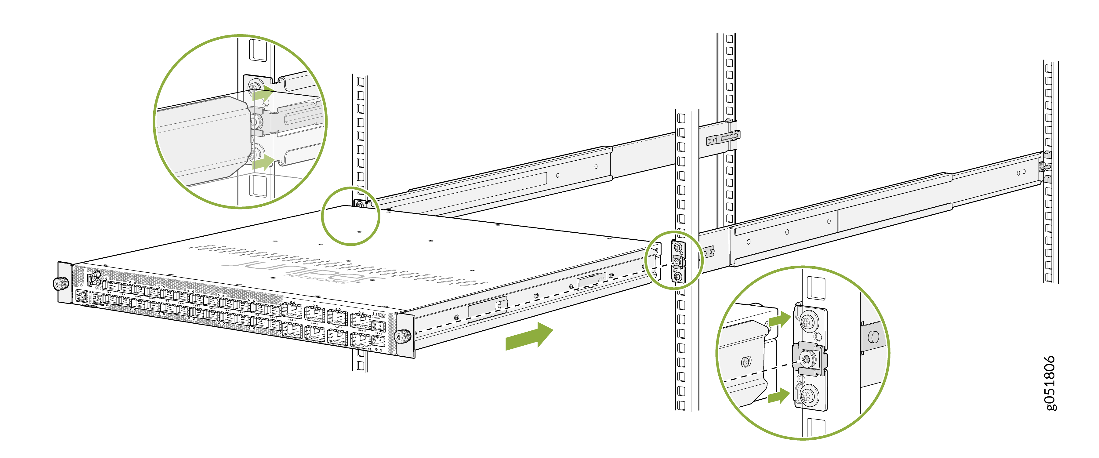 Note:
Note:In an AFI configuration, the chassis is installed with its rear panel facing the front of the rack and its front panel facing the rear. This orientation may appear unusual, but it is required for proper AFI airflow.
Figure 8: Slide the QFX5140 in the Rack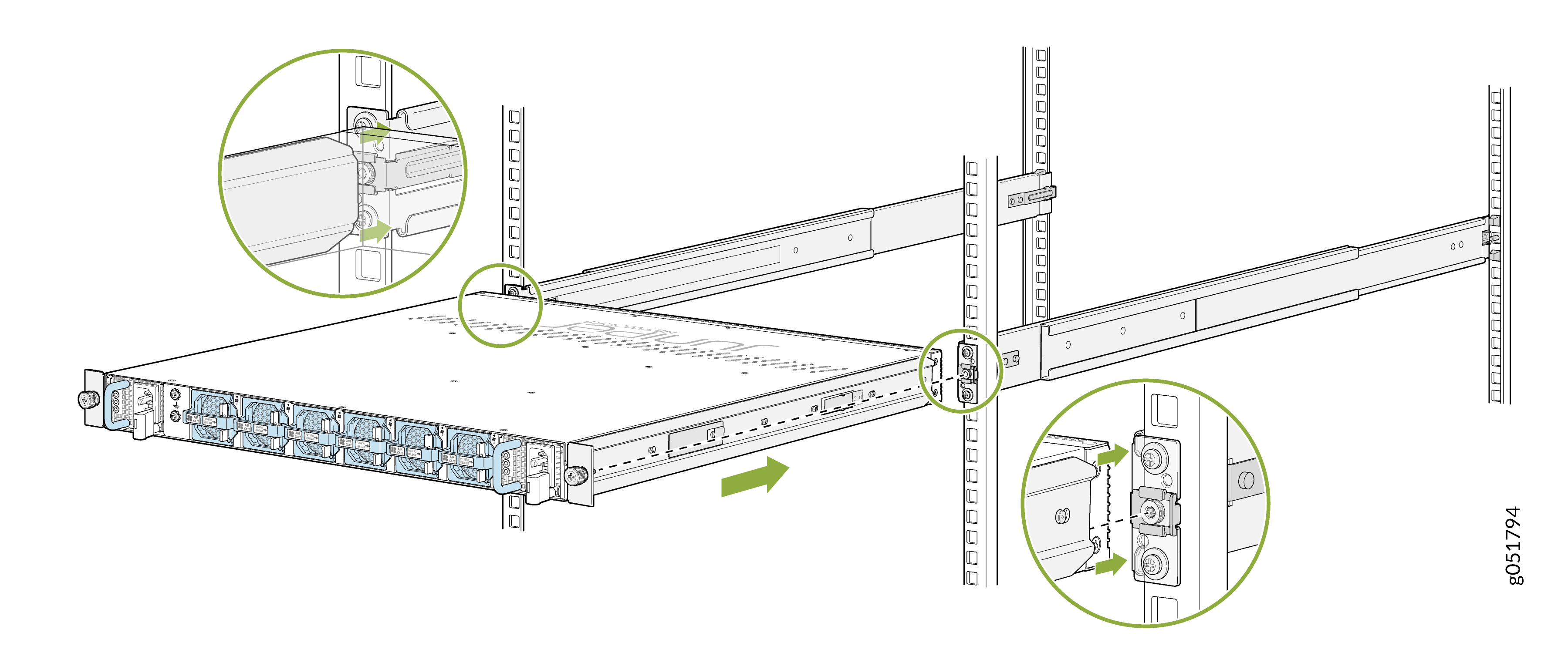
-
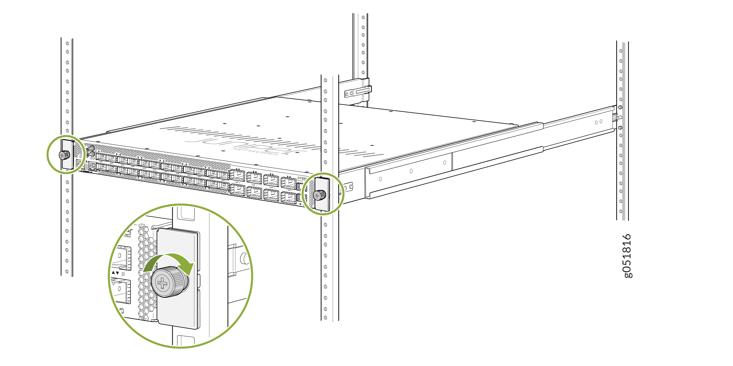
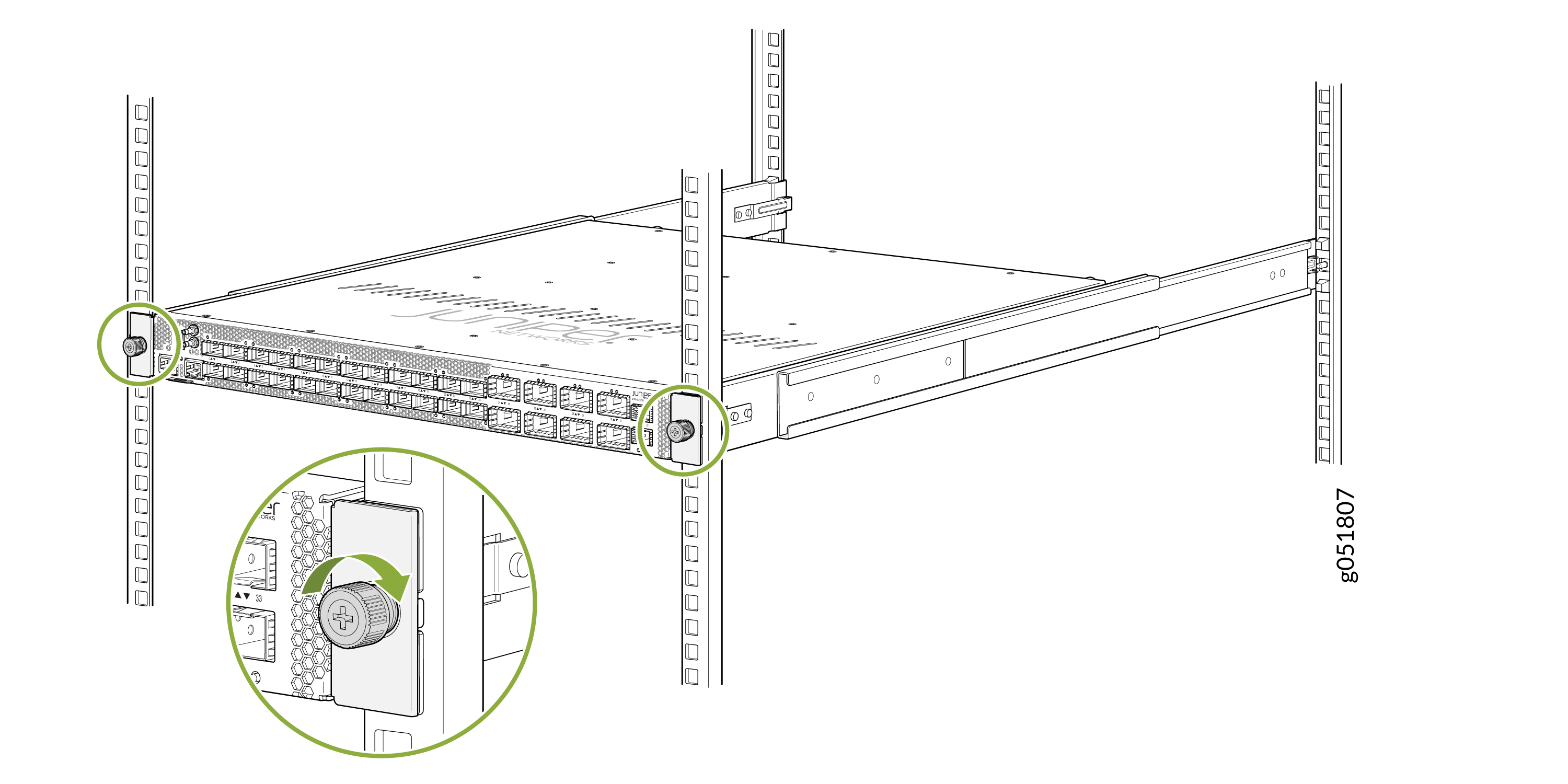
Tighten the two thumbscrews (in a clockwise direction) to secure the
device.
Figure 9: Tighten the Thumbscrews
Mount the QFX5140 on a Four-Post Round-Holed Rack Using the JNP-4P-TL-1RU RMK
Mount the QFX5140 on a four-post threaded-holed rack on your site by following the recommended procedure below.
Ensure that you have the following tools and parts available:
-
An ESD grounding strap (provided)
-
A Philips (+) screwdriver, number 2 (not provided)
-
Eight screws appropriate for your rack to attach the mounting rails to the rack posts (not provided)
-
A pair of front-mounting and rear-floating rails (provided with the RMK)
These mounting rails attach to the front and rear rack posts.
-
A pair of chassis brackets (provided with the RMK)
You must attach these brackets to the device.
Juniper provides the four-post rack mounting kit (JNP-4P-TL-1RU) with the QFX5140. If the four-post kit is lost or damaged, you can order a replacement.
To mount the QFX5140 on four posts of a threaded-hole rack using the JNP-4P-TL-1RU rack mount kit:
-
Install the chassis bracket to the chassis by aligning the keyholes on the
chassis bracket over the shoulder screws on the chassis. Slide the chassis
bracket toward the rear of the chassis.
Figure 10: Attach the Chassis Brackets
-
Assemble the mounting rails:
-
Remove the guide blocks from the front-mounting rails by loosening
the screws and washers.
Tip:
Retain the guide blocks, screws, and washers for later use.
Figure 11: Remove Guide Blocks from Front-Mounting Rail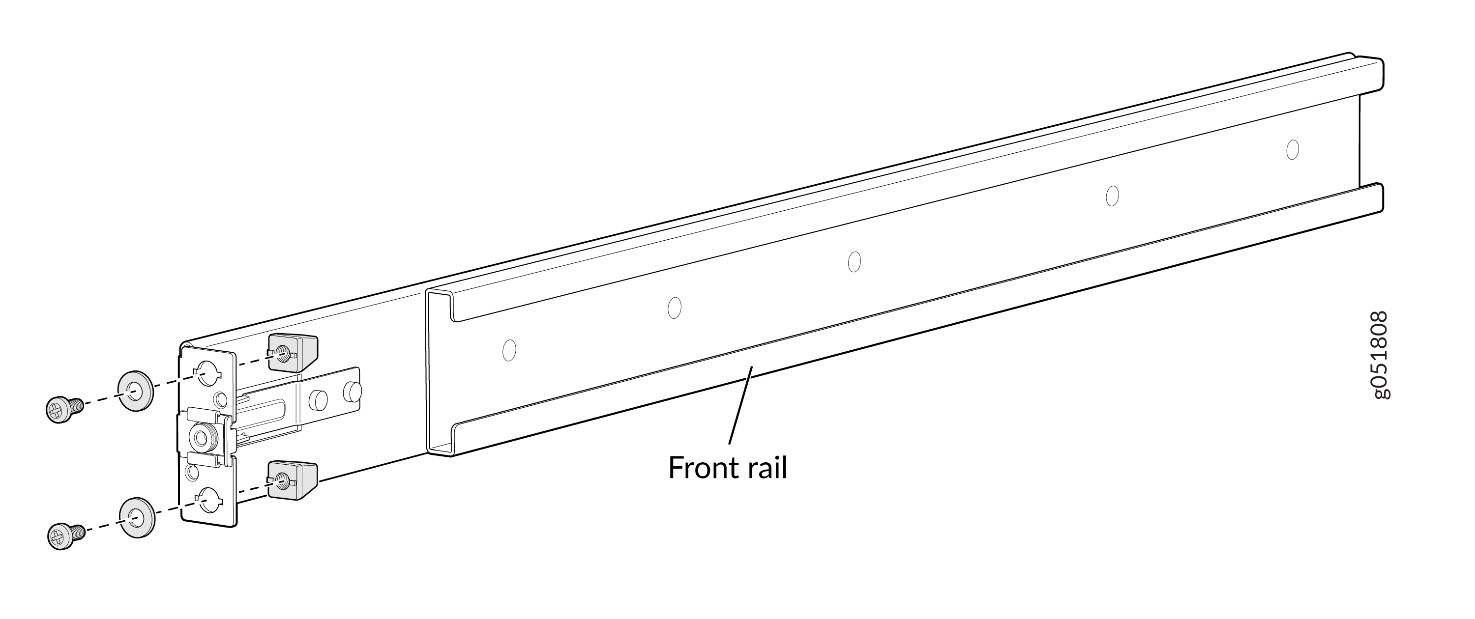
-
Remove the guide blocks from the rear-floating rails by loosening
the screws and washers.
Tip:
Retain the guide blocks, screws, and washers for later use.
Figure 12: Remove Guide Blocks from Rear-Floating Rail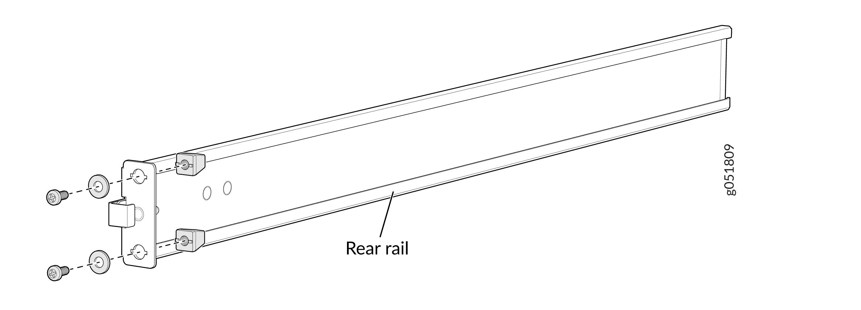
-
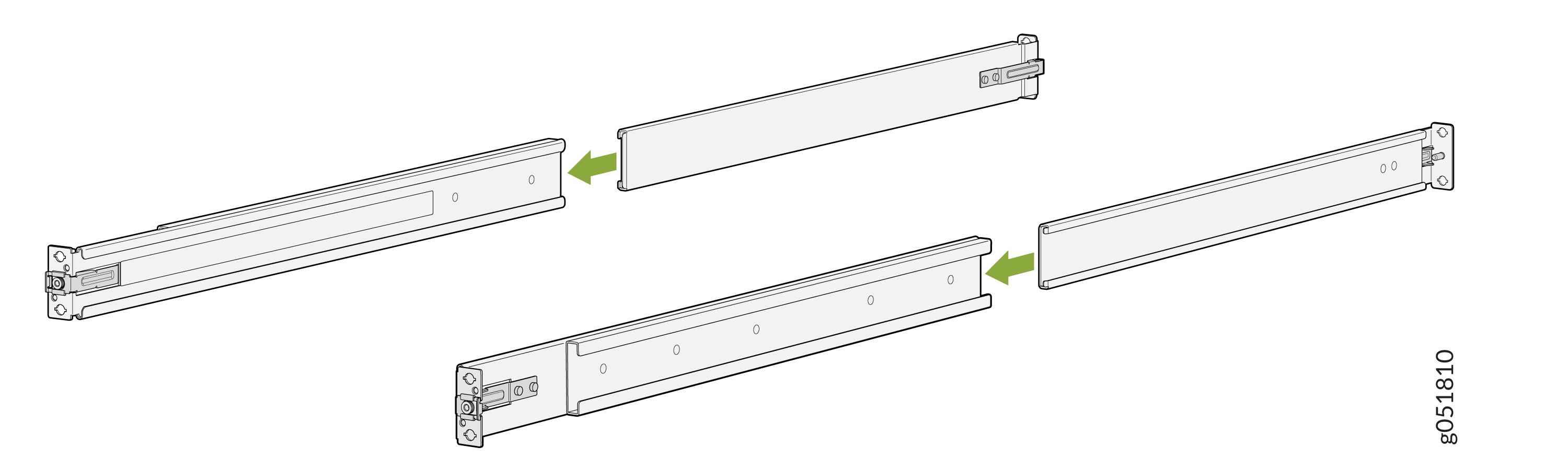
Slide the rear-floating rails into the front rails.
Figure 13: Assemble the Mounting Rails
-
Remove the guide blocks from the front-mounting rails by loosening
the screws and washers.
-
Install the mounting rails on the four-post rack:
-
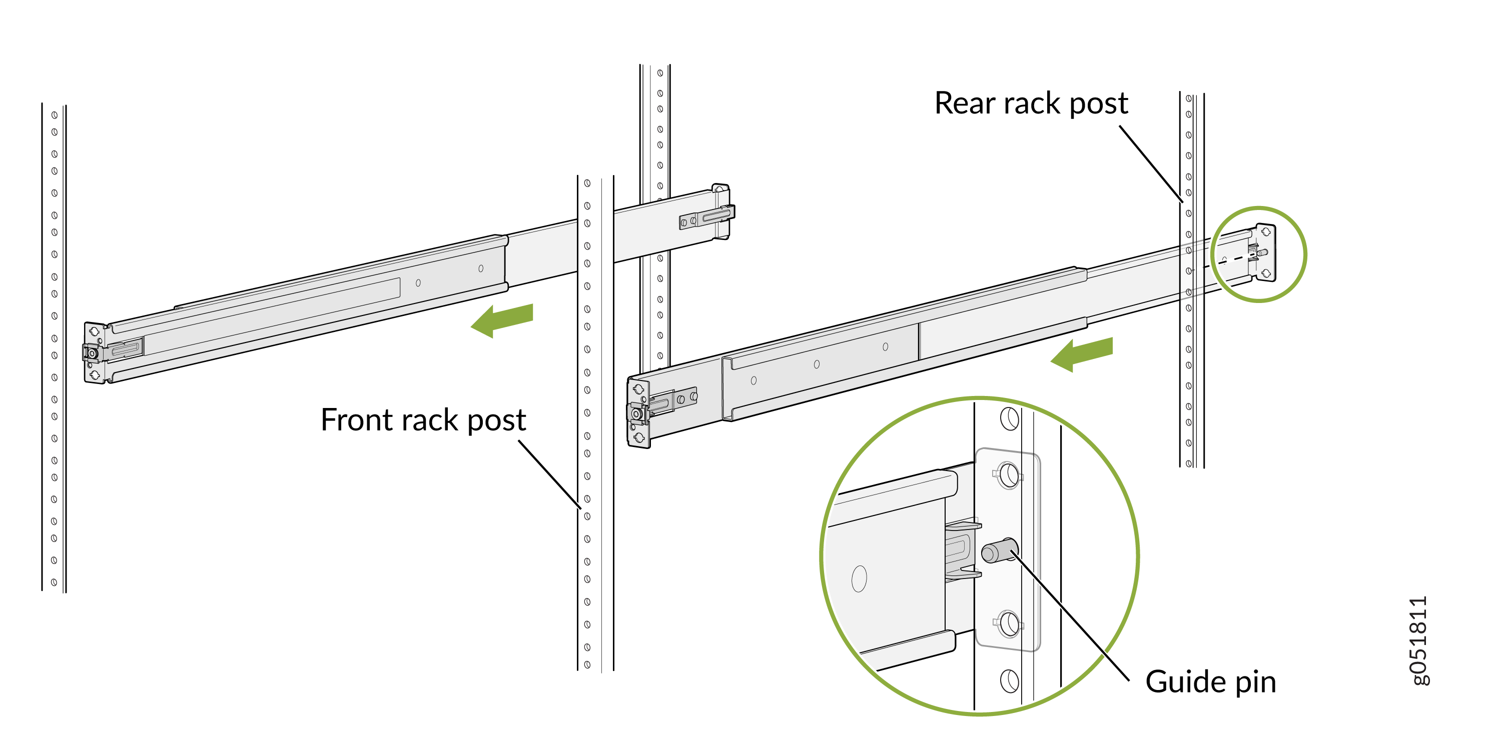
Align and insert the guide pins of the rear-floating rails into the
corresponding rear-post holes. Pull the rear-floating rails toward
the front of the rack to lock the rails in place. You will hear a
distinct click sound when each latch locks into the corresponding
rack hole.
Figure 14: Install Rear-Floating Rails
-
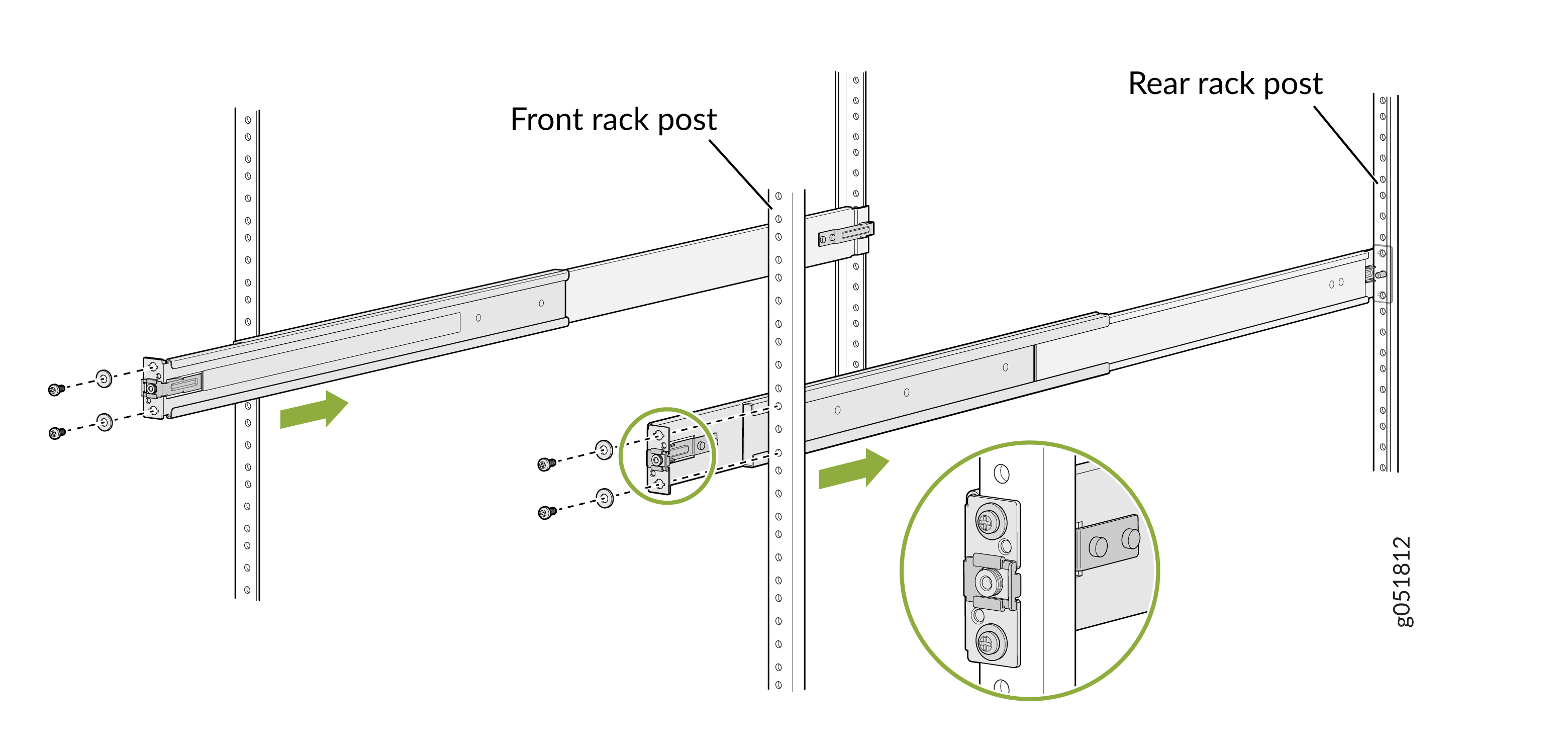
Secure the front-mounting rails to the front rack post by using
screws (not provided) appropriate for the thread size of your
rack.
Figure 15: Secure the Front-Mounting Rails
-
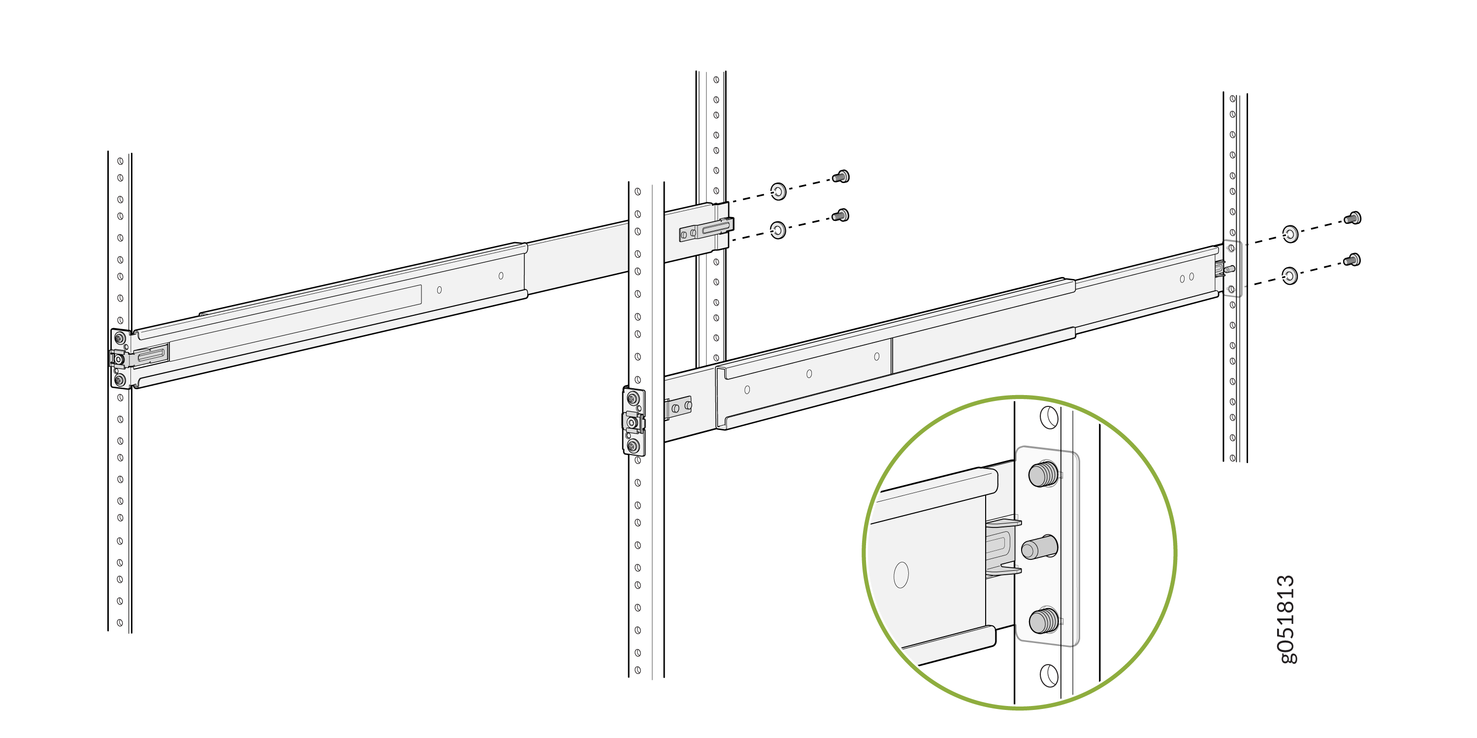
Secure the rear-floating rails to the rear rack post by using
screws (not provided) appropriate for the thread size of your
rack.
Figure 16: Secure the Rear-Floating Rails
-
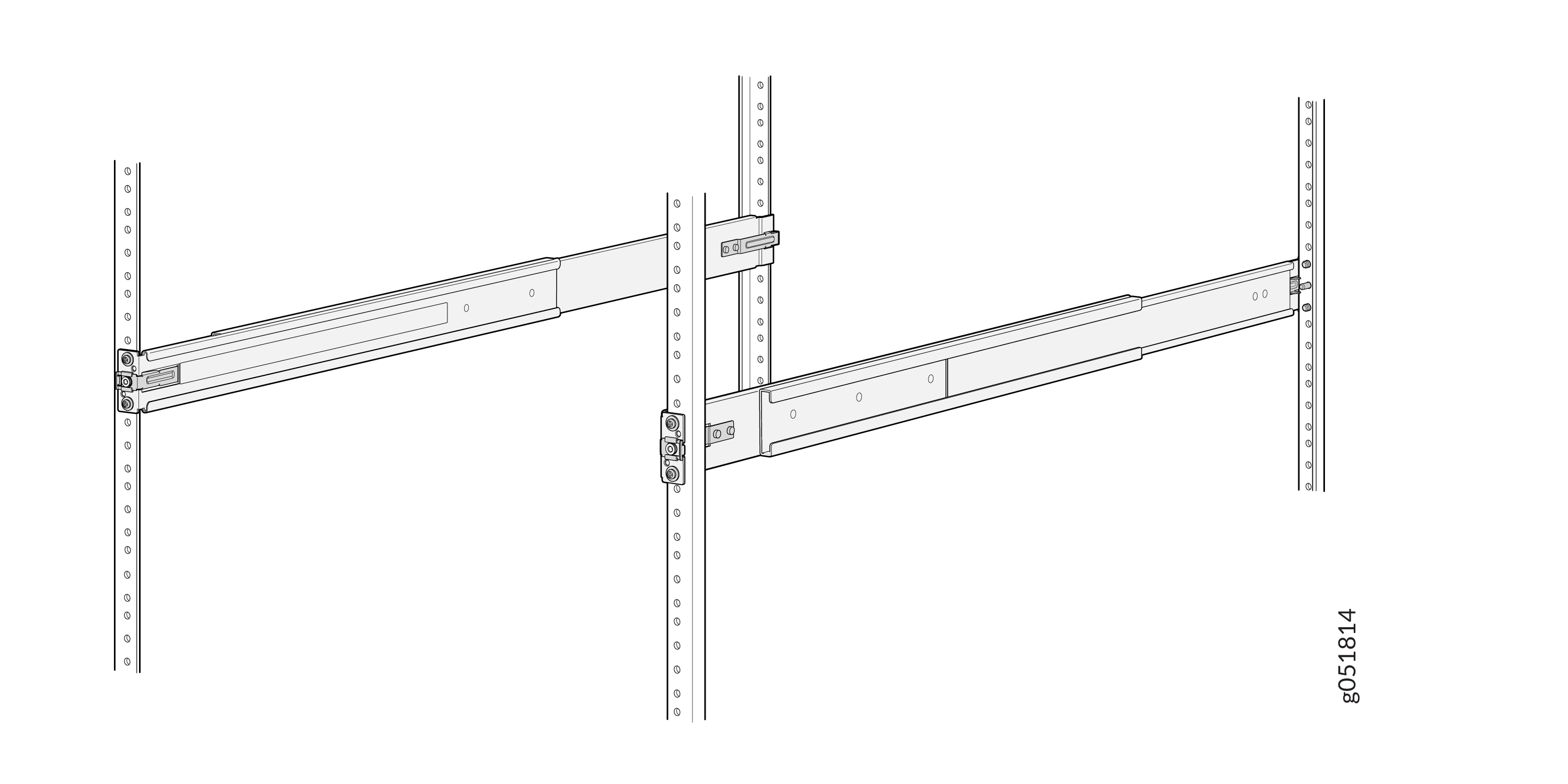
Visually confirm that you have locked the front and rear latches of
the mounting rails into the rack posts. The mounting rails should
now be securely installed on the rack.
Figure 17: Both Mounting Rails Installed and Secured
-
Align and insert the guide pins of the rear-floating rails into the
corresponding rear-post holes. Pull the rear-floating rails toward
the front of the rack to lock the rails in place. You will hear a
distinct click sound when each latch locks into the corresponding
rack hole.
-
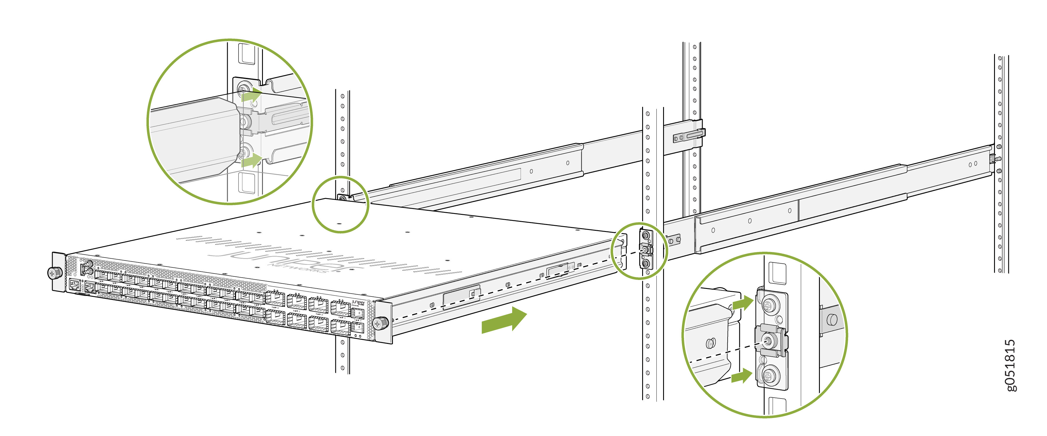
Lift the device and position it in the rack, aligning the chassis brackets
with the mounting rails. Slide the device all the way into the channels of
the mounting rails.
Figure 18: Slide the QFX5140 into the Rack
-
Tighten the two thumbscrews (in a clockwise direction) to secure the
device.
Figure 19: Tighten the Thumbscrews