QFX5130 Cooling System
QFX5130 Cooling System Description
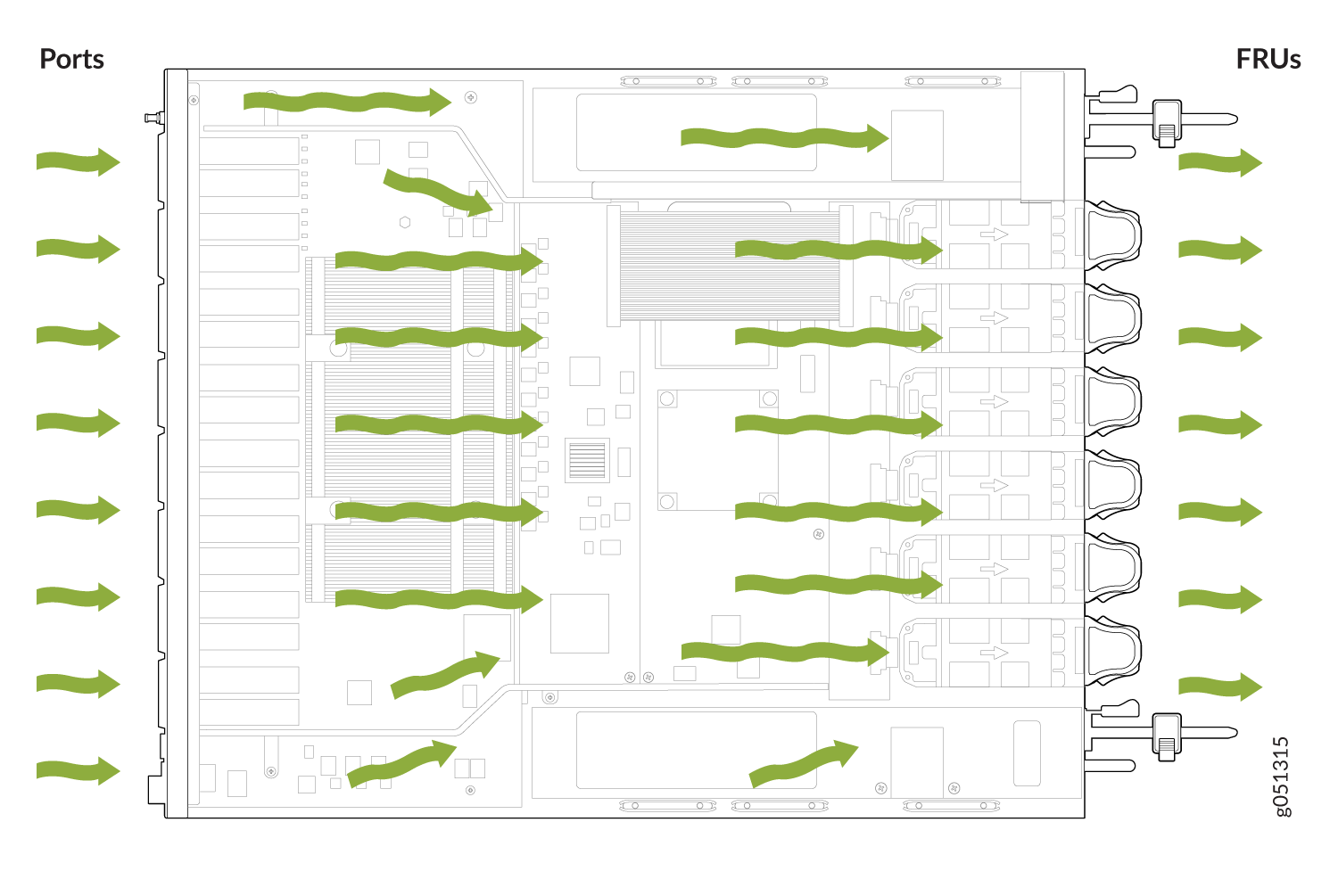
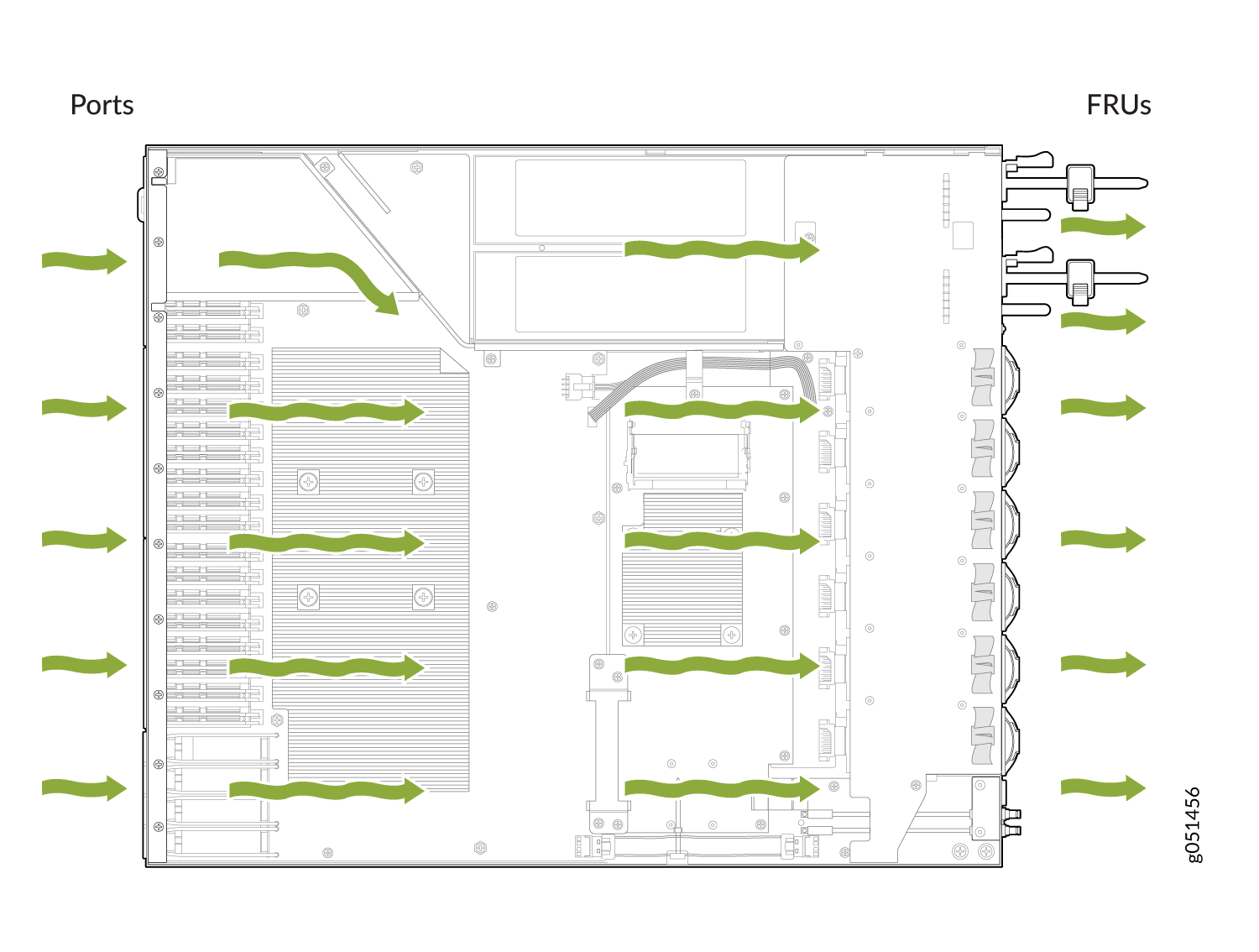
The cooling system in a QFX5130 consists of six fan modules and a single fan in each power supply. The switch can ordered in one of two airflow directions:
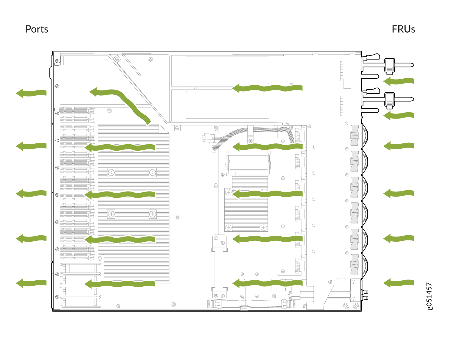
Airflow In (AFI)—Air enters the switch through the vents in the field-replaceable units (FRUs) and exhausts through the port vents.
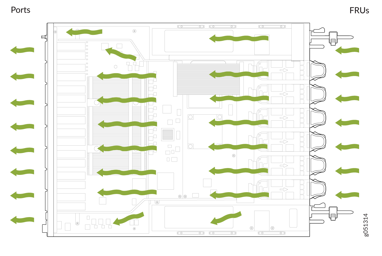
Airflow Out (AFO)—Air enters the switch through the port vents and exhausts through the vents in the FRUs.
Airflow In and Airflow Out fans and power supplies cannot be mixed in the same chassis.
Fan Modules
The fan modules in QFX5130 devices are hot-insertable and hot-removable field-replaceable units (FRUs). These fan modules are designed for one of the two available airflow directions (AFI or AFO). The fan modules are color-coded for the airflow direction as well. The fan modules are installed in the fan module slots on the FRU panel.
The QFX5130-32CD/QFX5130E-32CD and QFX5130-48C/ QFX5130-48CM cooling system consists of six fan modules numbered 0 through 5 when counting from left to right.
Figure 1 shows the fan module for QFX5130-32CD and QFX5130E-32CD.
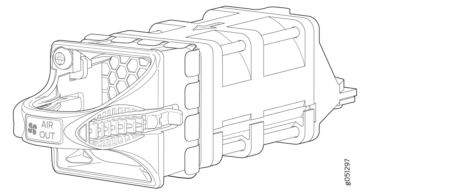
You remove and replace a fan module from the FRU end of the chassis. The QFX5130-32CD/QFX5130E-32CD switch can work with only five fans. However, we recommend that you run the switch with all six fans for redundancy and optimal switch operation. If a fan fails, or you want to run the switch without redundancy, leave the sixth fan in place to maintain proper airflow. When you replace a fan, the switch continues to operate for a limited period of time (3 minutes) without thermal alarms or shutdown.
Figure 2 shows the fan module for QFX5130-48C/QFX5130-48CM.
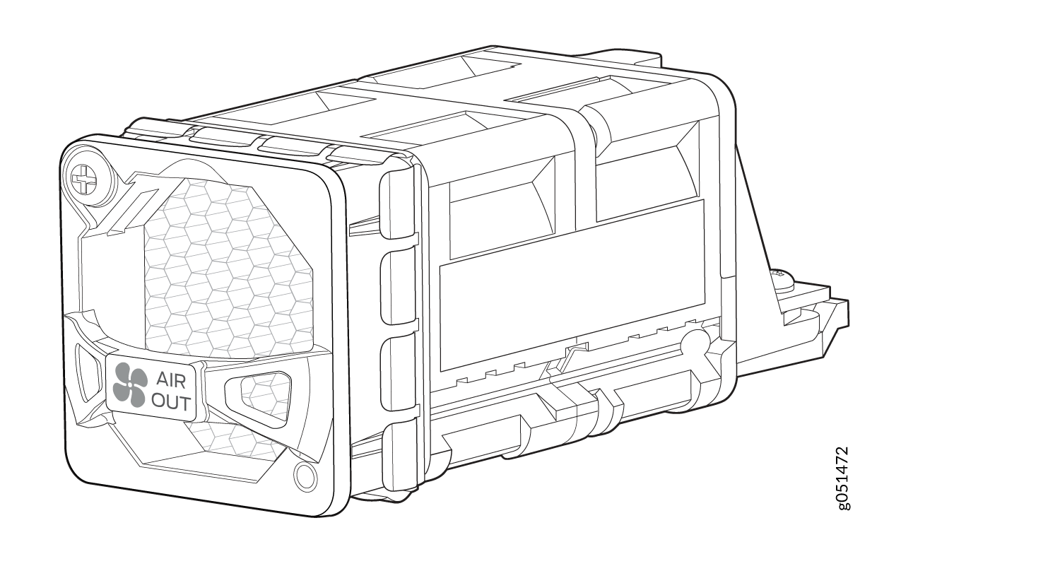
You can remove and replace a fan module from the FRU end of the chassis. The QFX5130-48C switch cannot work with only five fans as the redundancy for this switch is supported only at the rotor level. We recommend that you run the device with all six fans for redundancy and optimal switch operation. If a fan rotor fails, or if you want to run the switch without redundancy, you would need to leave the sixth fan in place to maintain proper airflow. When you replace a fan when the switch is running, the switch continues to operate for a limited period of time (240 seconds) without thermal alarms or shutdown.
The fan modules are available in two product variants that have different airflow directions—FRU-to-port airflow and port-to-FRU airflow. Table 1 lists the available fan module product variants and the direction of airflow in them:
Fan Module |
Airflow Diagram |
Label on the Fan Module |
Color of Fan Module |
Direction of Airflow in the Fan Module |
Power Supplies |
|---|---|---|---|---|---|
QFX5130-32CD-FANAI/QFX5130E-32CD-FANAI |
AIR IN |
Juniper azure blue |
FRU-to-port, that is, air comes in from the end of the switch with the fans; air exhausts from the switch end with ports (also known as back-to-front airflow). |
You must install only those power supplies that have AIR IN labels in switches in which the fan modules have AIR IN labels. |
|
QFX5130-32CD-FANAO/QFX5130E-32CD-FANAO |
AIR OUT |
Juniper gold |
Port-to-FRU, that is, air comes in through vents on the end with ports; air exhausts out the end with the fans (also known as front-to-back airflow). |
You must install only power supplies that have AIR OUT labels in switches in which the fan modules have AIR OUT labels. |
|
| QFX5130-48C-FANAFI | Figure 4 | AIR IN |
Juniper azure blue |
FRU-to-port, that is, air comes in from the end of the switch with the fans; air exhausts from the switch end with ports (also known as back-to-front airflow). |
You must install only power supplies that have AIR IN labels in switches in which the fan modules have AIR IN labels. |
| QFX5130-48C-FANAFO | Figure 6 | AIR OUT |
Juniper gold |
Port-to-FRU, that is, air comes in through vents on the end with ports; air exhausts out the end with the fans (also known as front-to-back airflow). |
You must install only power supplies that have AIR OUT labels in switches in which the fan modules have AIR OUT labels. |
In data center deployments, position the switch in such a manner that the AIR IN labels on switch components are next to the cold aisle and AIR OUT labels on the switch components are next to the hot aisle.
Do Not Install Components with Different Airflow or Wattage in the Switch
Do not mix airflow direction on fans or power supplies. You can use the color-coding on fan and power supply handles to ensure that the airflow direction matches. The handles on AFI fans and power supplies are azure blue, compared to the AFO fans and power supplies, which are Juniper gold.
Mixing components with different airflows in the same chassis hampers the performance of the cooling system of the switch and leads to overheating of the chassis.
The system raises an alarm if a fan module fails or if the ambient temperature inside the chassis rises above the acceptable range. If the temperature inside the chassis rises above the threshold temperature, the system shuts down automatically. The system takes 3 minutes (for QFX5130-32CD/QFX5130E-32CD) or 240 seconds (for QFX5130-48C/QFX5130-48CM) to shut down after the red alarm threshold is reached.
Do not mix fan modules with different wattage. Use only the replacement fan modules that are designed for use with your product number. See Table 1 for the correct part number for your QFX5130 switch.
Do not mix AC and DC power supplies in the same QFX5130 chassis.
However, if you need to convert a QFX5130 switch to have a different airflow, you can change the airflow pattern. To convert an AIR IN product variant to an AIR OUT product variant or an AIR OUT product variant to an AIR IN product variant, you must power off and replace all of the fans and power supplies at one time to use the new airflow direction. The system raises an alarm when the system is converted, which is normal.
If you change the switch to have a different airflow, be sure to update your JTAC install base to reflect the new configuration to ensure that service warranties and contracts remain˙.
QFX5130 Fan Module LED
On the QFX5130-32CD/QFX5130E-32CD switches, the fan module LEDs are located on the chassis, next to the fan module slot. On the QFX5130-48C switches, the fan module LEDs are located on the fan module. Figure 7 shows the location of fan module LEDs next to the fan module on a QFX5130-32CD/QFX5130E-32CD switch.Figure 8 shows the location of fan module LEDs on a QFX5130-48C switch.
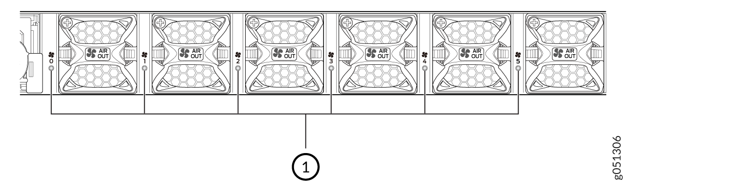
1 — Fan module LED |
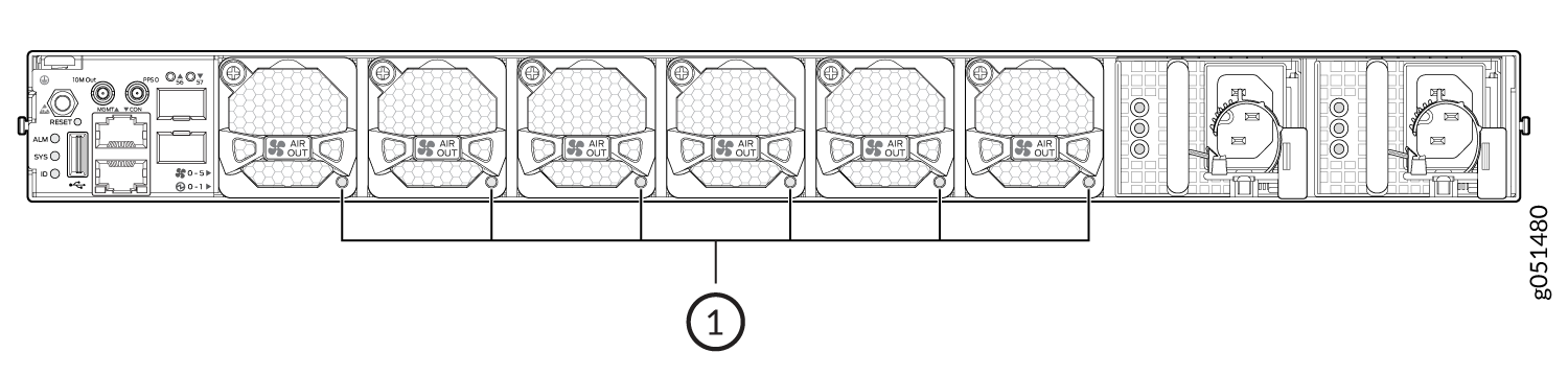
1 — Fan module LED |
The fans are numbered 0 through 5, starting from the fan closest to the ports.
Table 2 describes the function of the fan tray LED.
Name |
Color |
State |
Description |
|---|---|---|---|
Fan |
Green |
On steadily |
The fan module is operating normally. The system has verified that the module is engaged, that the airflow is in the correct direction, and that the fan is operating correctly.
|
Amber (QFX5130-32CD/QFX5130E-32CD) |
Blinking |
An error has been detected in the fan module. Replace the fan module as soon as possible. Either the fan has failed or it is seated incorrectly. To maintain proper airflow through the chassis, leave the fan module installed in the chassis until you are ready to replace it. |
|
| Amber (QFX5130-48C | On steadily |
Indicates one of the following conditions:
|
Under normal operating conditions, the fan modules operate at a moderate speed. Temperature sensors in the chassis monitor the temperature within the chassis.
The system raises an alarm if a fan module fails or if the ambient temperature inside the chassis rises above the acceptable range. If the temperature inside the chassis rises above the threshold temperature, the system shuts down automatically.
Fan Module Status
show chassis temperature-thresholds, show system alarm, or show chassis environment commands, or by looking at the LEDs next to each fan module. On the QFX5130-48C switches, the LED is located on the fan module. For example:user@device> show chassis fan Item Status % RPM Measurement Fan Tray 0 Fan 1 Ok 38% 11400 RPM Fan Tray 0 Fan 2 Ok 37% 12150 RPM Fan Tray 1 Fan 1 Ok 39% 11550 RPM Fan Tray 1 Fan 2 Ok 37% 12150 RPM Fan Tray 2 Fan 1 Ok 39% 11550 RPM Fan Tray 2 Fan 2 Ok 37% 12150 RPM Fan Tray 3 Fan 1 Ok 38% 11250 RPM Fan Tray 3 Fan 2 Ok 36% 12000 RPM Fan Tray 4 Fan 1 Ok 38% 11400 RPM Fan Tray 4 Fan 2 Ok 37% 12150 RPM Fan Tray 5 Fan 1 Ok 38% 11400 RPM Fan Tray 5 Fan 2 Ok 36% 12000 RPM
user@device> show chassis environment
Class Item                           Status     Measurement
Temp  PSM 0                          Ok         25 degrees C / 77 degrees F

      PSM 1                          Ok         24 degrees C / 75 degrees F

      FPC 0 Sensor TopMiddle         Ok         29 degrees C / 84 degrees F

      FPC 0 Sensor TopFrontLeft      Ok         24 degrees C / 75 degrees F

      FPC 0 Sensor TopBack           Ok         32 degrees C / 89 degrees F

      FPC 0 Sensor BottomBack        Ok         32 degrees C / 89 degrees F

      FPC 0 Sensor CPUTopLeft        Ok         29 degrees C / 84 degrees F

      FPC 0 Sensor CPUBottomMiddle   Ok         35 degrees C / 95 degrees F

      FPC 0 Sensor CPUTopBackRight   Ok         29 degrees C / 84 degrees F

      FPC 0 Sensor TD4 Max Reading   Ok         50 degrees C / 122 degrees F

      Routing Engine 0 CPU Temperature Ok       45 degrees C / 113 degrees F

Fan   Fan Tray 0 Fan 1               Ok         13000 RPM

      Fan Tray 0 Fan 2               Ok         11800 RPM

      Fan Tray 1 Fan 1               Ok         12800 RPM

      Fan Tray 1 Fan 2               Ok         11900 RPM

      Fan Tray 2 Fan 1               Ok         13000 RPM

      Fan Tray 2 Fan 2               Ok         11800 RPM

      Fan Tray 3 Fan 1               Ok         13000 RPM

      Fan Tray 3 Fan 2               Ok         11800 RPM

      Fan Tray 4 Fan 1               Ok         12800 RPM

      Fan Tray 4 Fan 2               Ok         11700 RPM

      Fan Tray 5 Fan 1               Ok         12700 RPM

      Fan Tray 5 Fan 2               Ok         11800 RPM
The QFX5130 switch has a status LED (labeled ST) for each fan module. The LED indicates the status of all the fan modules.