Fast Track to Rack Installation and Power
This procedure walks you through the most basic steps for installing your QFX5130 switch in a rack and connecting it to power.
Install the QFX5130-32CD/QFX5130E-32CD Switch in a Rack
You can install the QFX5130-32CD/QFX5130E-32CD switch in a four-post rack or cabinet. We’ll walk you through the steps to install an AC-powered switch in a square-hole four-post rack.
Before you install the switch, review:
To mount the device on four posts in a rack by using the QFX5K-4PST-RMK-E rack mount kit (RMK):
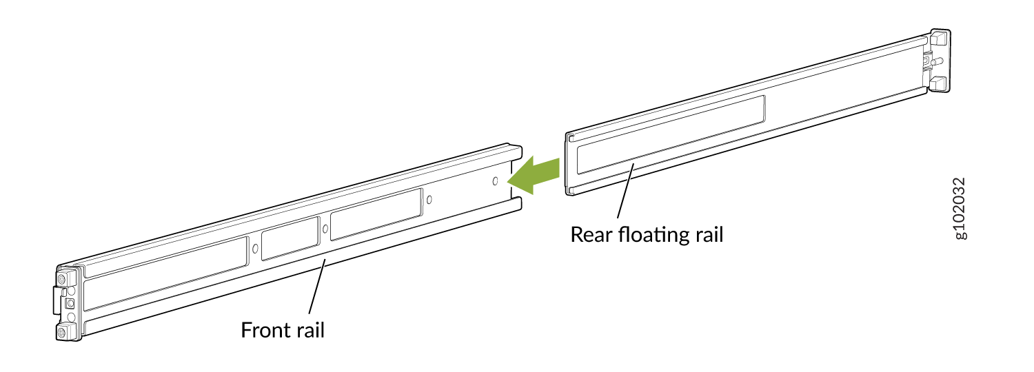
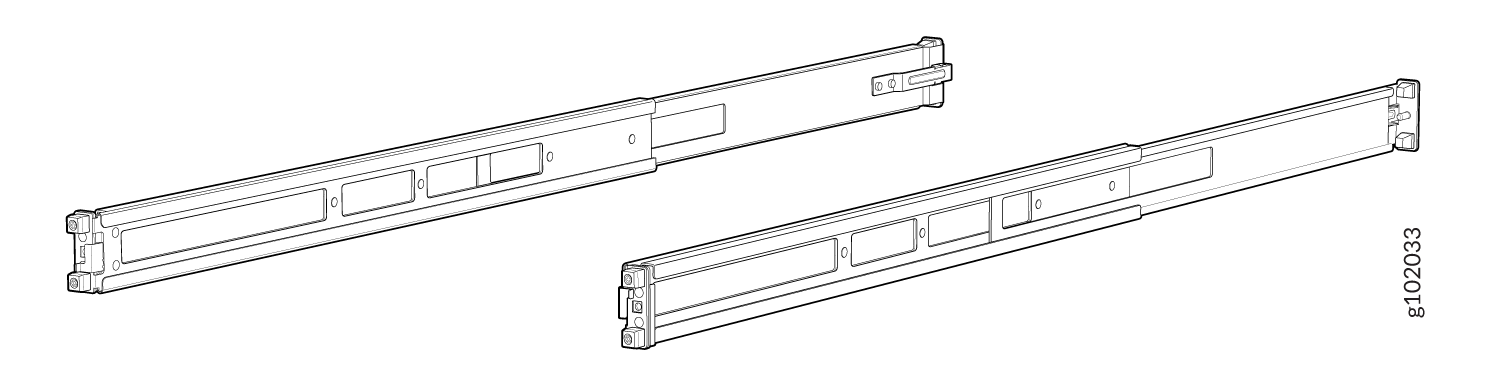
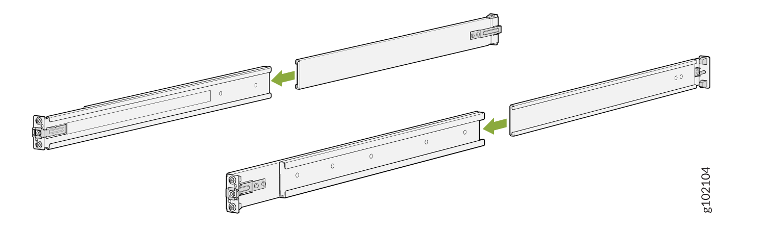
- Assemble the mounting rails.
- Attach the mounting rails to the rack.
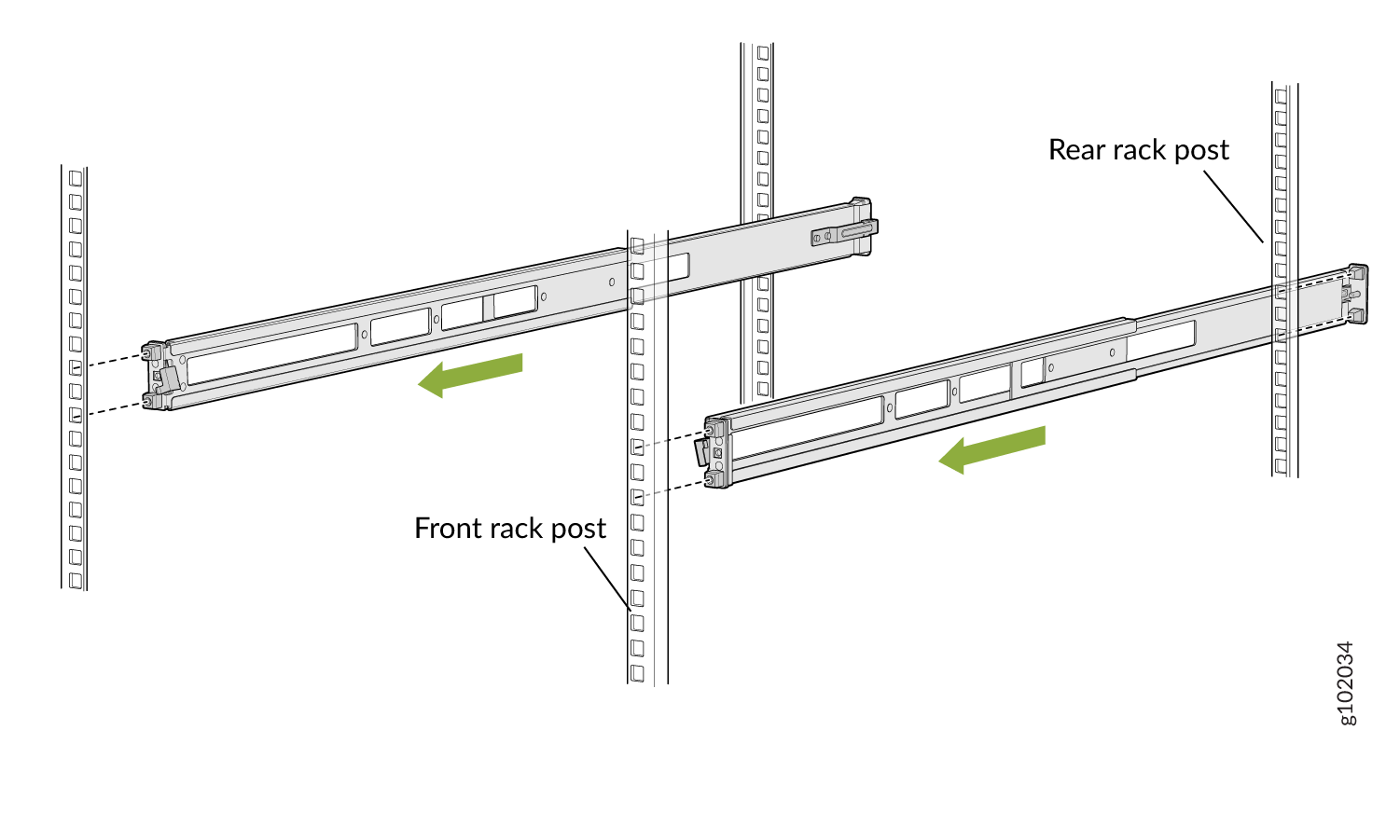
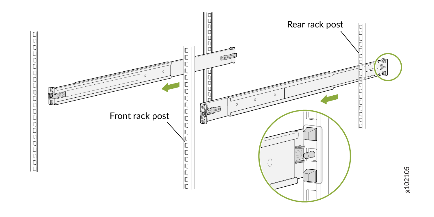
- Standing in front of the rack, align the guide blocks of the rear mounting rails with the rear-post holes. Pull the rear mounting rails toward the front of the rack to lock the rails in place. You will hear a click sound when the latch locks into the corresponding rack holes. See Figure 3.Figure 3: Install the Rear-Floating Rails
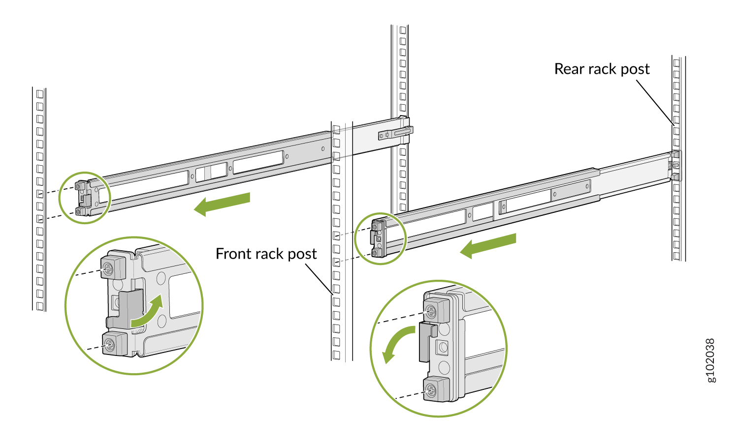
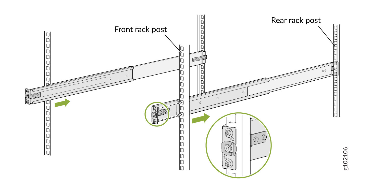
- Move the latch lock on the front mounting rail to open position, slide the front mounting rail, and insert the guide blocks into the front rack posts. See Figure 4.Figure 4: Install the Front Mounting Rails
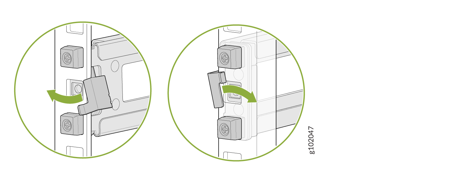
- Push the lock latch to the locked position. See Figure 5.Figure 5: Front Mounting Rail's Lock Latch
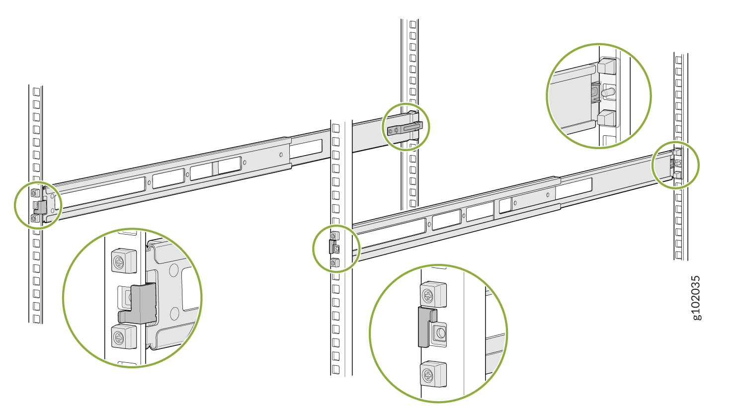
- Visually ensure that the front and rear latches are locked into place on the mounting rails. See Figure 6.Figure 6: Mounting Rails Installed and Locked
- Standing in front of the rack, align the guide blocks of the rear mounting rails with the rear-post holes. Pull the rear mounting rails toward the front of the rack to lock the rails in place. You will hear a click sound when the latch locks into the corresponding rack holes. See Figure 3.
- Attach the spacers and the mounting brackets to the device if not preinstalled. If your device has the spacers and mounting brackets preinstalled, then skip this step and move to the next step.
- Insert the flat head M4 x 6mm Phillips screws to attach the spacer and the mounting bracket into the aligned holes on the chassis (see Figure 7). Tighten the screws.Figure 7: Attach the Spacers And the Mounting Brackets to the Device
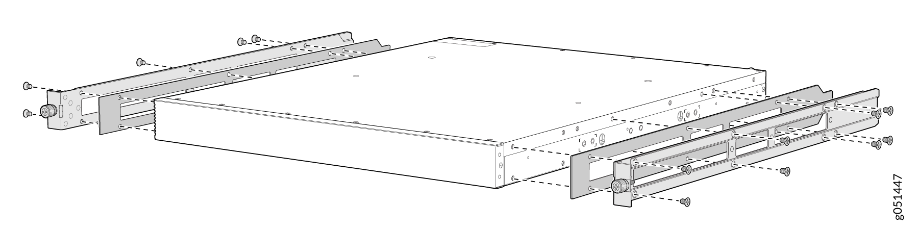
- Insert the flat head M4 x 6mm Phillips screws to attach the spacer and the mounting bracket into the aligned holes on the chassis (see Figure 7). Tighten the screws.
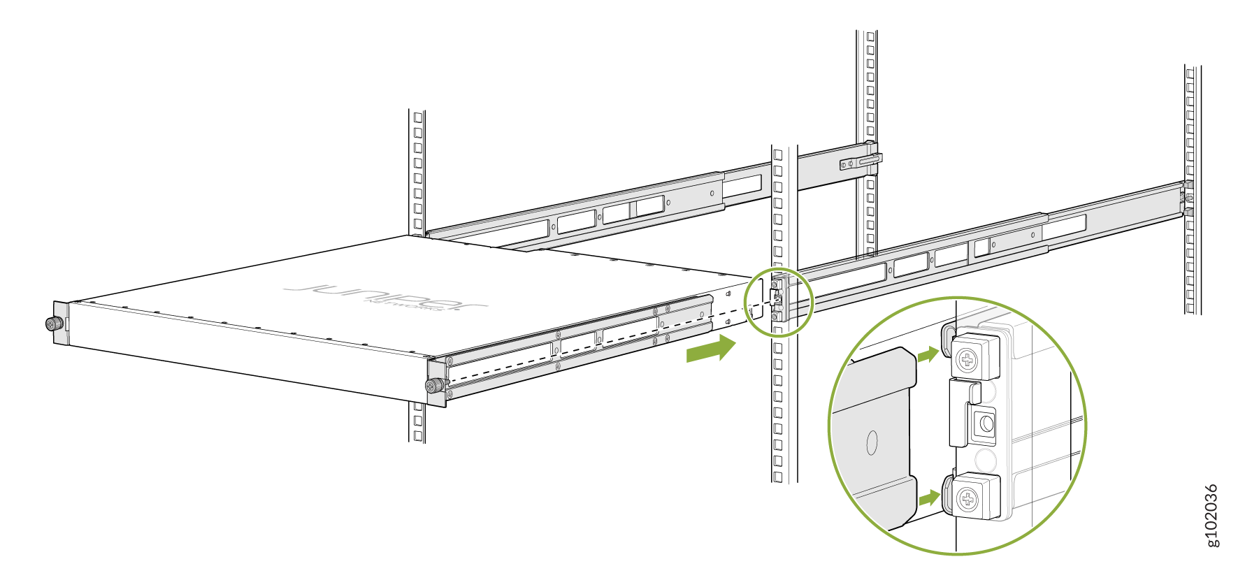
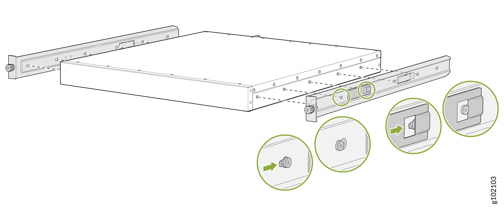
- Lift the device and position it in the rack, aligning the side mounting brackets with the mounting rails. Slide the device into the channels of the rack mounting rails. See Figure 8.Figure 8: Slide the Device into the Rack
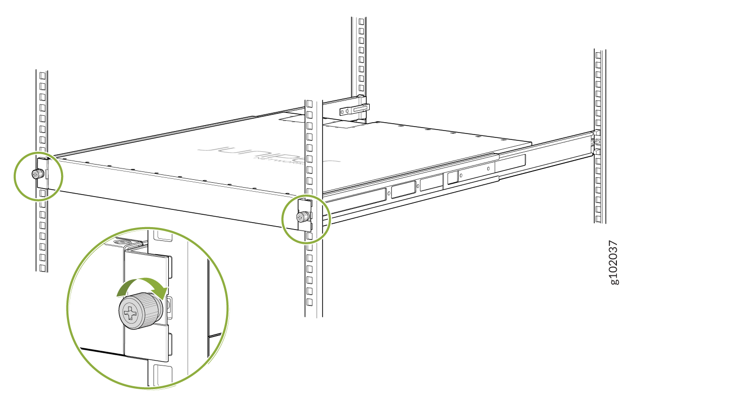
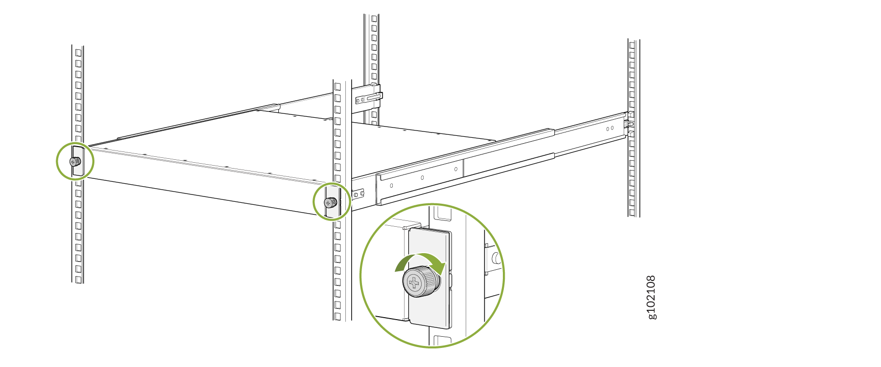
- Tighten the two thumbscrews to secure the device. See Figure 9.Figure 9: Tighten Thumb Screws
Connect to Power
- Ground the QFX5130-32CD/QFX5130E-32CD Switch
- Connect the Power Cord and Power On the QFX5130-32CD/QFX5130E-32CD Switch
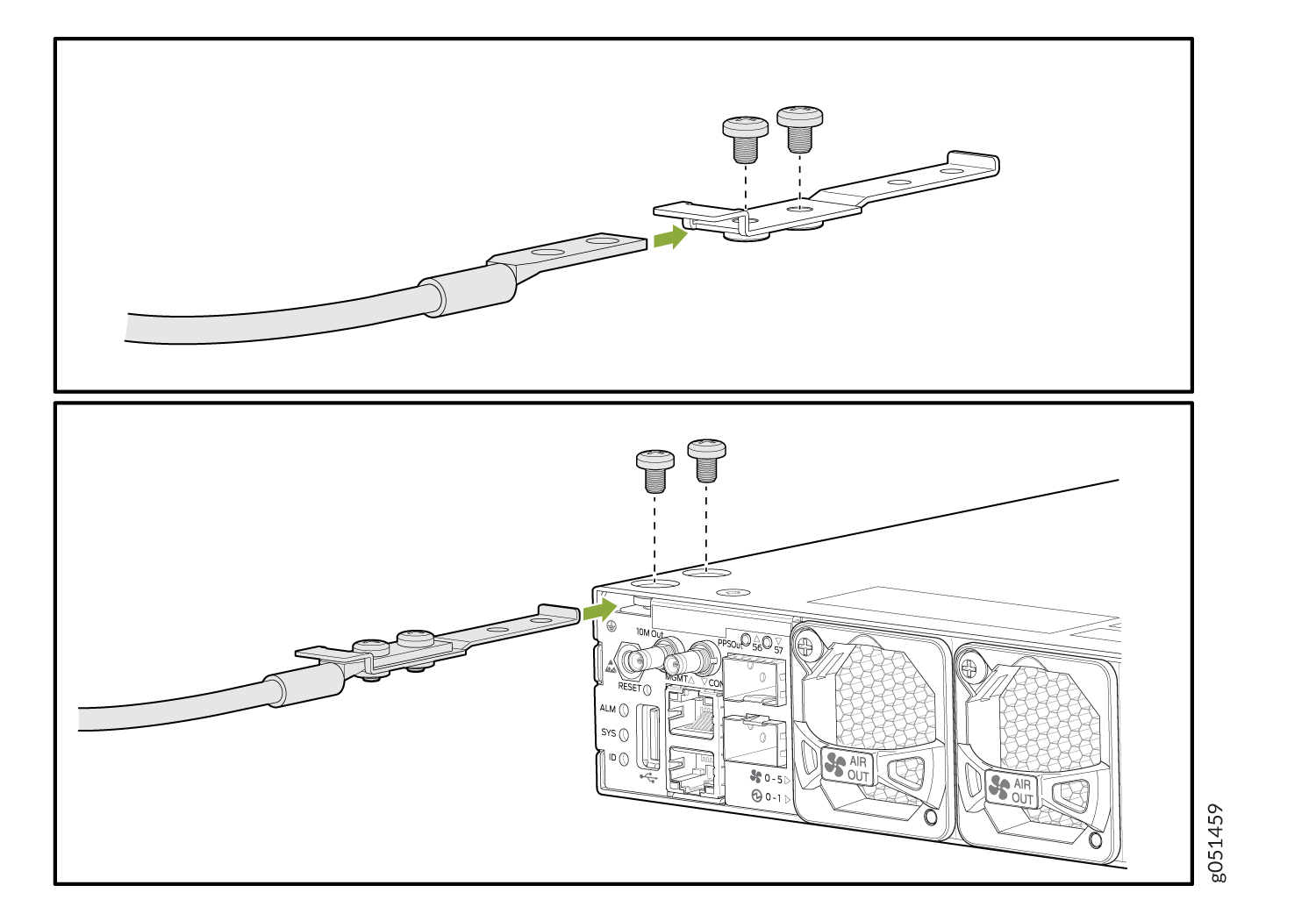
Ground the QFX5130-32CD/QFX5130E-32CD Switch
To ground the QFX5130-32CD/QFX5130E-32CD switch:
Wrap and fasten one end of the electrostatic discharge (ESD) cable grounding strap around your bare wrist, and connect the other end to a site ESD point.
Connect the grounding cable to a proper earth ground, such as the rack in which you mount the device.
Place the grounding cable terminal attached to the grounding cable over the grounding point.
Secure the grounding cable terminal to the grounding point using the M5 screws.
Figure 10: Ground the QFX5130-32CD/QFX5130E-32CD Switch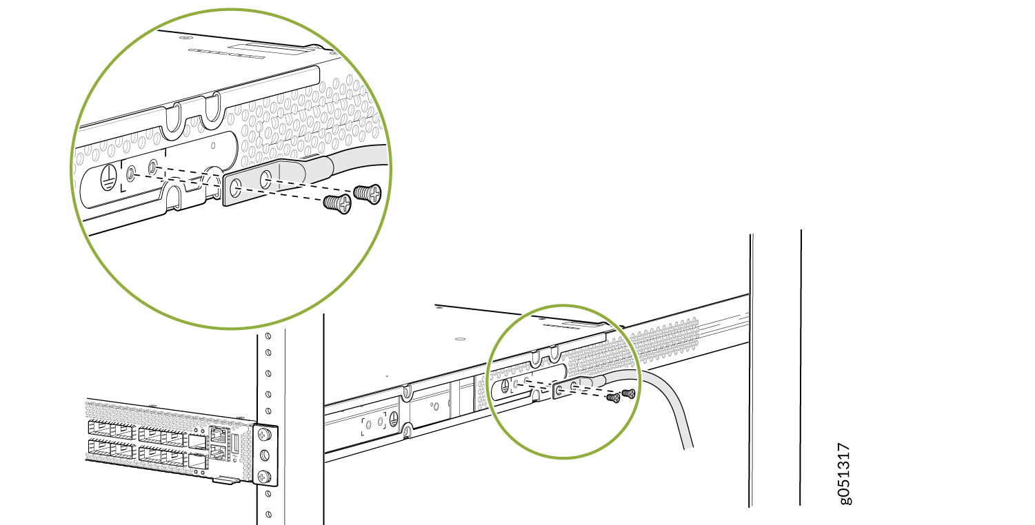
Dress the grounding cable. Ensure that the cable doesn’t block access to or come in contact with other device components, and that it doesn’t drape where people could trip on it.
Connect the Power Cord and Power On the QFX5130-32CD/QFX5130E-32CD Switch
For information about the supported AC power cord specifications, see AC Power Cord with Type C15 Coupler Specifications.
To connect the power cord:
Ensure that the power supply is fully inserted in the rear panel of the switch.
Insert the coupler end of the power cord into the AC power cord socket on the rear panel.
Push the power cord retainer on to the power cord.
Figure 11: Connect the Power Cord to a QFX5130-32CD/QFX5130E-32CD Switch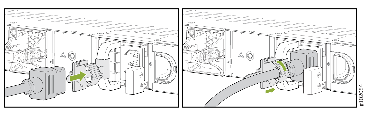
If the AC power source outlet has a power switch, turn it off.
Plug the power cord into an AC power source outlet.
If the AC power source outlet has a power switch, turn it on. If the AC power source outlet doesn't have a power switch, it powers on as soon as you plug it in.
Install the QFX5130-48C/QFX5130-48CM Switch in a Rack
Before you install, review:
- Attach the side-mounting brackets to the chassis. Align the keyholes of the mounting brackets over the shoulder screws of the chassis. Slide the mounting brackets toward the rear of the chassis.
- Assemble the mounting rails by sliding the rear rails into the front rails.
- Align the guide blocks of the rear-mounting rail with the rear-post holes. Pull the rear-mounting rail toward the front of the rack to lock the rail in place. You'll hear a distinct click when the latch locks into the rack holes.
- Align the guide blocks of the front-mounting rail with the front-post holes. Push the front-mounting rail toward the rear of the rack to lock the rail in place. You'll hear a distinct click when the latch locks into the rack holes.
- Lift the device and position it in the rack, aligning the side-mounting brackets with the mounting rails. Slide the device into the channels of the mounting rails.
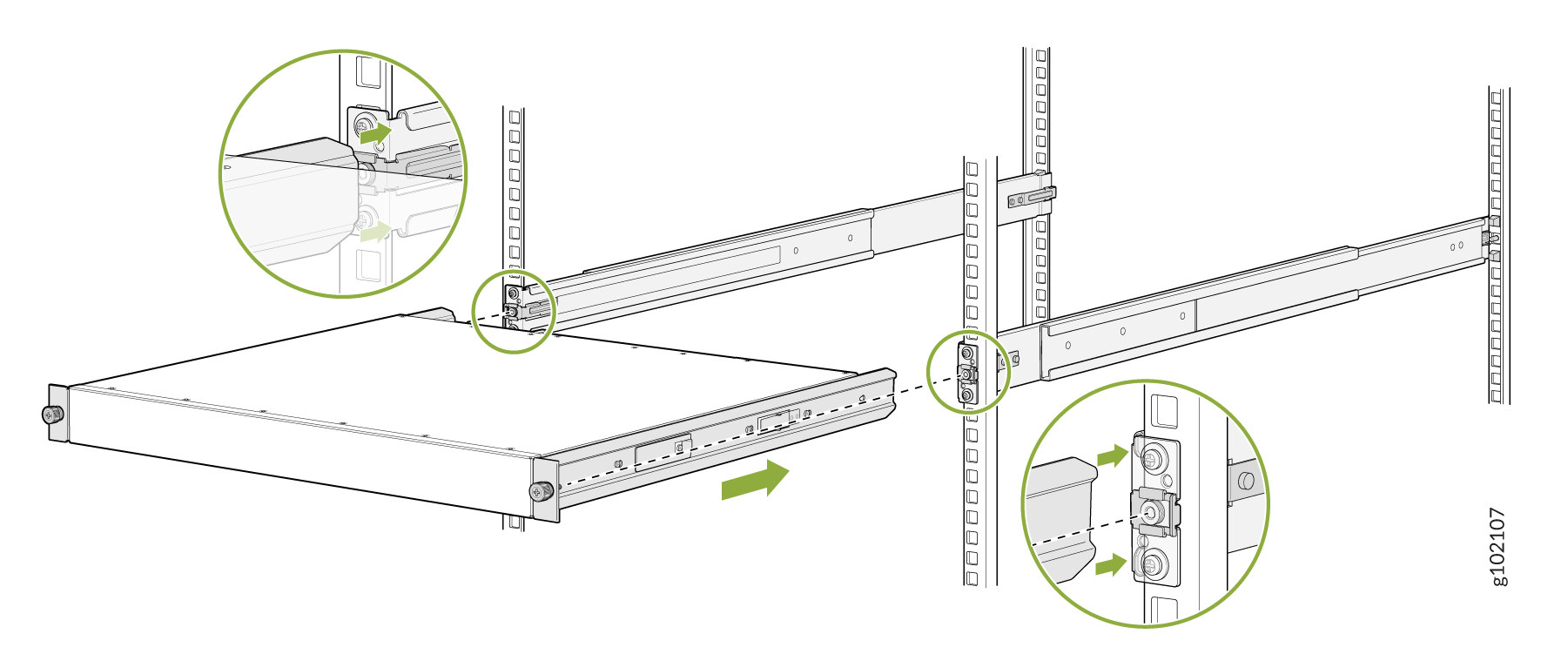
- Tighten the two thumbscrews to secure the device.
Connect to Power
To connect the QFX5130-48C/ QFX5130-48CM switch to AC power, you must perform the following tasks:
- Ground the QFX5130-48C/ QFX5130-48CM Switch
- Connect the Power Cord and Power On the QFX5130-48C/ QFX5130-48CM Switch
Ground the QFX5130-48C/ QFX5130-48CM Switch
To ground the QFX5130-48C/QFX5130-48CM switch:
Wrap and fasten one end of the ESD cable grounding strap around your bare wrist, and connect the other end to a site ESD point.
Connect the grounding cable to a proper earth ground, such as the rack in which you mount the device.
Secure the grounding cable terminal to the grounding bracket using the 10-32 screws.
Loosen the two screws that are attached to the chassis.
Place the bracket attached to the grounding cable over the grounding point.
Tighten the two screws.
- Figure 12: Ground the QFX5130-48C/ QFX5130-48CM Switch
Dress the grounding cable. Ensure that the cable doesn’t block access to or come in contact with other device components, and that it doesn’t drape where people could trip on it.
Connect the Power Cord and Power On the QFX5130-48C/ QFX5130-48CM Switch
For information about the supported AC power cord specifications, see AC Power Cord with Type C15 Coupler Specifications.
To connect the power cord:
Ensure that the power supply is fully inserted in the rear panel of the switch.
Insert the coupler end of the power cord into the AC power cord socket on the rear panel.
Push the power cord retainer on to the power cord.
Figure 13: Connect the Power Cord to a QFX5130-48C Switch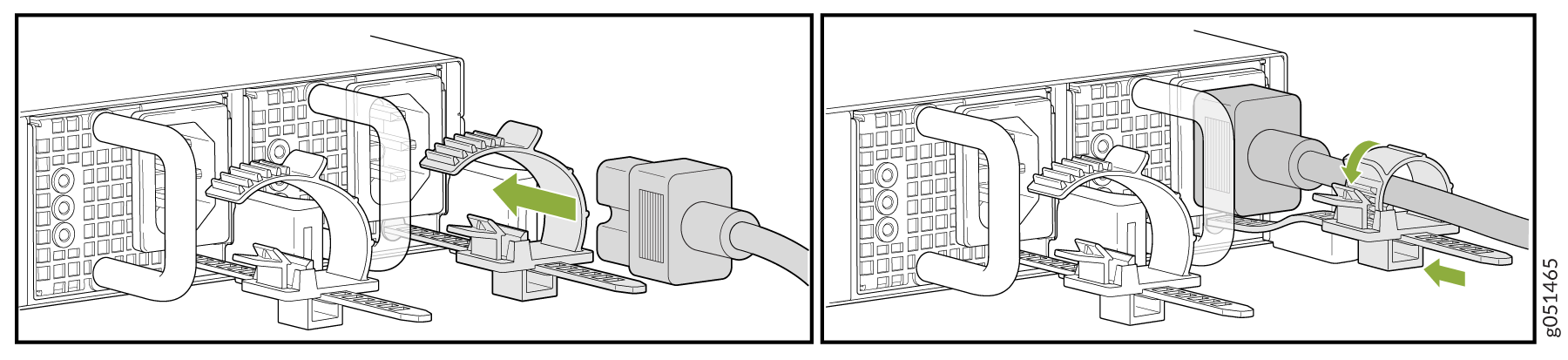
If the AC power source outlet has a power switch, turn it off.
Plug the power cord into an AC power source outlet.
If the AC power source outlet has a power switch, turn it on. The switch doesn't have a power switch and powers on as soon as you plug it in.