How to Install a ORv3-Compliant Switch with Tray Assembly (2OU) in Your ORv3 Rack
Use the information in this topic to install the Open Rack V3-compliant switch with tray assembly in an ORv3 rack.
The Open Rack V3 (ORv3)-compliant switch with tray assembly (henceforth written as switch-tray assembly in this topic) features a switch that comes pre-assembled in the tray, making the installation process quick and straightforward.
Use this ORv3-compliant tray only with the listed or certified Juniper product. Failure to comply might result in damage.
Unpack the Switch-Tray Assembly
We ship the switch-tray assembly in a cardboard carton, secured with foam packing material.
The switch-tray assembly has maximum protection inside the shipping carton. Do not unpack the switch until you are ready to begin installation.
To unpack the switch-tray assembly:
- Move the shipping carton to a staging area as close to the installation site as possible. Make sure that you have enough room to remove the system components.
- Position the carton so that the arrows are pointing up.
- Open the top flaps on the shipping carton.
- Remove the accessory box and verify the contents in it against the parts inventory on the label attached to the carton.
- Pull out the packing material holding the assembly in place.
- Verify the chassis components received against the packing list included with the switch-tray assembly.
- Save the shipping carton and packing materials in case you need to move or ship the switch-tray assembly later.
Parts Inventory (Packing List)
The shipment includes a packing list. Check the parts you receive in the shipping carton against the items on the packing list. We ship the parts as per the configuration that you order.
If any part on the packing list is missing, contact your customer service representative or contact Juniper customer care from within the U.S. or Canada by telephone at 1-888-314-5822. For international-dial or direct-dial options in countries without toll-free numbers, see https://www.juniper.net/support/requesting-support.html.
- Parts List for QFX5130 Switch-Tray Assembly
- QFX5130 Switch-Tray Assembly: Components and Model Numbers
- Parts List for the Accessory Kit
|
Component |
Quantity |
Open Unit (OU) |
|---|---|---|
|
Preassembled tray with switch (DC switch model) |
1 |
2OU |
|
Component Type |
Model Number |
|---|---|
|
Preassembled tray with switch (DC switch model) |
QFX513032CDDAFO-T2 |
|
DC PSU |
JPSU-1600W1UDCAFO2 |
|
Fan |
QFX5220-32CDFANAO2 |
| Component | Quantity |
|---|---|
|
Warranty card |
1 |
|
End User License Agreement (EULA) |
1 |
|
Documentation roadmap card |
1 |
Install Switch-Tray Assembly in an ORv3 Rack
Before installing the switch-tray assembly in an ORv3 rack:
-
Verify that the site meets the requirements described in the Site Preparation Checklist of the switch.
-
Place the rack in its permanent location, allowing adequate clearance for airflow and maintenance, and secure it to the building structure.
-
Read General Safety Guidelines and Warnings, with particular attention to Chassis and Component Lifting Guidelines.
To install the switch-tray assembly in an ORv3 rack:
-
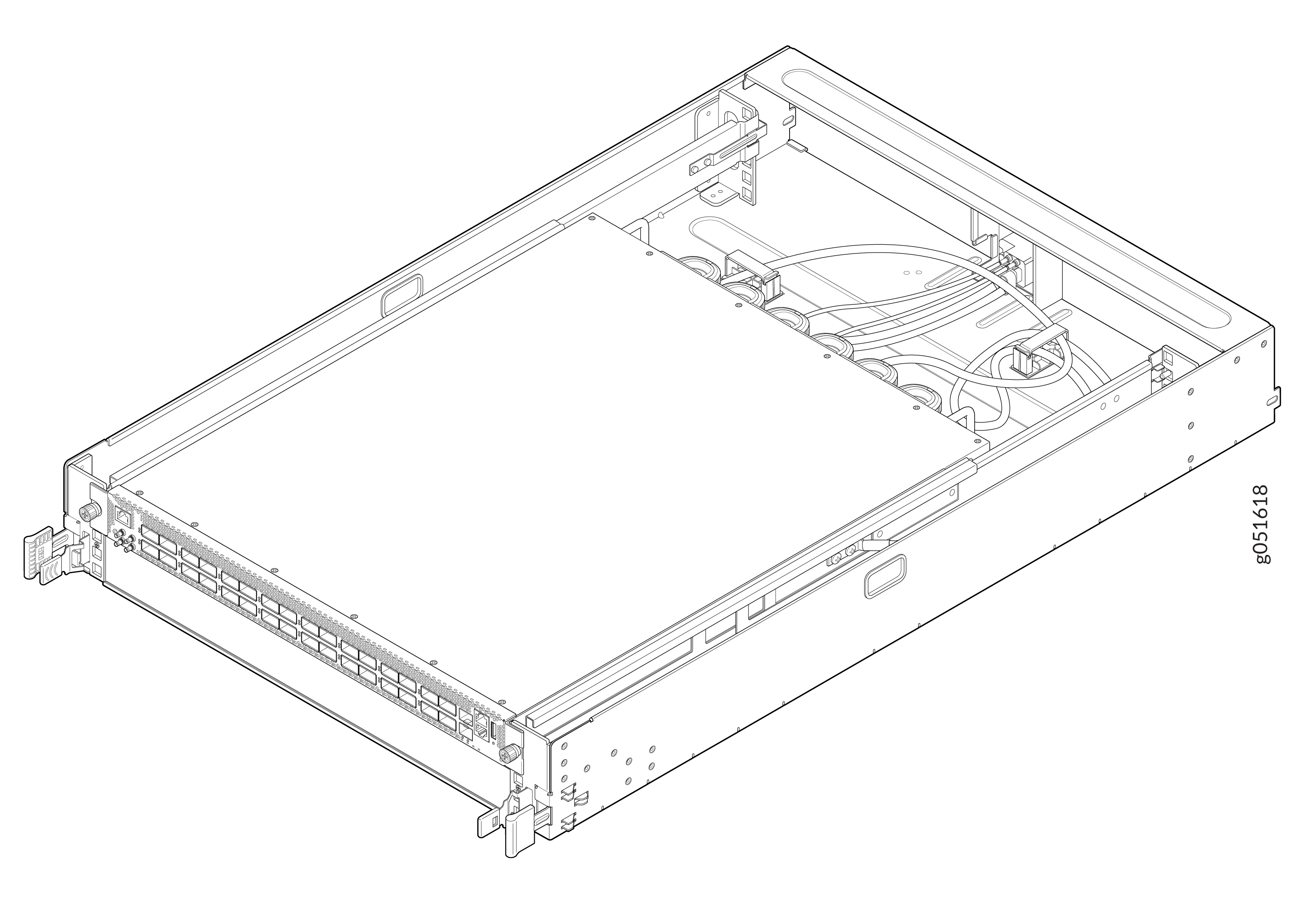
Remove the tray assembly from shipping carton.
Figure 1: Switch-Tray Assembly
-
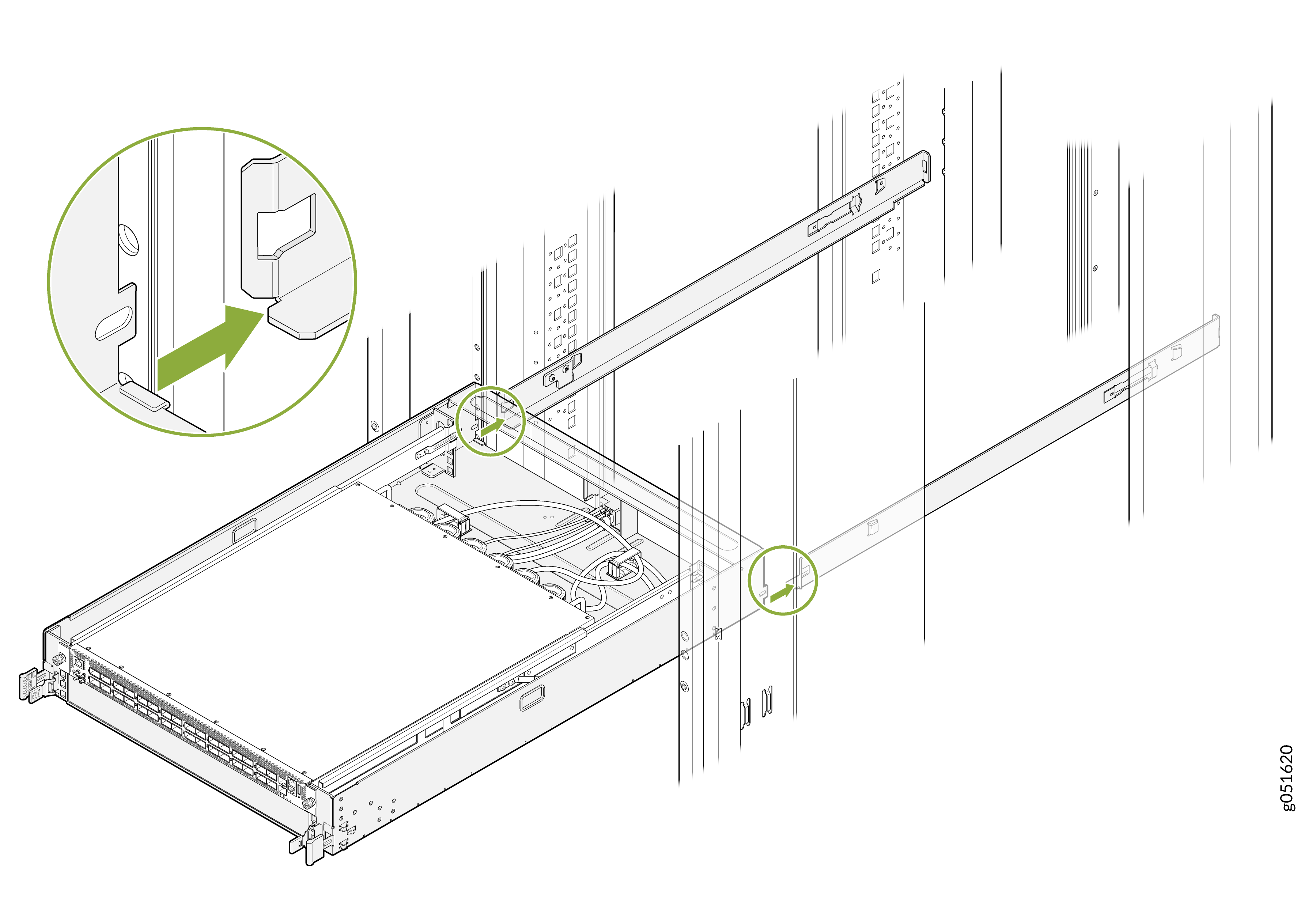
Carefully align the switch-tray assembly with the rails in the rack.
Figure 2: Align the Switch-Tray Assembly with the rails
-
Slide the switch-tray assembly into the rack until the IT Gear Input Connector at the
rear of the switch-tray assembly fully engages with the bus bar.
Figure 3: Slide the Switch-Tray Assembly into the Rack
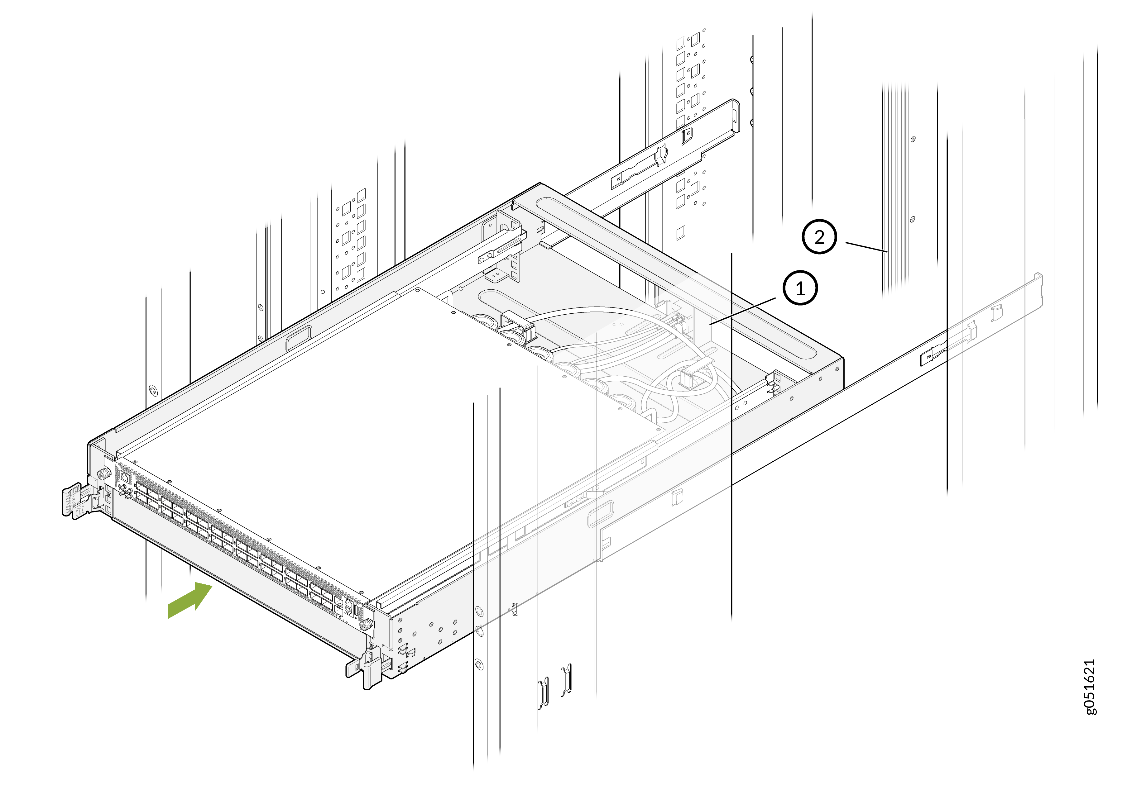
Table 4: Component Callouts Callout Description 1
IT Gear Input Connector
2
Bus bar
Note:The bus bar delivers power to the switch.
When the switch‑tray assembly is fully inserted into the rack, the latch locking tabs engage with the rack’s rail to secure the tray in place.
Figure 4: Fully Inserted Switch-Tray Assembly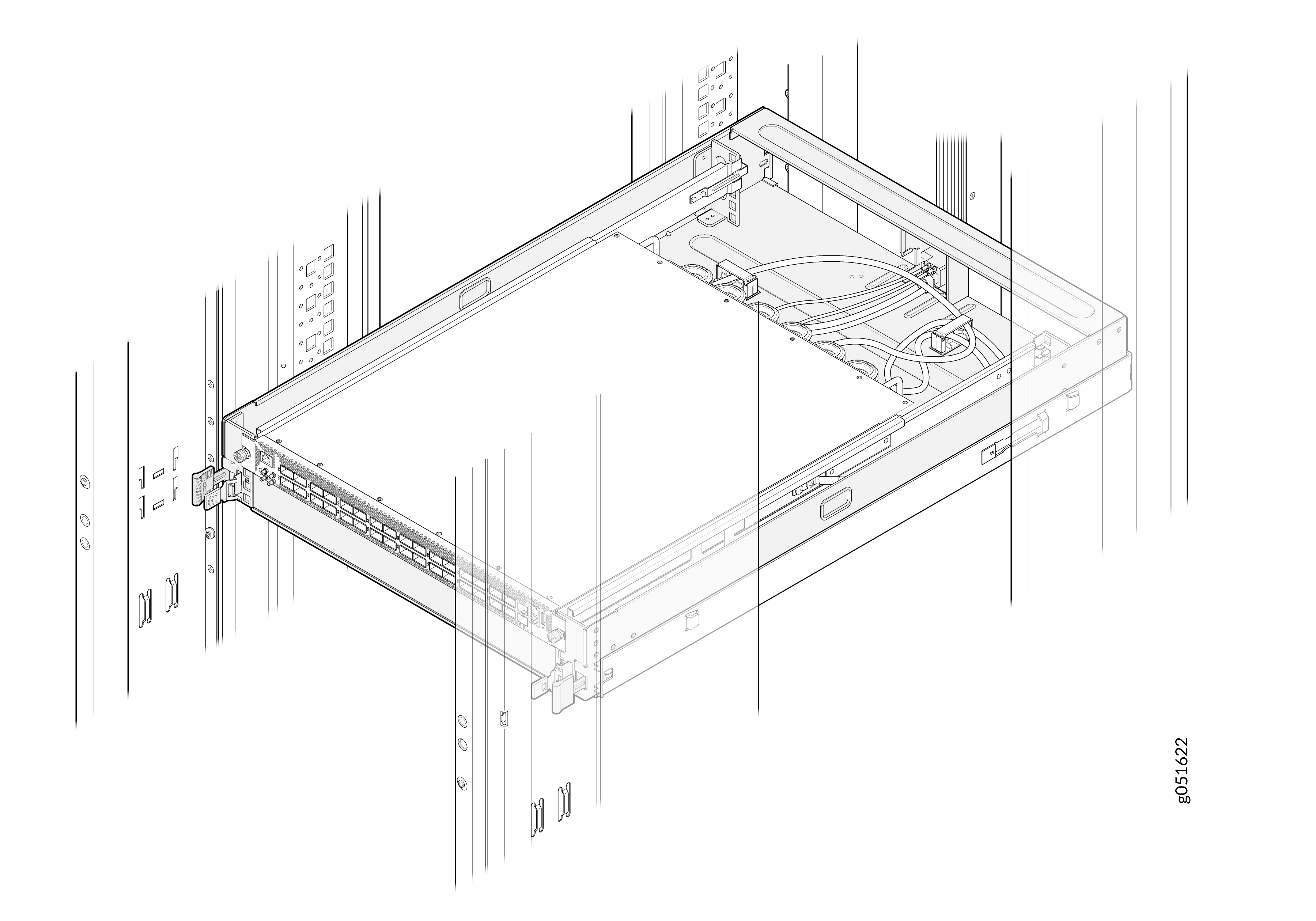 Note: For the switch-tray assembly installed in an ORv3 rack, you do not require an additional grounding or power configuration. The ORv3 rack infrastructure provides integrated power delivery and grounding. Ensure you install and ground the rack properly according to site standards.
Uninstall the Switch-Tray Assembly from the ORv3 rack
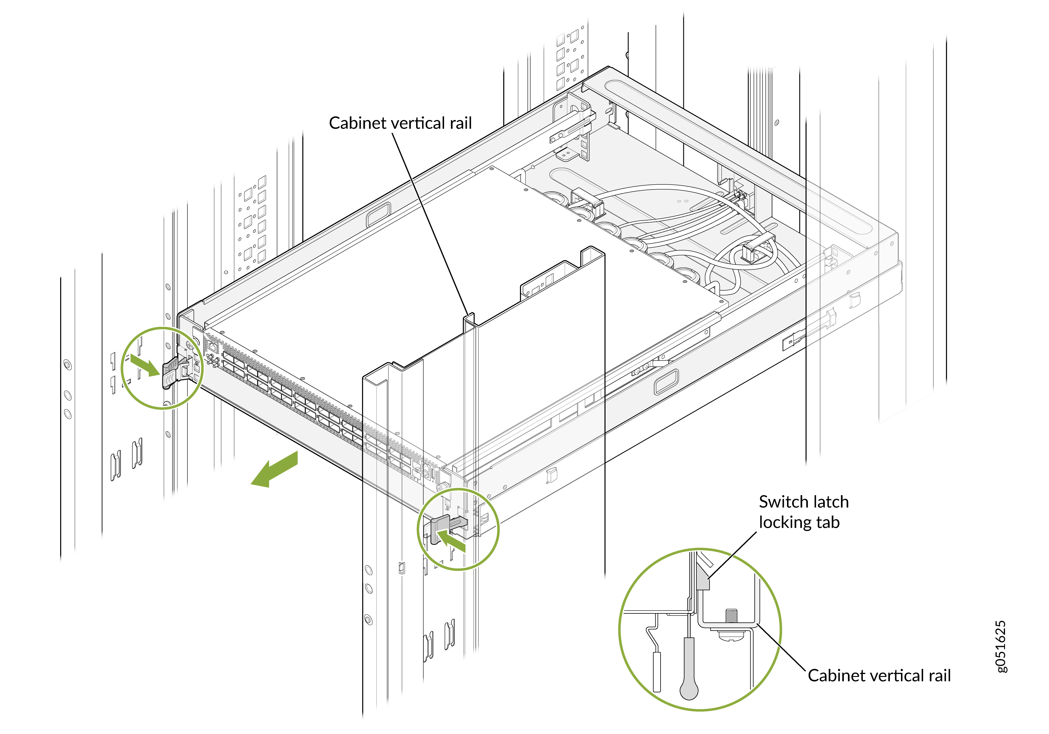
-
Locate the latch locking tabs on both sides of the switch-tray assembly.
Figure 5: Locate the Latch Locking Tabs
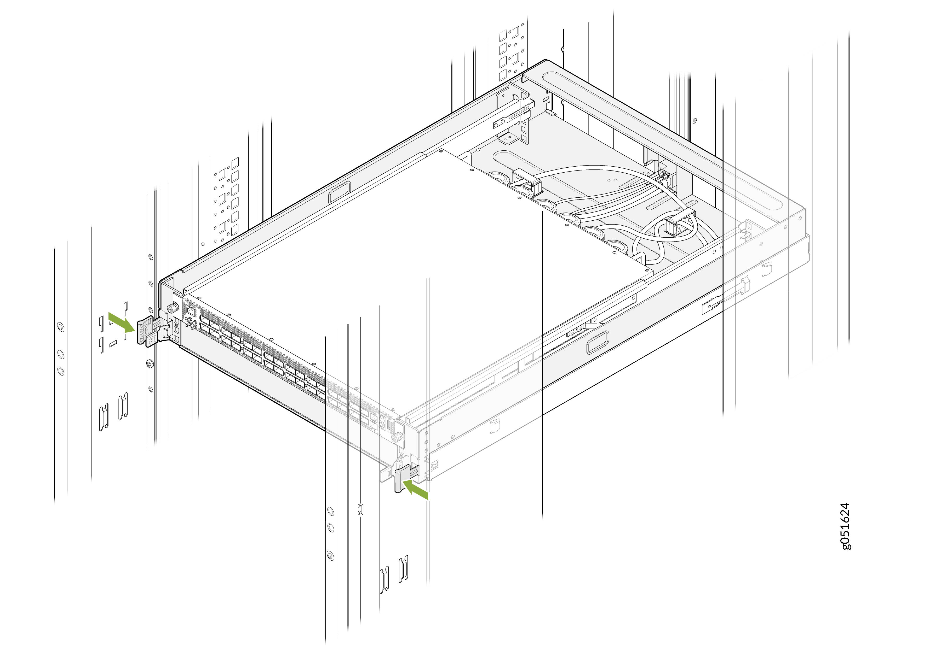
-
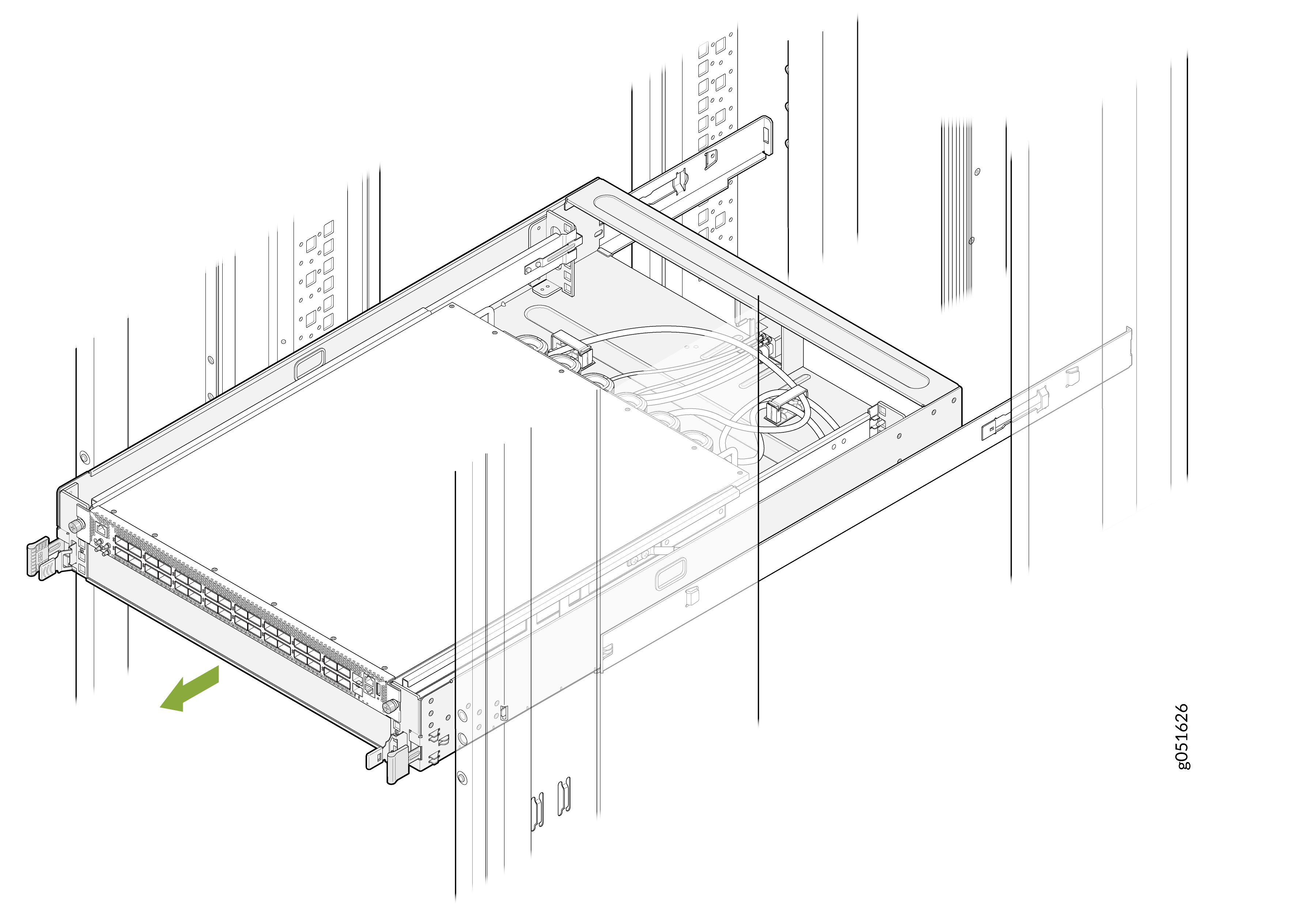
Push the latch locking tabs inward on both sides to release the switch-tray assembly
from the rack post and gently slide the switch-tray assembly out of the ORv3 rack at same
time.
Note: Do not release the latch locking tabs before pulling the switch-tray assembly out. Both actions must be done simultaneously.Figure 6: Slide the Switch-Tray Assembly Out
Ground the Switch-Tray Assembly
To meet safety and electromagnetic interference (EMI) requirements and to ensure proper operation, you must connect the ORv3 rack to the earth ground.
You don't need to make any external connections to ground the switch-tray assembly. The switch-tray assembly is connected to earth ground when you slide in the tray.
The switch-tray assembly gets earth ground protection by virtue of these features: