QFX5130 Port Panel
The port panel of the QFX5130-32CD/QFX5130E-32CD has 32 high-speed ports that support transmission at 400-gigabit per second (Gbps), 100-Gbps, or 25-Gbps speeds. It also has two dedicated ports for 10 Gbps.
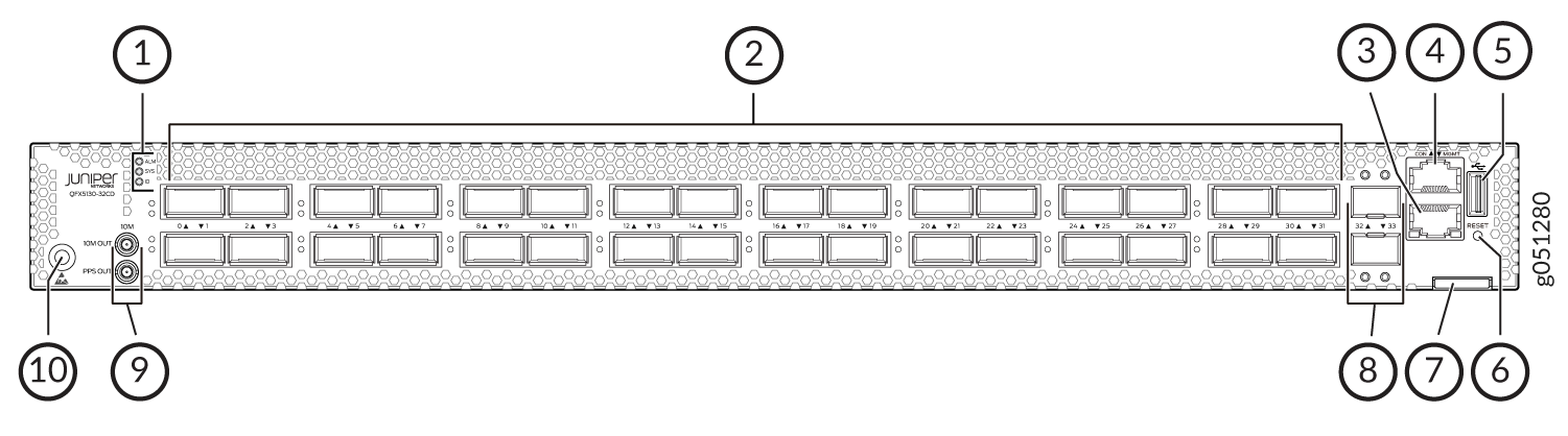
1 — Chassis status LEDs | 6 — Reset button (do not use unless directed by JTAC) |
2 — 2 400-Gbps QSFP-DD network ports. | 7 — Chassis serial number pull-out |
3 — RJ-45 management port (100 Mbps/1000 Mbps/10000 Mbps) | 8 — 2 ports dedicated to 10-Gigabit Ethernet (GbE). |
4 — RJ-45 console port | 9 — Output connectors [10 megahertz (MHz) and 1 pulses per second (PPS)] |
5 — USB port (USB 2.0/3.0 standard) | 10 — Electrostatic discharge (ESD) grounding point |
Network Ports for QFX5130-32CD
The QFX5130-32CD/QFX5130E-32CD network ports (0 through 31) support:
400-Gbps QSFP-DD direct attach copper (DAC) cables.
400-Gbps active optic cable (AOC) (starting in Junos OS Evolved Release 20.4R1).
100-Gbps QSFP28 transceivers.
Channelizing a 100-Gbps QSFP28 port into four 25-Gbps SFP interfaces with active optical breakout (AOCBO) cables.
Channelizing each 40-Gbps QSFP+ port into four 10-Gbps SFP+ ports with direct attach copper breakout (DACBO) cables. This support is available starting from Junos OS Evolved Release 20.4R1. OR This support is available in Junos OS Evolved Release 20.4R1 and later
The port panel of the QFX5130-48C and QFX5130-48CM switch has 48 100GbE ports that support SFP56-DD transceivers for server connectivity. The port panel also has 8 400GbE uplink ports that support QSFP-DD transceivers.
Network Ports for QFX5130-48C
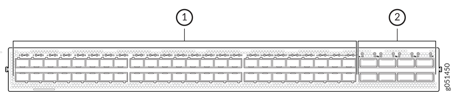
1 — 48 high-speed 100GbE network ports | 2 — 8 high-speed 400GbE uplink ports |
The QFX5130-48C network ports (0 through 47) support:
100-Gbps SFP56-DD cables.
400-Gbps active optic cables (AOCs).
Channelization of each 40 Gbps QSFP+ port to four 10-Gbps SFP+ ports with DACBO cables. This support is available in Junos OS Evolved Release 20.4R1 and later.
Network ports are 0-47; uplink ports are ports 48-55. We don't see 56 and 57 in the ports panel.
When you use the Reset button, only the device gets rebooted and there is no change to the existing configuration of the switch. The device does not return to the factory-default configuration.
When you use Finisar AOC SFP+ optical cables along with the QFX5130-48C switch, you need to pull upwards to pull out the module easily from the cage.
Setting Port Speed and Channelization
For QFX5130-32CD/QFX5130E-32CD, the default speed for ports 0 through 31 is 400 Gbps. Only QSFP-DD optics inserted in these ports will link without configuration. See Table 1 .
The last two SFP+ ports cannot support 1-GbE modules. These two ports support only 10-GbE modules.
Transceiver |
Sets Default Speed to |
|---|---|
QSFP-DD |
400 Gbps, link up |
QSFP28 |
400 Gbps, link down |
QSFP |
400 Gbps, link down |
SFP+ (ports 32 and 33 only) and management port |
10 Gbps, link up |
The QFX5130-32CD/QFX5130E-32CD does not support autonegotiation between devices.
For QFX5130-48C, the default speed for ports 0through 47 is 100 Gbps. Only SFP56-DD optics inserted in these ports will link without configuration. The default speed for ports 48 to 55 is 400 Gbps. Only QSFP-DD optics inserted in these ports will link without configuration. See Table 2.
Transceiver |
Sets Default Speed to |
|---|---|
QSFP-DD |
400 Gbps, link up |
QSFP28 |
400 Gbps, link down |
QSFP |
400 Gbps, link down |
SFP+ (ports 56 and 57 only) |
10 Gbps, link up |
SFP56-DD |
100 Gbps, link up |
If a port already has a speed configured, you can manually configure the ports.To set the speed, use the set interfaces et-0/0/0 speed speed CLI command in configuration mode. For example, to set port 2 to 100 Gbps, use the following command:
            user@host> configure
user@host#set interfaces et-0/0/2 speed 100g
On QFX5130 devices, there is a single FPC and PIC, which is always 0.
You can channelize the port into four independent 25-Gigabit or 10-Gigabit Ethernet interfaces by configuring the number of subports and the speed. For more information, see https://apps.juniper.net/hct/ and https://www.juniper.net/documentation/us/en/software/junos/interfaces-ethernet-switches/index.html. You can use the set interfaces et-0/0/x speed (25g | 10g) number-of-sub-ports number-of-sub-ports command. For example, to configure a 40-Gbps port into four independent 10-Gbps interfaces, use the following command:
[edit interfaces]
user@host# set et-0/0/x speed 10g number-of-sub-ports 4
Be sure to save and commit your changes.
QFX5130-32CD/QFX5130E-32CD Network LEDs
The high-speed QSFP-DD network ports use a single bicolored LED to indicate link status, activity on the link, or a fault condition. The 10-Gbps SFP+ ports have separate bicolored LEDs; the left LED indicates link and activity and the right LED indicates fault conditions. See Figure 3.
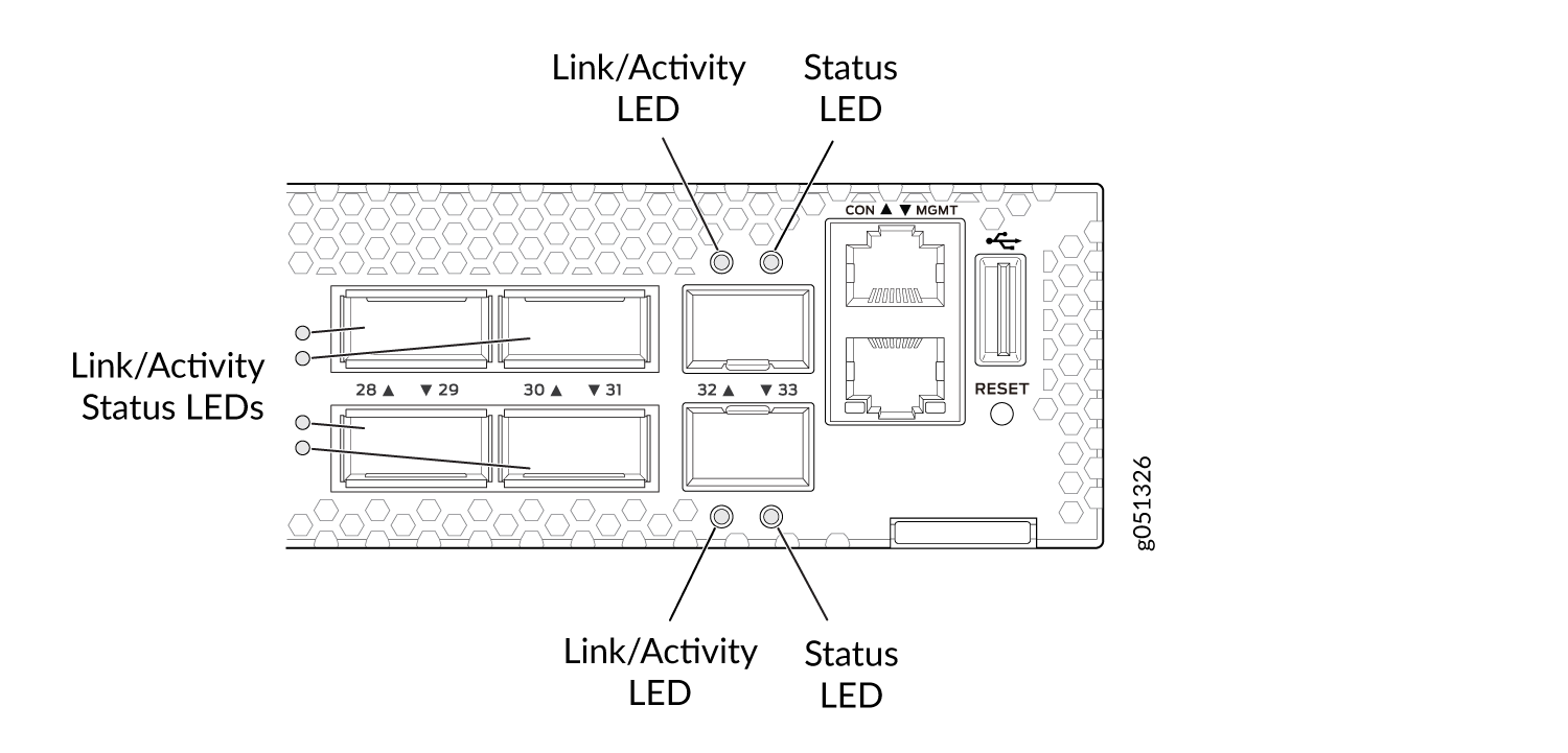
Table 3 describes the various states of the network port LEDs for the QSFP-DD high-speed ports. Table 4 describes how to interpret the link and activity LEDs and the status LEDs for the SFP+ ports.
Color |
State |
Channelized |
Description |
|---|---|---|---|
Unlit |
Off |
No |
Off is the default mode. The LED can be unlit even when power is present and a transceiver is present in the port.
|
Yes |
The port is administratively disabled. |
||
Green |
On steadily |
No |
A 400-Gbps or 100-Gbps link is established, but there is no activity. |
Yes |
All channels or subports have links established, but there is no activity. |
||
Flashing |
No |
A 400-Gbps or 100-Gbps link is established, and there is link activity. |
|
Yes |
All the channels or subports have links established, and there is link activity. |
||
All LEDs blipping (slow flashing) |
Either |
The beacon feature is activated (service request). |
|
Amber |
Blinking |
Either |
One or more interface or connection errors have occurred. |
Flashing |
Yes |
At least one channel or subport has a link established, but not all channels or subports have links established. |
LED |
Color |
State |
Description |
|---|---|---|---|
Link/Activity |
Off |
Link down |
Link down—The port does not have a connection. |
Green |
On steadily |
Link up—The port has a connection, but there is no activity. |
|
Flashing |
Active link—The port has a connection, and there is activity. |
||
Blipping (slow flashing) |
Beacon–The port has a service request. |
||
Status |
Green |
On steadily |
The port is configured for 10 Gbps. |
Amber |
Blinking |
Fault–The port has an interface error. |
QFX5130-48C Network LEDs
The high-speed QSFP-DD and SFP-DD network ports use a single bi-colored LED to indicate link status, activity on the link, or a fault condition. The 10-Gbps SFP+ ports have single bi-colored LEDs that indicate link, activity, and fault conditions. See Figure 4.
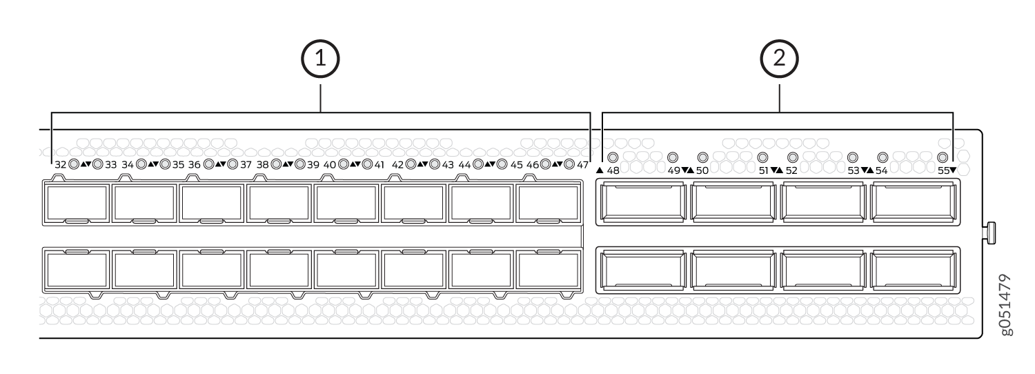
Table 5 describe the various states of the network port LEDs for the QSFP-DD/SFP-DD high-speed ports. Table 6describe how to interpret the link and activity LEDs and the status LEDs for SFP+ ports.
Color |
State |
Channelized |
Description |
|---|---|---|---|
Unlit |
Off |
No |
Off is the default mode. The LED can be unlit even when power is present and a transceiver is present in the port.
|
Yes |
The port is administratively disabled. |
||
Green |
On steadily |
No |
A 400-Gbps or 100-Gbps link is established, but there is no activity. |
Yes |
All the channels or the subports have links established, but there is no activity. |
||
Flashing |
No |
A 400-Gbps or 100-Gbps link is established, and there is link activity. |
|
Yes |
All the channels or the subports have links established, and there is link activity. |
||
All LEDs blipping (slow flashing) |
Either |
Indicates that the beacon feature is activated (service request). |
|
Amber |
Blinking |
Either |
One or more interface or connection errors have occurred. |
Flashing |
Yes |
At least one channel or subport has a link established, but not all channels or subports have links established. |
Normal Mode |
Beacon On (Port Location) |
Description |
|---|---|---|
Unlit |
Off |
The port is administratively disabled, there is no power, the link is down, or there is a fault. |
Green |
Green, blinking |
Link is established, but there is no activity. |
Green |
Green, blinking |
Link is established, and there is activity. |
Red |
Red, blinking |
Link is not established, and there is a hardware transceiver failure. |
Green |
Green, blinking |
Link is not established, and there is a loss of signal (LOS) detected. |
Amber |
Amber, blinking |
Link is not established, and there is some other fault apart from the LOS and hardware transceiver failure. |
Amber |
Amber, blinking |
The port has been explicitly disabled in the CLI. |
Green |
Green, blinking |
Anything except disabled port but no transceiver is present. |