Fast Track to Rack Installation and Power
This procedure walks you through the most basic steps for installing your QFX5120 switch in a rack and connecting it to power.
You can mount the QFX5120-48T, QFX5120-48Y, and QFX5120-48YM switches in a four-post rack or cabinet using the JNP-4PST-RMK-1U-E rack mount kit. We’ll walk you through the steps to install an AC-powered switch in a square hole four-post rack.
You can mount a QFX5120-32C switch on four posts of a 19-in. rack or cabinet by using a rack mount kit. See Mount a QFX5120-32C Switch on a Four-Post Rack.
Before you install the switch, review:
Install the QFX5120-48T/QFX5120-48Y/QFX5120-48YM Switch in a Rack
To mount the device by using the partial tool less JNP-4PST-RMK-1U-E rack mount kit on a square hole rack:
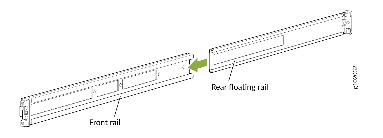
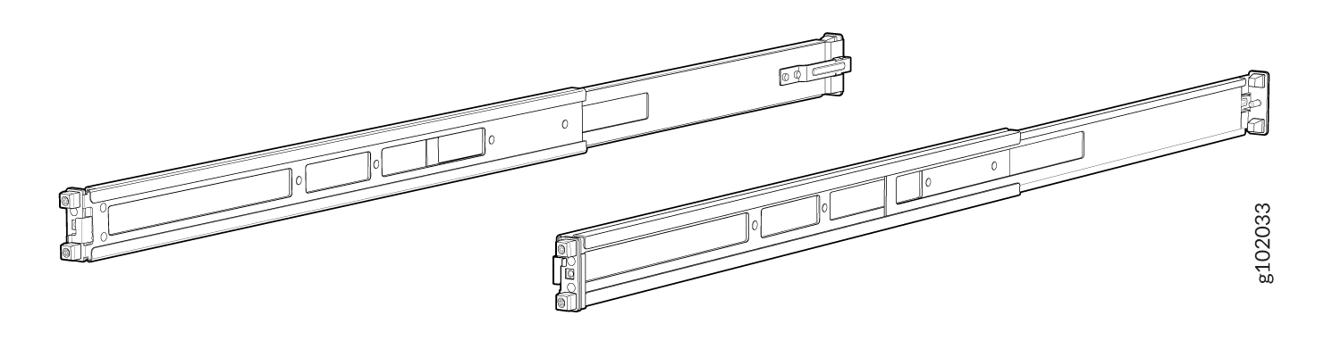
- Assemble the mounting rails.
-
Attach the mounting rails to the rack.
-
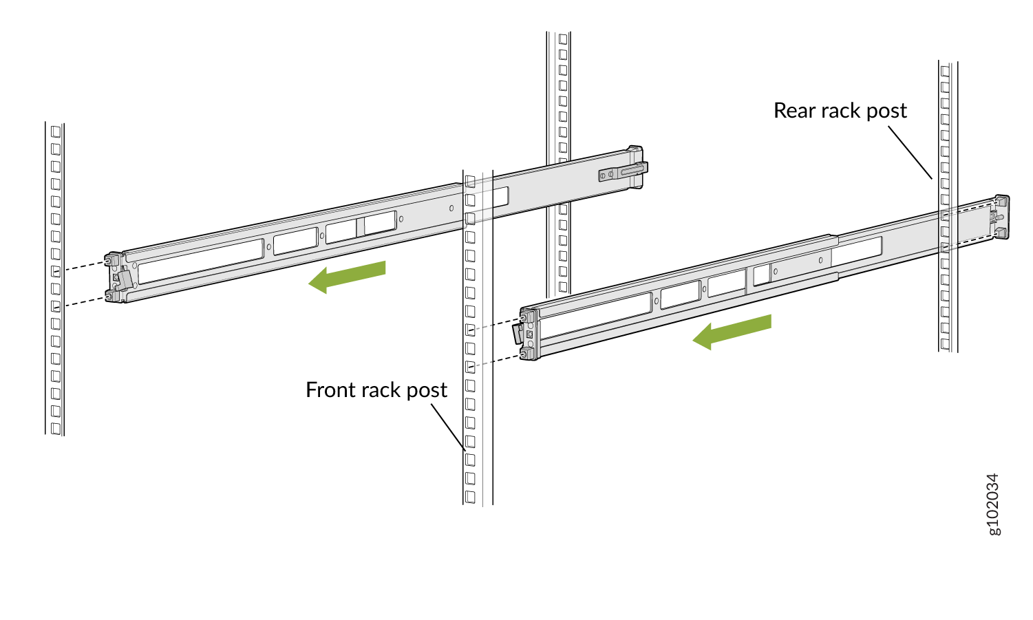
Align the guide blocks of the rear mounting rails with the
rear-post holes. Pull the rear mounting rails toward the front of
the rack to lock the rails in place. You will hear a click sound
when the latch locks into the corresponding rack holes. See Figure 3.
Figure 3: Install the Rear Floating Rails
-
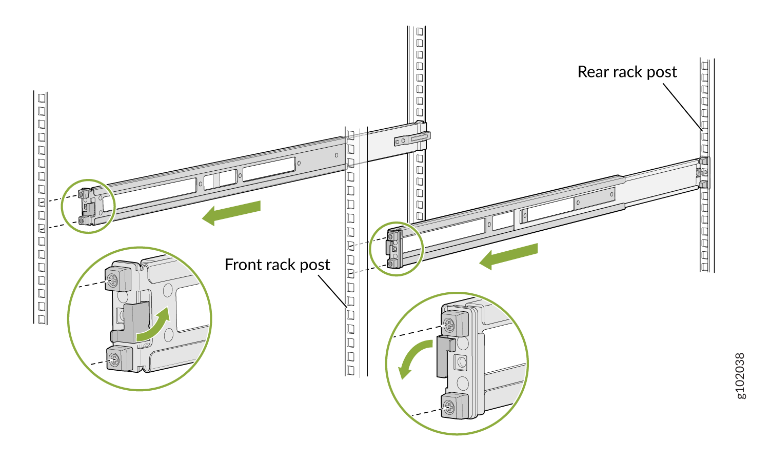
Move the latch lock on the front mounting rails to open position,
slide the front mounting rails, and insert the guide blocks into the
front rack posts. See Figure 4.
Figure 4: Install the Front Mounting Rails
-
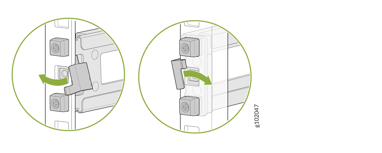
Push the lock latch to the locked position. See Figure 5.
Figure 5: Front Mounting Rails Lock Latch
-
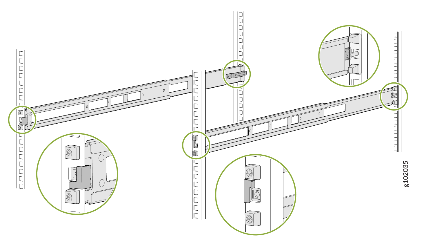
Visually ensure that the front and rear latches are locked into
place on the mounting rails. See Figure 6.
Figure 6: Mounting Rails Installed and Locked
-
Align the guide blocks of the rear mounting rails with the
rear-post holes. Pull the rear mounting rails toward the front of
the rack to lock the rails in place. You will hear a click sound
when the latch locks into the corresponding rack holes. See Figure 3.
-
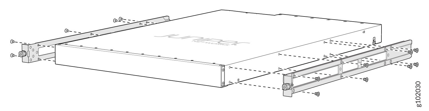
Attach mounting brackets to the device if not pre-installed. If your device
already has the mounting brackets pre-installed than skip this step and move
to the next step.
-
Insert the flat head M4 x 6mm Phillips screws to attach the
mounting bracket into the aligned holes on the chassis (see Figure 7).
Tighten the screws.
Figure 7: Attach the Mounting Brackets to the Device
-
Insert the flat head M4 x 6mm Phillips screws to attach the
mounting bracket into the aligned holes on the chassis (see Figure 7).
Tighten the screws.
-
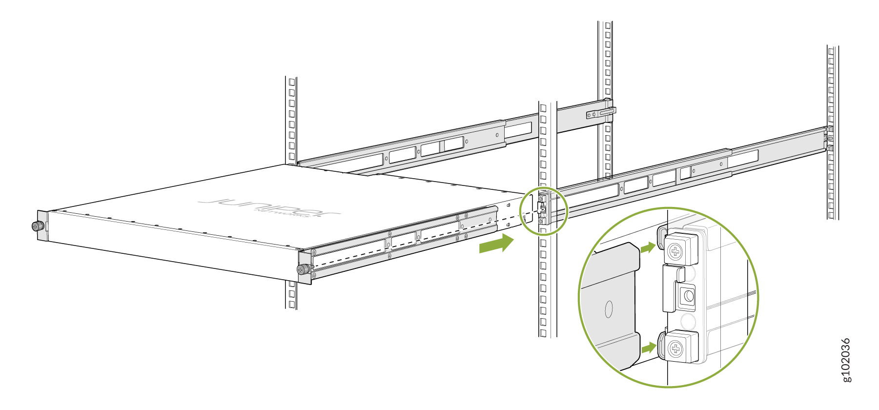
Grasp both sides of the device, lift it, and position the device such that
the mounting rails slide into the channels of the mounting brackets. See
Figure 8.
Figure 8: Slide the Device into the Rack
-
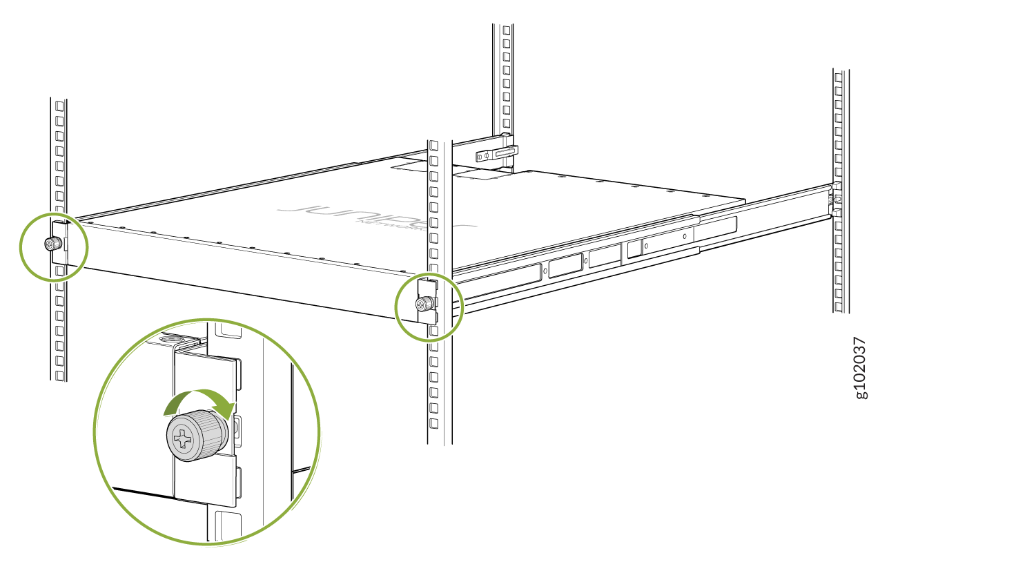
Tighten the two thumbscrews to secure the device. See Figure 9.
Figure 9: Tighten the Thumb Screws
Connect to Power
Ground the QFX5120 Switch
To ground the QFX5120 switch:
Wrap and fasten one end of the electrostatic discharge (ESD) cable grounding strap around your bare wrist, and connect the other end to a site ESD point.
- Connect one end of the grounding cable to a proper earth ground, such as the rack in which the switch is mounted.
- Place the grounding lug attached to the grounding cable over the protective
earthing terminal:
On the rear panel of a QFX5120-32C switch (see Figure 10).
On the left panel on QFX5120-48T and QFX5120-48Y switches (see Figure 11).
On the left panel on a QFX5120-48YM switch (see Figure 12, Figure 13, Figure 14, or Figure 15).
Figure 10: Connect a Grounding Cable to the QFX5120-32C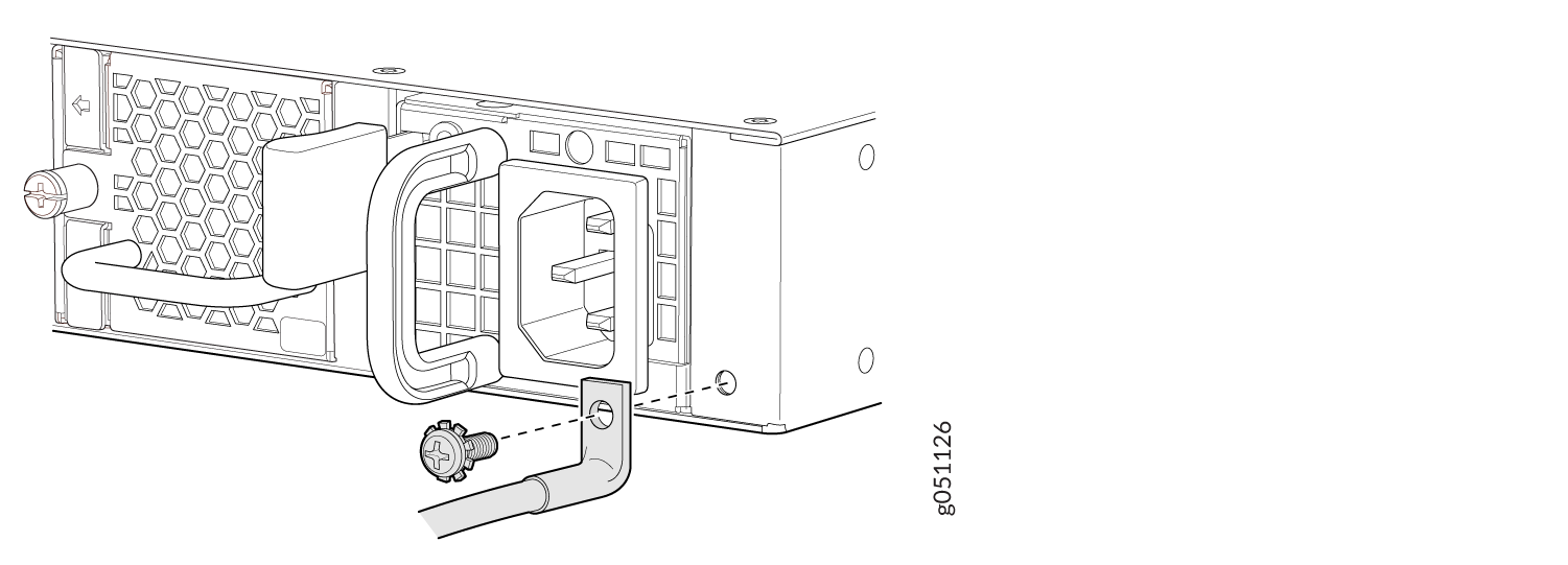 Figure 11: Connect a Grounding Cable to the QFX5120-48T or QFX5120-48Y
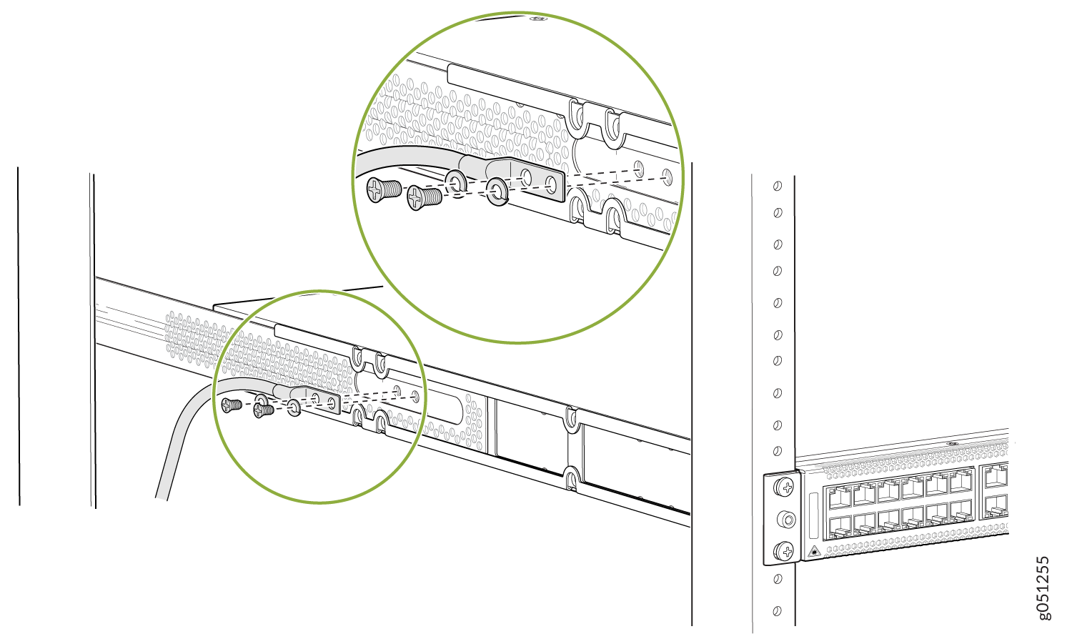 Figure 12: Connect a Grounding Cable to the Protective Earthing Terminal in the Rear of the Left Panel on the QFX5120-48YM Mounted on Four Posts
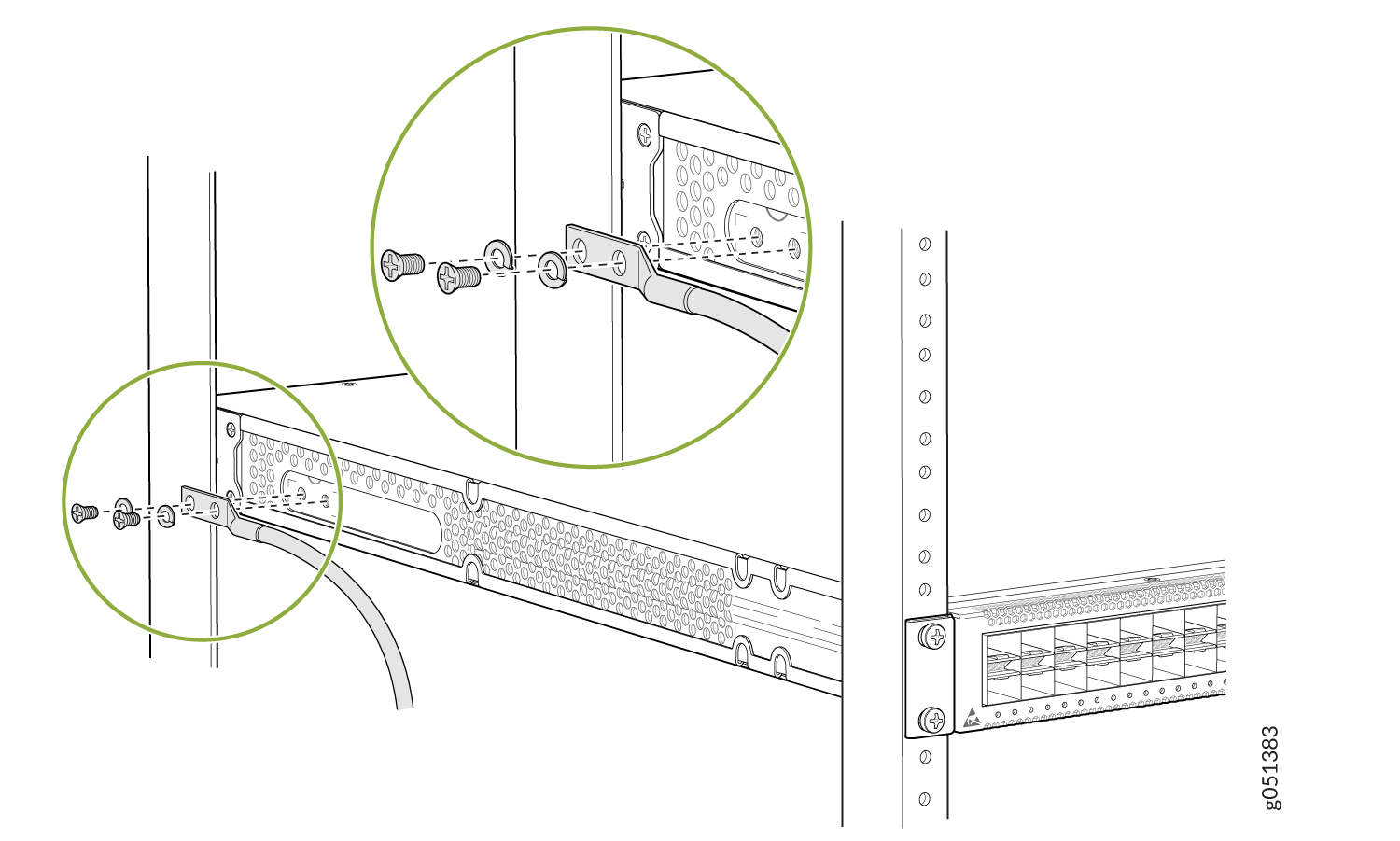 Figure 13: Connect a Grounding Cable to the Protective Earthing Terminal in the Front of the Left Panel on the QFX5120-48YM Mounted on Four Posts
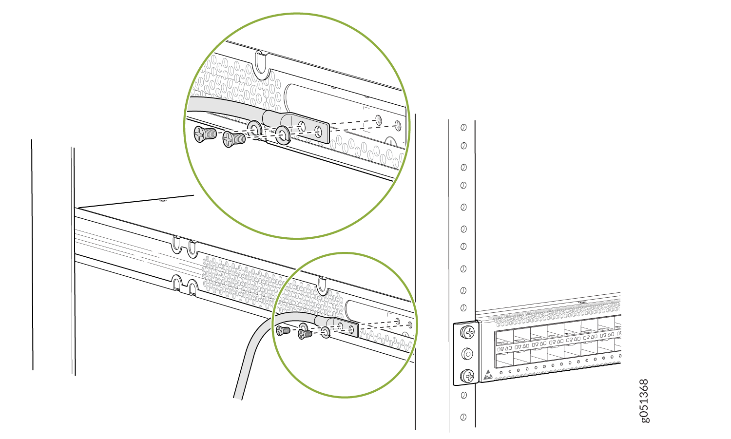 Figure 14: Connect a Grounding Cable to the Protective Earthing Terminal in the Rear of the Left Panel on the QFX5120-48YM Mounted on Two Posts
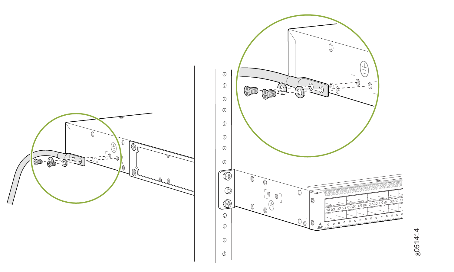 Figure 15: Connect a Grounding Cable to the Protective Earthing Terminal in the Front of the Left Panel on the QFX5120-48YM Mounted on Two Posts
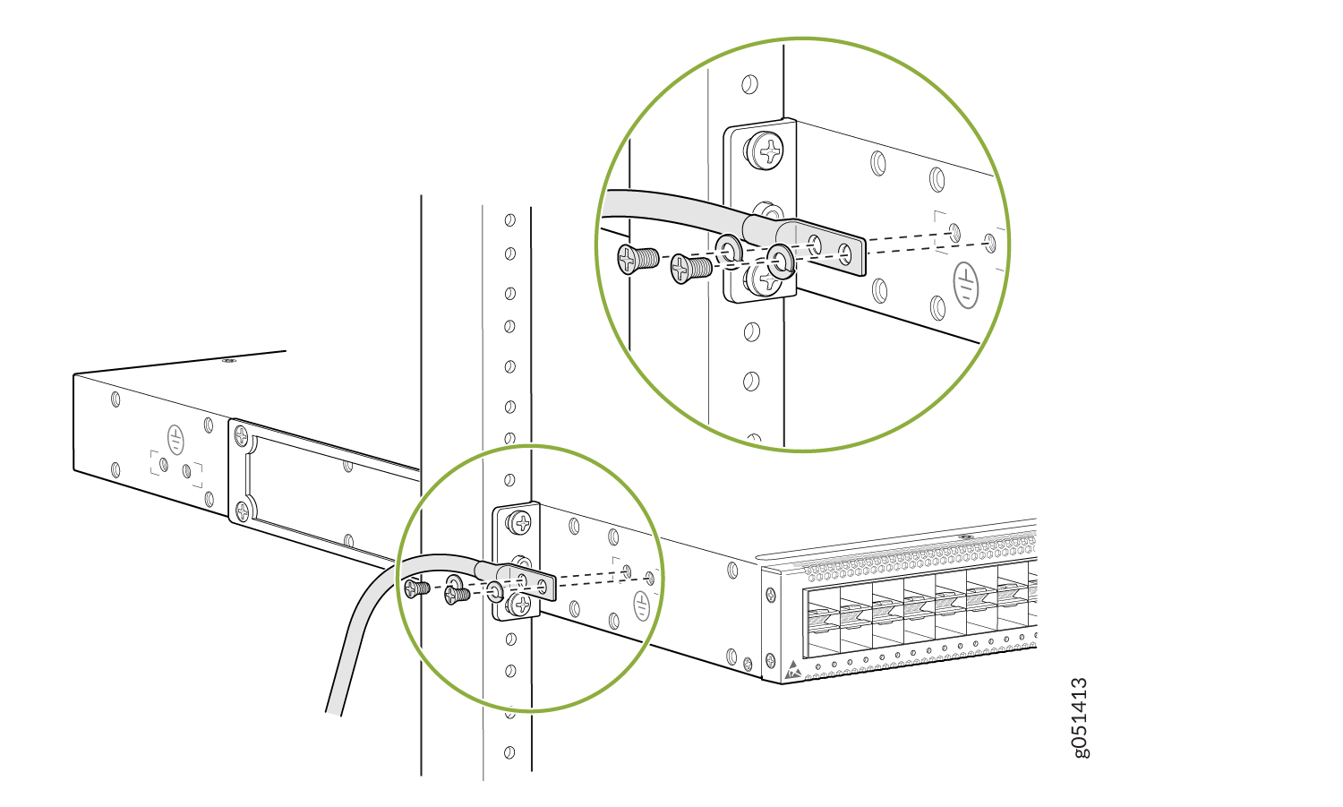
- Secure the grounding lug to the protective earthing terminal with the screws.
- Dress the grounding cable and ensure that it does not touch or block access to other switch components.
Ensure that the cable does not drape where people could trip over it.
Connect Power to an AC-Powered QFX5120 Switch
To connect power to an AC-powered QFX5120 switch:
Wrap and fasten one end of the ESD wrist strap around your bare wrist, and connect the other end of the strap to a site ESD point.
Ensure that the power supplies are fully inserted in the chassis.
Locate the power cord or cords shipped with the switch; the cords have plugs appropriate for your geographical location.
Warning:Ensure that the power cord does not block access to device components or drape where people can trip on it.
Connect the power cord.
For QFX5120-32C, QFX5120-48T, and QFX5120-48Y switches:
Push the end of the retainer strip into the hole next to the inlet on the power supply faceplate until it snaps into place. Ensure that the loop in the retainer strip faces the power cord.
Press the small tab on the retainer strip to loosen the loop. Slide the loop until you have enough space to insert the power cord coupler into the inlet.
Insert the power cord coupler firmly into the inlet.
Slide the loop toward the power supply until it is snug against the base of the coupler.
Press the tab on the loop and draw out the loop into a tight circle (see Figure 16 and Figure 17).
Figure 16: Connect Power Cord to an AC-Powered QFX5120-32C Switch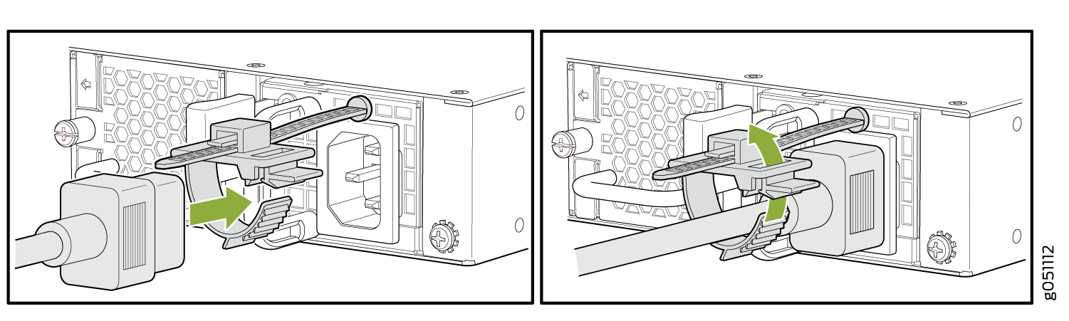 Figure 17: Connect Power Cord to an AC-Powered QFX5120-48T or QFX5120-48Y Switch
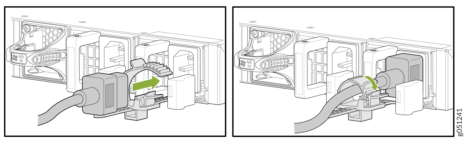
For QFX5120-48YM switches:
Gently lift the retainer clip up.
Insert the power cord coupler firmly into the inlet.
Push the retainer clip down until it is snug against the base of the coupler (see Figure 18).
Figure 18: Connect Power to an AC-Powered QFX5120-48YM Switch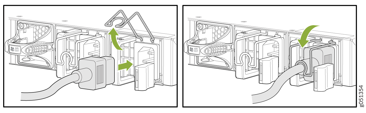
- If the AC power source outlet has a power switch, set it to the off
position.Note: The QFX5120 switch powers on as soon as power is provided to the power supply. QFX5120 does not have a power switch.
- Insert the power cord plug into an AC power source outlet.
- If the AC power source outlet has a power switch, set it to the on
position.
If you are connecting the power supply in a QFX5120-32C switch, verify that the LED on the power supply is lit green. If the LED is lit or blinking red, disconnect the power supply from the power source, and replace the power supply (see Maintain the QFX5120 Power System).
- If you are connecting the power supply in a QFX5120-48T, QFX5120-48Y, or QFX5120-48YM switch, verify that the AC and DC LEDs on the power supply are lit green. If the fault LED (!) is lit, disconnect the power supply from the power source, and replace the power supply (see Maintain the QFX5120 Power System).CAUTION:
Do not remove the power supply until you have a replacement power supply ready: you must install the replacement power supply within one minute after removing the failed power supply to ensure proper airflow and prevent chassis overheating.