Connecting the PTX5000 to AC Power
Tools and Parts Required to Provide AC Power to the PTX5000
If you have an AC-powered router, gather the tools required to connect the PTX5000 to AC power:
AC power cords
Phillips (+) screwdriver, number 2 to access the metal AC wiring compartment and remove or attach the AC power cord.
1/5-in. (5.5-mm) slotted screwdriver to attach the ground wire and input terminal wires of the AC power cord.
Connecting Power to the PTX5000 Three-Phase Delta AC PDUs
To connect the delta AC power cords to the three-phase delta AC PDUs (see Figure 7):
- Using a number 2 Phillips (+) screwdriver, remove the
four screws from the metal retaining bracket located on the lower
right of the PDU. Remove the metal retaining bracket from the PDU
(see Figure 1).Figure 1: Removing the Metal Retaining Bracket from a Three-Phase Delta AC PDU
- Unscrew the retaining nut from the AC power cord (see Figure 2 and Figure 3).Figure 2: Retaining Nut on a Three-Phase Delta AC Power Cord
 1—
1—Retaining nut
2—Three-phase delta AC power cord
Figure 3: Removing the Retaining Nut from a Three-Phase Delta AC Power Cord 1—
1—Retaining nut
2—Three-phase delta AC power cord
- Put the wires of the AC power cord through the hole of
the metal retaining bracket, and screw the retaining nut onto the
AC power cord to secure it to the metal retaining bracket (see Figure 4).Figure 4: Connecting the Metal Retaining Bracket to Three-Phase Delta AC Power Cord
 1—
1—Retaining nut
3—Three-phase delta AC power cord
2—Metal retaining bracket
- Using a number 2 Phillips (+) screwdriver, loosen the
two captive screws on the metal AC wiring compartment. Open the metal
door of the metal AC wiring compartment. Push the wires of the AC
power cord into the area for the metal retaining bracket, and pull
the wires to the left toward the metal AC wiring compartment. Using
a number 2 Phillips (+) screwdriver, use the four screws on the metal
retaining bracket to secure the AC power cord to the PDU (see Figure 5).Figure 5: Connecting Power to a Three-Phase Delta AC PDU
- Connect the wires to the AC terminal block on the three-phase
delta AC PDU (Figure 6). Using a 1/5-in. (5.5-mm) slotted screwdriver, loosen each
of the input terminals or grounding point screws, insert each wire
into the grounding point or input terminal, and tighten the screw.
- Insert the wire labeled GND into the grounding point.
- Insert the wire labeled L1 into the L1 input terminal.
- Insert the wire labeled L2 into the L2 input terminal.
- Insert the wire labeled L3 into the L3 input terminal.
Figure 6: Connecting Ground and Power to a Three-Phase Delta AC PDU
1 — Top installation handle | 5 — Circuit breaker |
2 — Front installation handle | 6 — Wiring compartment |
3 — Power OUTPUT switch | 7 — Wiring compartment door |
4 — Air exhaust ventilation | 8 — Metal retaining bracket |
Connecting Power to the PTX5000 Three-Phase Wye AC PDUs
To connect an AC power cord to a three-phase wye AC PDU (see Figure 14):
- Using a number 2 Phillips (+) screwdriver, loosen the
four captive screws that fasten the metal retaining bracket to the
PDU, and remove the metal retaining bracket from the PDU (see Figure 8).Figure 8: Removing the Metal Retaining Bracket from a Three-Phase Wye AC PDU
- Unscrew the retaining nut from the AC power cord (see Figure 9 and Figure 10).Figure 9: Retaining Nut on a Three-Phase Wye AC Power Cord1—
Retaining nut
2—Three-phase wye AC power cord
Figure 10: Removing the Retaining Nut from a Three-Phase Wye AC Power Cord1—Retaining nut
2—Three-phase wye AC power cord
- Put the wires of the AC power cord through the hole of
the metal retaining bracket, and screw the retaining nut onto the
AC power cord to secure it to the metal retaining bracket (see Figure 11).Figure 11: Connecting the Metal Retaining Bracket to the Three-Phase Wye AC Power Cord
 1—
1—Retaining nut
3—Three-phase wye AC power cord
2—Metal retaining bracket
- Using a number 2 Phillips (+) screwdriver, loosen the
two captive screws on the metal AC wiring compartment. Open the metal
door of the metal AC wiring compartment. Push the wires of the AC
power cord into the area for the metal retaining bracket, and pull
the wires to the left toward the metal AC wiring compartment. Using
a number 2 Phillips (+) screwdriver, use the four captive screws on
the metal retaining bracket to secure the AC power cord to the PDU
(see Figure 12).Figure 12: Connecting Power to a Three-Phase Wye AC PDU
- Connect the wires to the AC terminal block on the three-phase
wye AC power supply (Figure 13). Using a
1/5-in. (5.5-mm) slotted screwdriver, loosen each of the input terminals
or grounding point screws, insert each wire into the grounding point
or input terminal, and tighten the screw. Figure 13: Connecting Power to the Three-Phase Wye AC Power Supply
1 — Top installation handle | 5 — Circuit breaker |
2 — Front installation handle | 6 — Wiring compartment |
3 — Power OUTPUT switch | 7 — Wiring compartment door |
4 — Air exhaust ventilation | 8 — Metal retaining bracket |
Connecting Power to the PTX5000 High Capacity Delta AC PDUs
To connect an AC power cord to a High Capacity Delta AC PDU (see Figure 15):
1 — Top installation handle | 6 — Input voltage LED |
2 — Front installation handle | 7 — Wiring compartment |
3 — PDU OK LED | 8 — Power input cord selection switch |
4 — Power switch labeled (|) for the
on position and ( | 9 — Metal retaining bracket |
5 — Air exhaust ventilation | 10 — Wiring compartment door |
- Switch the power switch on the PDU faceplate to the standby
(
 ) position.
 - Using a number 2 Phillips (+) screwdriver, remove
the four screws from the metal retaining bracket located on the lower
right of the PDU. Remove the metal retaining bracket from the PDU
(see Figure 16).Figure 16: Removing the Metal Retaining Bracket from a High Capacity Delta AC PDU
- Unscrew the retaining nut from the AC power cord (see Figure 17 and Figure 18).Figure 17: Retaining Nut on an AC Power Cord1—
Retaining nut
2—AC power cord
Note:This is a representational image. The High Capacity Delta AC PDU supports three power cords for 60 A, 100 A, and 150 A, respectively.
Figure 18: Removing the Retaining Nut from an AC Power Cord1—Retaining nut
2—AC power cord
- Put the wires of the AC power cord through the hole of
the metal retaining bracket, and screw the retaining nut onto the
AC power cord to secure it to the metal retaining bracket (see Figure 19).Figure 19: Connecting the Metal Retaining Bracket to an AC Power Cord
 Note:
Note:If you are using 150 A power, you must use a metal bracket that is larger than the default metal bracket. This bracket is shipped along with the High Capacity Delta AC PDUs. Labels on top of the metal brackets specify the power cords that can be used for each bracket (see Figure 20). The installation procedure to connect the metal bracket to the PDU is the same for both metal brackets.
Figure 20: Metal Brackets for Power Cords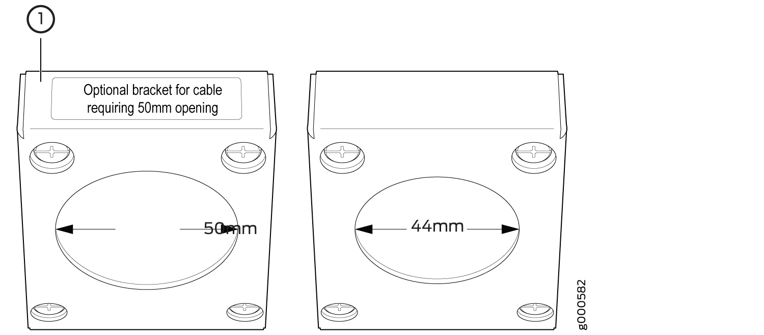 1—
1—Metal Bracket with label Use for 740-053918, 740-059634 Power Cords—740-053918 indicates the 100-A power cord and 740-059634 the 150-A power cord for the High Capacity Delta AC PDU.
2—Metal Bracket with label Use for 740-053919, 740-059635, 740-035459 Power Cords—740-053919 indicates the power cord for the High Capacity Delta AC PDU. 740-059635 indicates the 100-A power cord and 740-035459 the 60-A power cord.
- Attach the power cord to the PDU:
- Using a number 2 Phillips (+) screwdriver, loosen the two captive screws on the metal AC wiring compartment.
- Open the metal door of the metal AC wiring compartment.
- Push the wires of the AC power cord into the area for the metal retaining bracket, and pull the wires to the left toward the metal AC wiring compartment.
- Using a number 2 Phillips (+) screwdriver, use the four screws on the metal retaining bracket to secure the AC power cord to the PDU (see Figure 21).
Figure 21: Attaching the Power Cord to the High Capacity Delta AC PDU
- Connect the wires to the AC terminal block on the High
Capacity Delta AC PDU (Figure 22). Using
a 1/5-in. (5.5-mm) slotted screwdriver, loosen each of the input terminal
screws and the grounding point screw, insert each wire into the grounding
point or input terminal, and tighten the screw.
- Insert the wire labeled GND into the grounding point.
- Insert the wire labeled L1 into the L1 input terminal.
- Insert the wire labeled L2 into the L2 input terminal.
- Insert the wire labeled L3 into the L3 input terminal.
Figure 22: Connecting Ground and Power to a High Capacity Delta AC PDU
- Before you power on the PDU, select the switch setting
corresponding to the AC input power cord that is connected to the
PDU. Figure 23 shows an ampere switch,
located inside the wiring compartment.
If CBL-PTX-AC-D cable is used, set the switch to 60A.
If CBL2-PTX-100AC-D cable is used, set the switch to 100A.
If CBL2-PTX-150AC-D cable is used, set the switch to 150A.
You can verify the switch setting by using the
show chassis
environment pdu
command. The command displays the input power rating as shown in the following example:show chassis environment pdu 0
PDU 0 status:
State                      Online
BoostConv
               OK
Feed Switch                150Amps
                  <<<===
Hours Used
             142
Firmware Version (MCU1)    03.04
Figure 23: Ampere Switch Warning:
If you set the ampere switch in the wiring compartment incorrectly, the AC power cord might overheat. Setting the ampere switch incorrectly might also cause the site circuit breaker to trip.
Note:The system software gets the system power configuration from the PDU and displays it in the output of the
show chassis
environment pdu
command. Depending on the setting, the system software limits the system configuration (FPCs and PICs) to keep the power demand within the maximum output power available from the PDU.Note:In a redundant system with two PDUs, the PDUs share the load. If the ampere switch setting of one PDU is lower than the other, Junos OS reduces the rating of the other PDU to the lower value.
Connecting Power to the PTX5000 High Capacity Wye AC PDUs
To connect an AC power cord to a High Capacity Wye AC PDU (see Figure 24):
1 — Top Installation handle | 6 — Circuit breaker |
2 — Front installation handle | 7 — Input voltage LED |
3 — PDU OK LED | 8 — Wiring compartment |
4 — Power switch labeled (|) for the
on position and ( | 9 — Metal retaining bracket |
5 — Air exhaust ventilation | 10 — Wiring compartment door |
To connect an AC power cord to a High Capacity Wye AC PDU (see Figure 24):
- Move the power switch located on the faceplate of the
PDU to the standby () position.
- Using a number 2 Phillips (+) screwdriver, loosen
the four captive screws that fasten the metal retaining bracket to
the PDU, and remove the metal retaining bracket from the PDU (see Figure 25).Figure 25: Removing the Metal Retaining Bracket from a High Capacity Wye AC PDU
- Unscrew the retaining nut from the AC power cord (see Figure 26 and Figure 27).Figure 26: Retaining Nut on an AC Power Cord1—
Retaining nut
2—AC power cord
Figure 27: Removing the Retaining Nut from an AC Power Cord1—Retaining nut
2—AC power cord
- Put the wires of the AC power cord through the hole of
the metal retaining bracket, and screw the retaining nut onto the
AC power cord to secure it to the metal retaining bracket (see Figure 28).Figure 28: Connecting the Metal Retaining Bracket to the AC Power Cord1—
Retaining nut
3—AC power cord
2—Metal retaining bracket
- Attach the power cord to the PDU:
- Using a number 2 Phillips (+) screwdriver, loosen the two captive screws on the metal AC wiring compartment.
- Open the metal door of the metal AC wiring compartment.
- Push the wires of the AC power cord into the area for the metal retaining bracket, and pull the wires to the left toward the metal AC wiring compartment.
- Using a number 2 Phillips (+) screwdriver, use the four captive screws on the metal retaining bracket to secure the AC power cord to the PDU (see Figure 29).
Figure 29: Connecting Power to a High Capacity Wye AC PDU
- Connect the wires to the AC terminal block on the High
Capacity Wye AC PDU (see Figure 30). Using a 1/5-in.
(5.5-mm) slotted screwdriver, loosen each of the input terminal screws
and the grounding point screw, insert each wire into the grounding
point or input terminal, and tighten the screw. Figure 30: Connecting Power to the High Capacity Wye AC PDU
Connecting Power to the PTX5000 High Capacity Single-Phase AC PDUs
The high-capacity single-phase AC PDU accepts eight single-phase 30-A or eight single-phase 20-A, 200–250 VAC L-L input power. One 30-A or 20-A input power provides dedicated input power to each PSM.
To connect the AC power cords to the single-phase AC PDUs (see Figure 31):
- Move the power output switch on the PDU faceplate to the
standby () position.
- Using a number 2 Phillips (+) screwdriver, loosen the
screw on the 20-A input terminal and plug in the connector (see Figure 32 and Figure 33). Tighten the screw after plugging
in the connector. Note:
The 30-A connector does not have a clamp, but it has its own integral clip for locking the connector.
Figure 32: Plug Type for the 20-A Connector Figure 33: Connecting 20-A Inputs to a High Capacity Single-Phase AC PDU
- Connect up to eight inputs (20-A or 30-A) to the PDU.
See Figure 34 and Figure 35.Figure 34: Plug Types for the 30-A Connector
 Figure 35: Connecting 30-A Inputs to a High Capacity Single-Phase AC PDU