ON THIS PAGE
PTX12008 Cooling System
The PTX12008 has three fan trays.
The PTX12008 cooling system consists of three fan trays. They work together to keep all the components within the acceptable temperature range.
Fan Trays
Each fan tray contains five dual rotating fans, a non-removable control board, LEDs, and two handles on the front faceplate. The fans in the fan trays have n+1 redundancy─if one fan rotor fails, the remaining fans operate at a higher speed to maintain proper cooling.
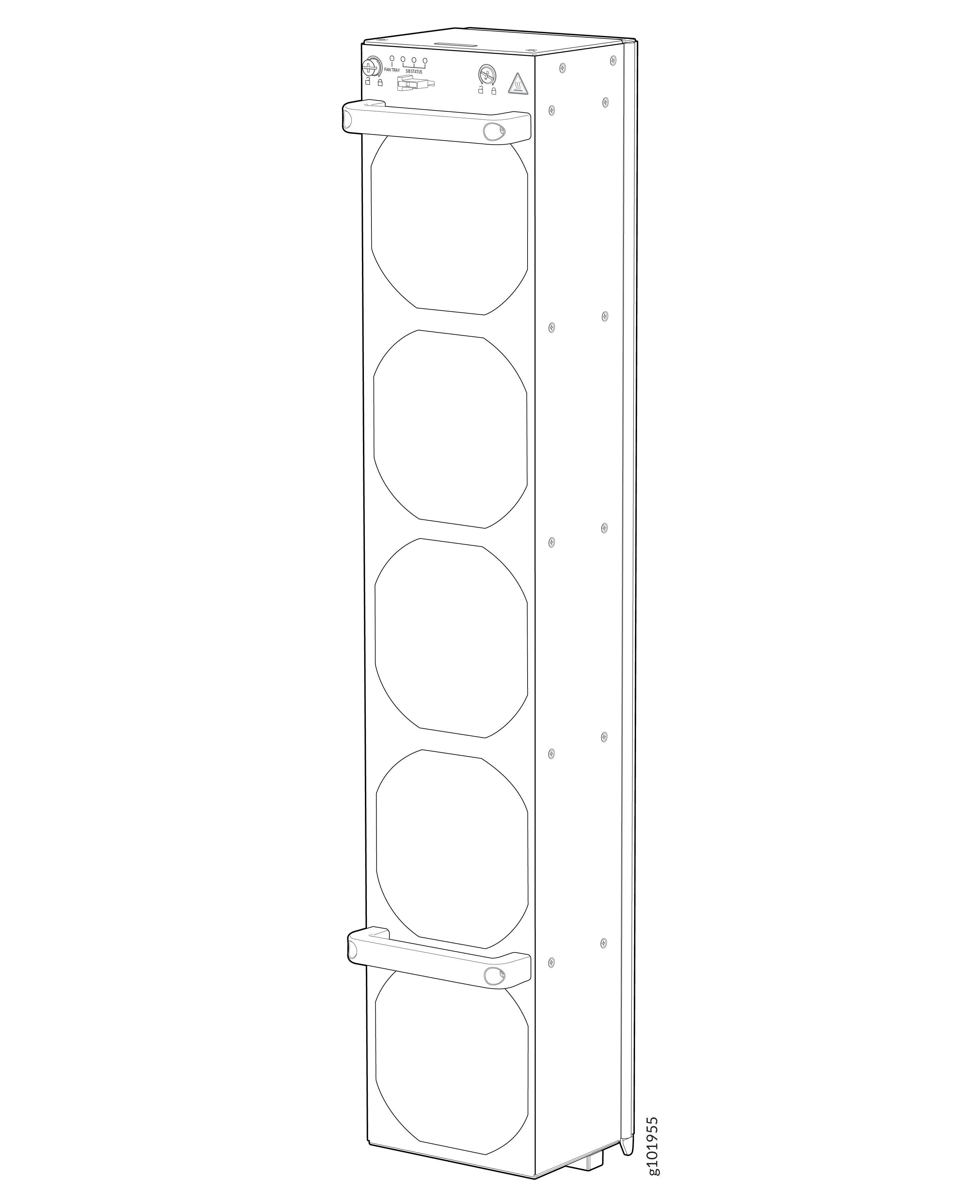
The fan trays are hot-insertable and hot-removable field-replaceable units (FRUs): You can remove and replace them without powering off the router or disrupting router functions.
You can install the fan trays in the fan tray slots on the rear panel of the chassis. The fan trays install vertically, side by side, below the power shelf.
In addition to the fans in the fan trays, there is an internal built-in fan in each power supply module (PSM) that helps to cool the PSM.
The system continuously monitors the temperature of critical parts across the chassis and adjusts the chassis fan speed according to the temperature. The Junos OS Evolved controls the fan speed. Under normal operating conditions, the fans in the fan trays run at less than full speed. If one fan tray fails or appears missing (such as when a SIB is being replaced), the other fan trays set the fans to full speed. This behavior ensures that the router continues to operate normally as long as the remaining fans cool the chassis sufficiently. Use the show chassis fan command to see the status of individual fans and fan speed. If the maximum temperature specification is exceeded and the system cannot be adequately cooled, the Routing and Control Board shuts down some or all of the hardware components.
See Table 1 for the specifications of the fan trays.
| Specification | Value |
|---|---|
|
Number of fans per fan tray |
5 |
|
Number of fans per chassis |
15 |
|
Fan numbering |
0 through 4 |
|
Volume flow per chassis at 100% fan speed at 77 °F (25 °C) |
3170 cubic feet per minute (CFM) when AC/HVAC/HVDC PSMs are installed in all the PSM slots 3350 CFM when DC PSMs are installed in all the PSM slots |
|
Volume flow of the power shelf at 100% fan speed at 77 °F (25 °C) with AC/HVAC/HVDC PSMs installed in all the PSM slots |
320 CFM |
|
Volume flow of the power shelf at 100% fan speed at 77 °F (25 °C) with DC PSMs installed in all the PSM slots |
500 CFM |
|
Height |
27.55 in. (69.98 cm) |
|
Width |
5.04 in. (12.8 cm) |
|
Depth |
4.3 in. (10.9 cm) not including handles; 5.5 in. (14 cm) including handles |
|
Weight |
19.3 lb (8.8 kg) |
Airflow
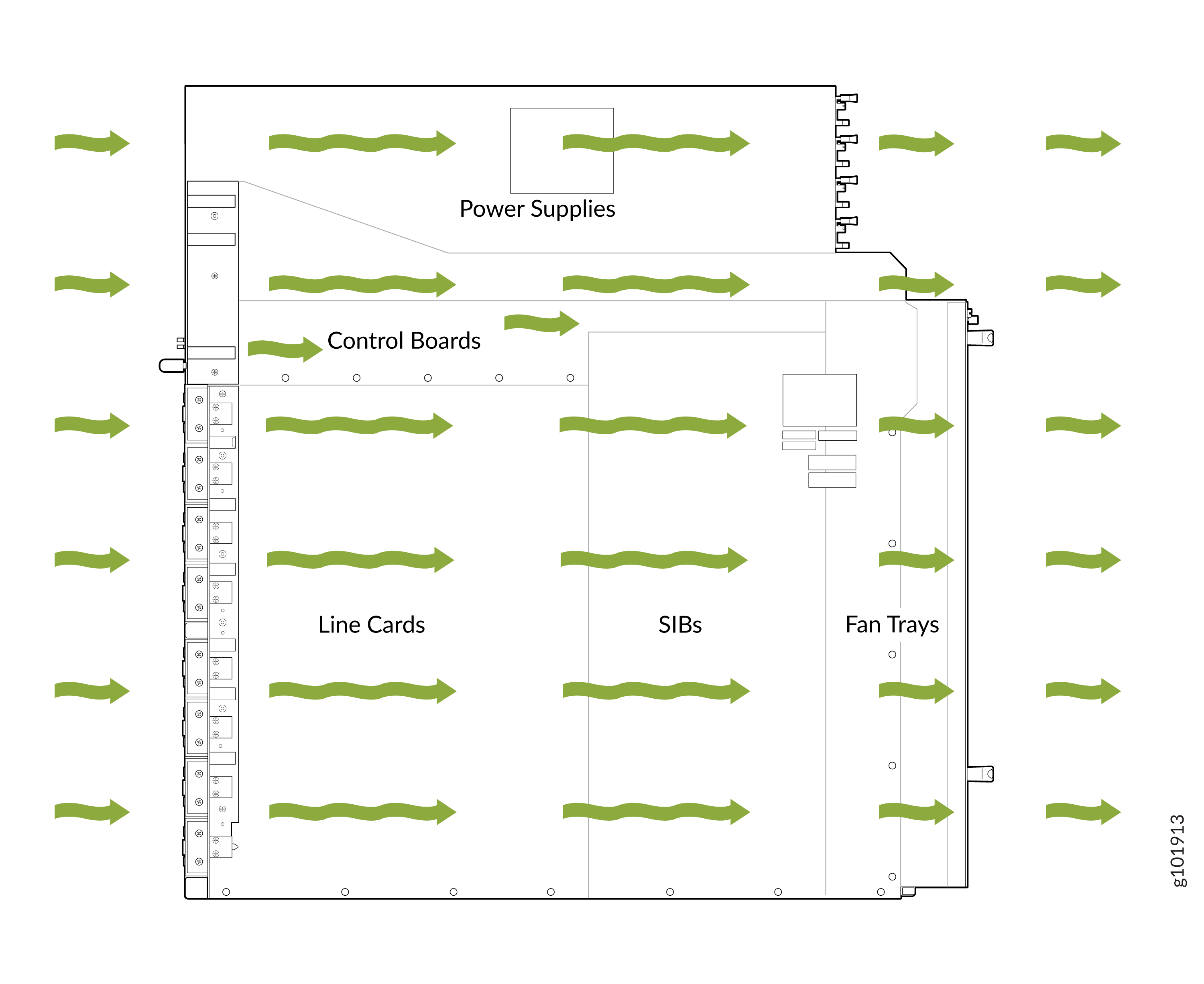
The PTX12008 has a front-to-back cooling system. Air flows into the chassis from the ports in the Flexible PIC Concentrators (FPCs) and Routing and Control Boards (RCBs) installed on the front panel of the chassis, passes through the Switch Interface Boards (SIBs), and exits from the fan trays and the PSMs installed on the rear panel of the chassis.
Fan Tray and SIB Status LEDs
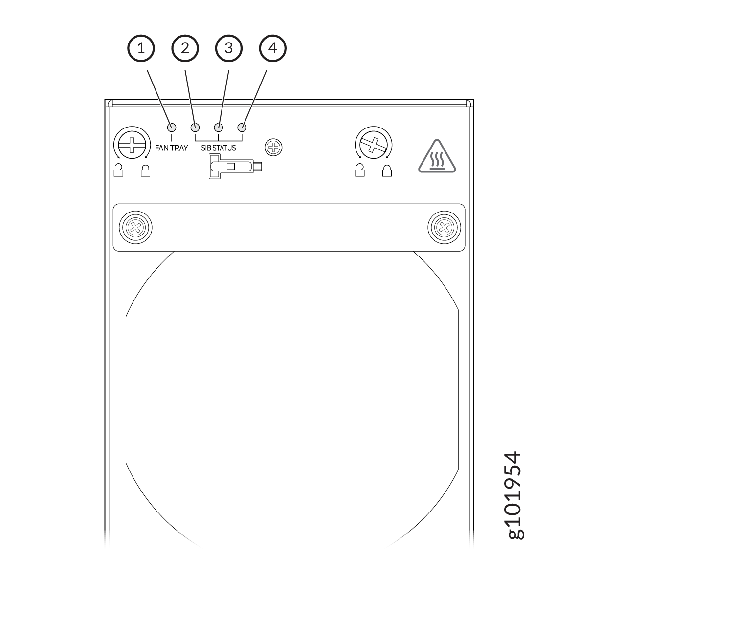
Each fan tray has one LED labeled FAN TRAY and three LEDs collectively labeled SIB STATUS. The FAN TRAY LED represents the status of the fans in the fan tray. The SIB STATUS LEDs represent the status of the Switch Interface Boards (SIBs) installed behind the fan tray. The LEDs are located in the top-left corner of the fan tray.
1 — Fan status LED | 3 — SIB status LED for SIB 3 through SIB 5 |
2 — SIB status LED for SIB 0 through SIB 2 | 4 — SIB status LED for SIB 6 through SIB 8 |
|
Name |
Color |
State |
Description |
|---|---|---|---|
|
FAN (Fan status) |
Green |
On steadily |
All the fans are operating normally. The system has verified that the fan tray is engaged, that the airflow is in the correct direction, and that all the fans are operating correctly. |
| Green | Blinking | The fans are starting up, but are not completely ready. | |
|
Yellow |
Blinking |
An error is detected in one or more fans in the fan tray. Replace the fan tray as soon as possible. Either the fan has failed or it has become disconnected. To maintain proper airflow through the chassis, leave the fan tray installed in the chassis until you are ready to replace it. |
|
|
None |
Off |
The fan is not receiving power from the fan tray. |
|
|
SIB Status (SIB 0 status) |
Green |
On steadily |
The left-most SIB in the chassis is online. |
|
Green |
Blinking |
The left-most SIB in the chassis is powering up. |
|
|
Yellow |
Blinking |
An error is detected in SIB 0. Replace the SIB as soon as possible. The SIB is located behind the left fan tray and is the left-most SIB in the chassis. To maintain proper airflow through the chassis, leave the fan tray installed in the chassis until you are ready to replace the SIB. |
|
|
None |
Off |
The SIB is offline. |
|
|
SIB Status (SIB 1 status) |
Green |
On steadily |
The center SIB behind the left fan tray is online. |
|
Green |
Blinking |
The center SIB behind the left fan tray is powering up. |
|
|
Yellow |
Blinking |
An error is detected in SIB 1. Replace the SIB as soon as possible. The SIB is located behind the left fan tray and is the SIB in the middle in the group of three SIBs. To maintain proper airflow through the chassis, leave the fan tray installed in the chassis until you are ready to replace the SIB. |
|
|
None |
Off |
The SIB is offline. |
|
|
SIB Status (SIB 2 status) |
Green |
On steadily |
The right-most SIB behind the fan tray on the left is online. |
|
Green |
Blinking |
The right-most SIB behind the fan tray on the left is powering up. |
|
|
Yellow |
Blinking |
An error is detected in SIB 2. Replace the SIB as soon as possible. The SIB is located behind the fan tray on the left and is the right-most SIB in the group of three SIBs. To maintain proper airflow through the chassis, leave the fan tray installed in the chassis until you are ready to replace the SIB. |
|
|
None |
Off |
The SIB is offline. |
|
|
SIB Status (SIB 3 status) |
Green |
On steadily |
The left-most SIB behind the fan tray in the middle is online. |
|
Green |
Blinking |
The left-most SIB behind the fan tray in the middle is powering up. |
|
|
Yellow |
Blinking |
An error is detected in SIB 3. Replace the SIB as soon as possible. The SIB is located behind the fan tray in the middle and is the left-most SIB in the group of three SIBs. To maintain proper airflow through the chassis, leave the fan tray installed in the chassis until you are ready to replace the SIB. |
|
|
None |
Off |
The SIB is offline. |
|
|
SIB Status (SIB 4 status) |
Green |
On steadily |
The center SIB behind the fan tray in the middle is online. |
|
Green |
Blinking |
The center SIB behind the fan tray in the middle is powering up. |
|
|
Yellow |
Blinking |
An error is detected in SIB 4. Replace the SIB as soon as possible. The SIB is located behind the fan tray in the middle and is the SIB in the middle in the group of three SIBs. To maintain proper airflow through the chassis, leave the fan tray installed in the chassis until you are ready to replace the SIB. |
|
|
None |
Off |
The SIB is offline. |
|
|
SIB Status (SIB 5 status) |
Green |
On steadily |
The right-most SIB behind the fan tray in the middle is online. |
|
Green |
Blinking |
The right-most SIB behind the fan tray in the middle is powering up. |
|
|
Yellow |
Blinking |
An error is detected in SIB 5. Replace the SIB as soon as possible. The SIB is located behind the fan tray in the middle and is the right-most SIB in the group of three SIBs. To maintain proper airflow through the chassis, leave the fan tray installed in the chassis until you are ready to replace the SIB. |
|
|
None |
Off |
The SIB is offline. |
|
|
SIB Status (SIB 6 status) |
Green |
On steadily |
The SIB on the left among the SIBs behind the fan tray on the right is online. |
|
Green |
Blinking |
The SIB on the left among the SIBs behind the fan tray on the right is powering up. |
|
|
None |
Off |
The SIB is offline. |
|
|
Yellow |
Blinking |
An error is detected in SIB 6. Replace the SIB as soon as possible. The SIB is located behind the fan tray on the right and is the SIB on the left in the group of two SIBs. To maintain proper airflow through the chassis, leave the fan tray installed in the chassis until you are ready to replace the SIB. |
|
|
SIB Status (SIB 7 status) |
Green |
On steadily |
The right SIB behind the fan tray on the right is online. |
|
Green |
Blinking |
The right SIB behind the fan tray on the right is powering up. |
|
|
Yellow |
Blinking |
An error is detected in SIB 7. Replace the SIB as soon as possible. The SIB is located behind the fan tray on the right and is the SIB in the middle in the group of three SIBs. To maintain proper airflow through the chassis, leave the fan tray installed in the chassis until you are ready to replace the SIB. |
|
|
None |
Off |
The SIB is offline. |
|
|
SIB Status (SIB 8 status) |
Green |
On steadily |
The right-most SIB behind the fan tray on the right is online. |
|
Green |
Blinking |
The right-most SIB behind the fan tray on the right is powering up. |
|
|
Yellow |
Blinking |
An error is detected in SIB 8. Replace the SIB as soon as possible. The SIB is located behind the fan tray on the right and is the SIB on the right in the group of three SIBs. To maintain proper airflow through the chassis, leave the fan tray installed in the chassis until you are ready to replace the SIB. |
|
|
None |
Off |
The SIB is offline. |