Install and Maintain the Front Door and its Components on the PTX10008 Router
The front door is required on the PTX10008 to protect fiber-optic cabling and to provide additional protection from electromagnetic interference (EMI). You can install the front door with or without the optional cable management system.
The PTX10008 supports two types of front doors:
- The door with the part number JNP10008-FRNT-PNL that supports side EMI deflectors.
- The door with the part number JNP10008-FRPNL1 that supports side EMI deflectors and an air filter.
Install the Front Door on the PTX10008 Router
Before you install the front door, ensure that you have the following tools and parts available:
-
A Phillips (+) screwdriver, number 2
-
Front door and side EMI deflectors (provided in the front door kit)
-
Base bracket set (two base brackets—one right base bracket and one left base bracket; provided)
-
Latch bracket set (two latch brackets—one right latch bracket and one left latch bracket; provided)
-
Eight Phillips flat-head mounting screws (provided in the front door kit)
-
An Electrostatic discharge (ESD) grounding strap (provided in the accessory kit)
-
(For JNP10008-FRPNL1) Three cable seals—Two cable seals for the right side and one cable seal for the left side (provided in the front door kit)
-
(For JNP10008-FRPNL1) Air filter (provided in the front door kit)
To install the front door:
-
Wrap and fasten one end of the ESD grounding strap around your bare wrist
and connect the other end of the strap to the ESD point on the front of the
chassis. See Figure 1.
Figure 1: ESD Point on the Front of the Chassis
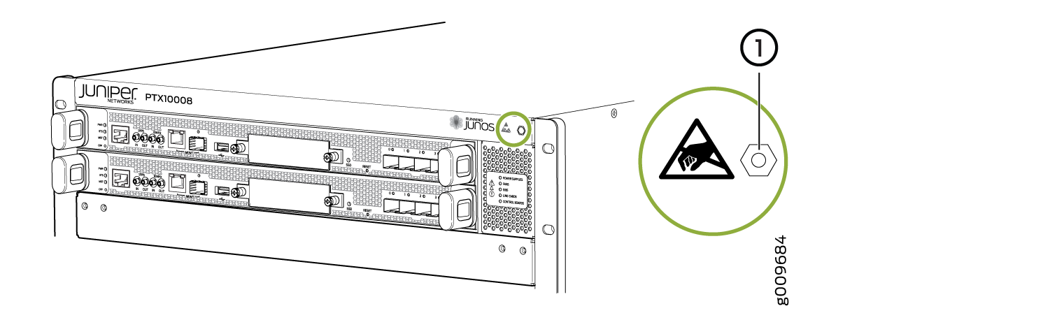 1—
1—ESD point
-
Remove the plastic bag that is taped to the front door. This bag holds the
latch brackets, base brackets, and screws. See Figure 2. The base
brackets are larger than the latch brackets.
Figure 2: Front Door Mounting Brackets
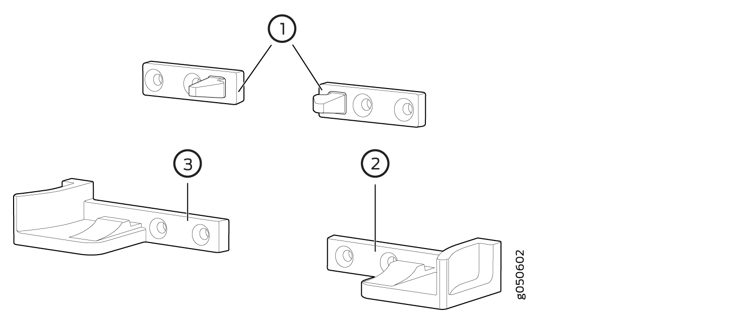 1—
1—Latch brackets
3—Left base bracket
2—Right base bracket
-
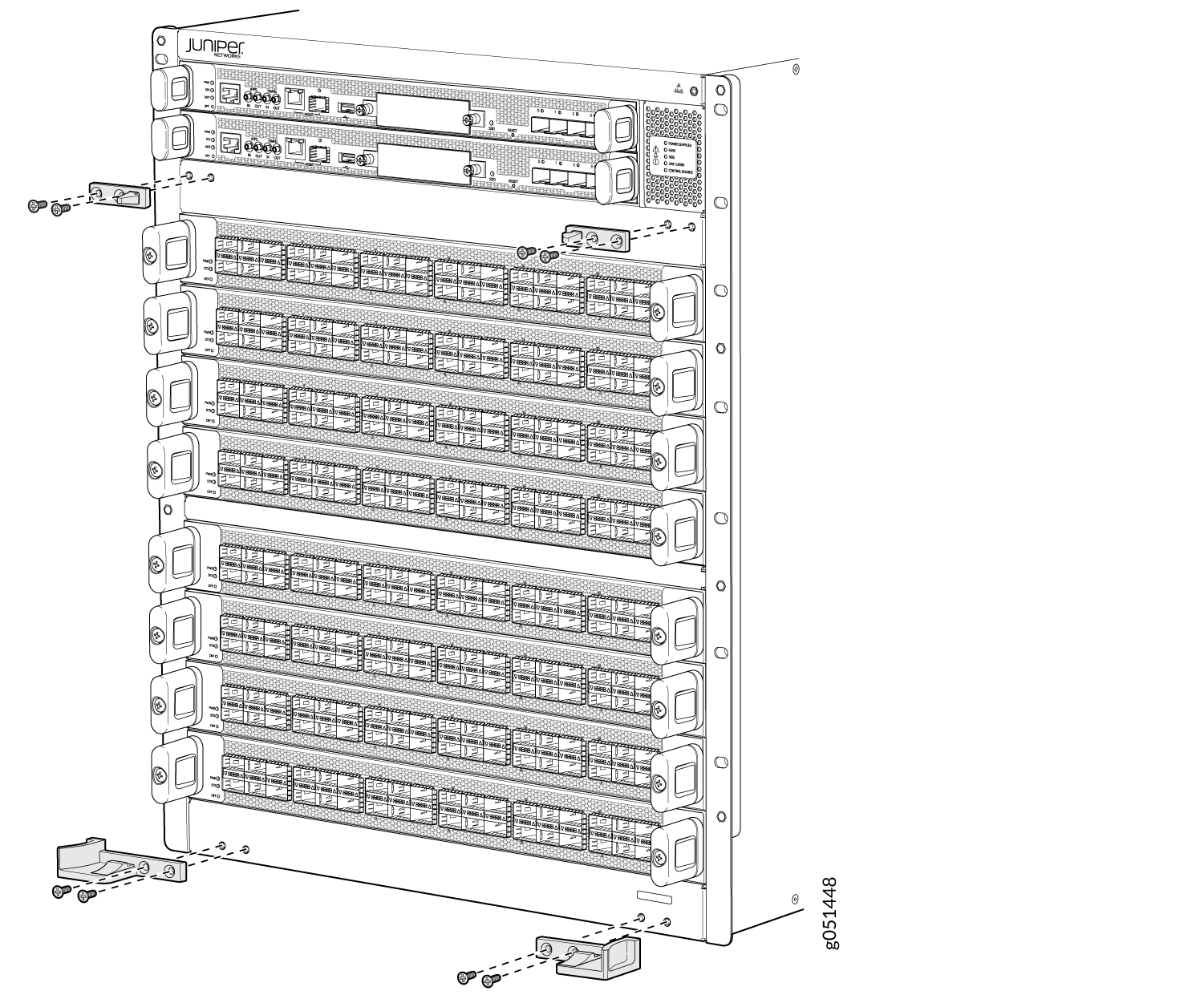
Attach the right and left base brackets to the bottom front of the chassis.
Attach the two latch brackets to the chassis. Screw holes are located for
each latch bracket between the top line card slot and the Routing and
Control Boards (RCBs). Use the Phillips screwdriver to attach the base
brackets to the lower front of the chassis using four of the supplied
flat-head screws. See Figure 3.
Figure 3: Attach Base and Latch Brackets
-
Install the cable seals.
-
Position the keyhole slots of one of the long cable seals over the
mounting screws. The long cable seals are not interchangeable; there
is a right cable seal and a left cable seal. Install the cable seals
so that the keyhole slots are on the inside, next to the line card.
See Figure 4.
Figure 4: Install the Cable Seals
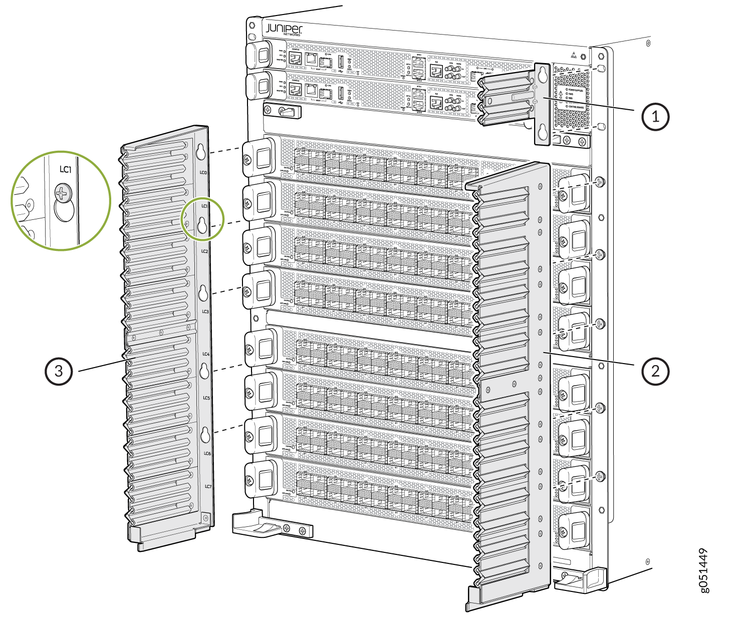 1—
1—RCB cable seal, install on the right of the RCB
3—Left cable seal
2—Right cable seal
-
Position the keyhole slots of one of the long cable seals over the
mounting screws. The long cable seals are not interchangeable; there
is a right cable seal and a left cable seal. Install the cable seals
so that the keyhole slots are on the inside, next to the line card.
See Figure 4.
-
Tilt the door toward the chassis until it is vertical with the chassis. The
release buttons on the side of the door allow the door to latch into place.
See Figure 5 for
JNP10008-FRNT-PNL front door or Figure 6 for
JNP10008-FRPNL1 front door.
Figure 5: Attach the JNP10008-FRNT-PNL Front Door
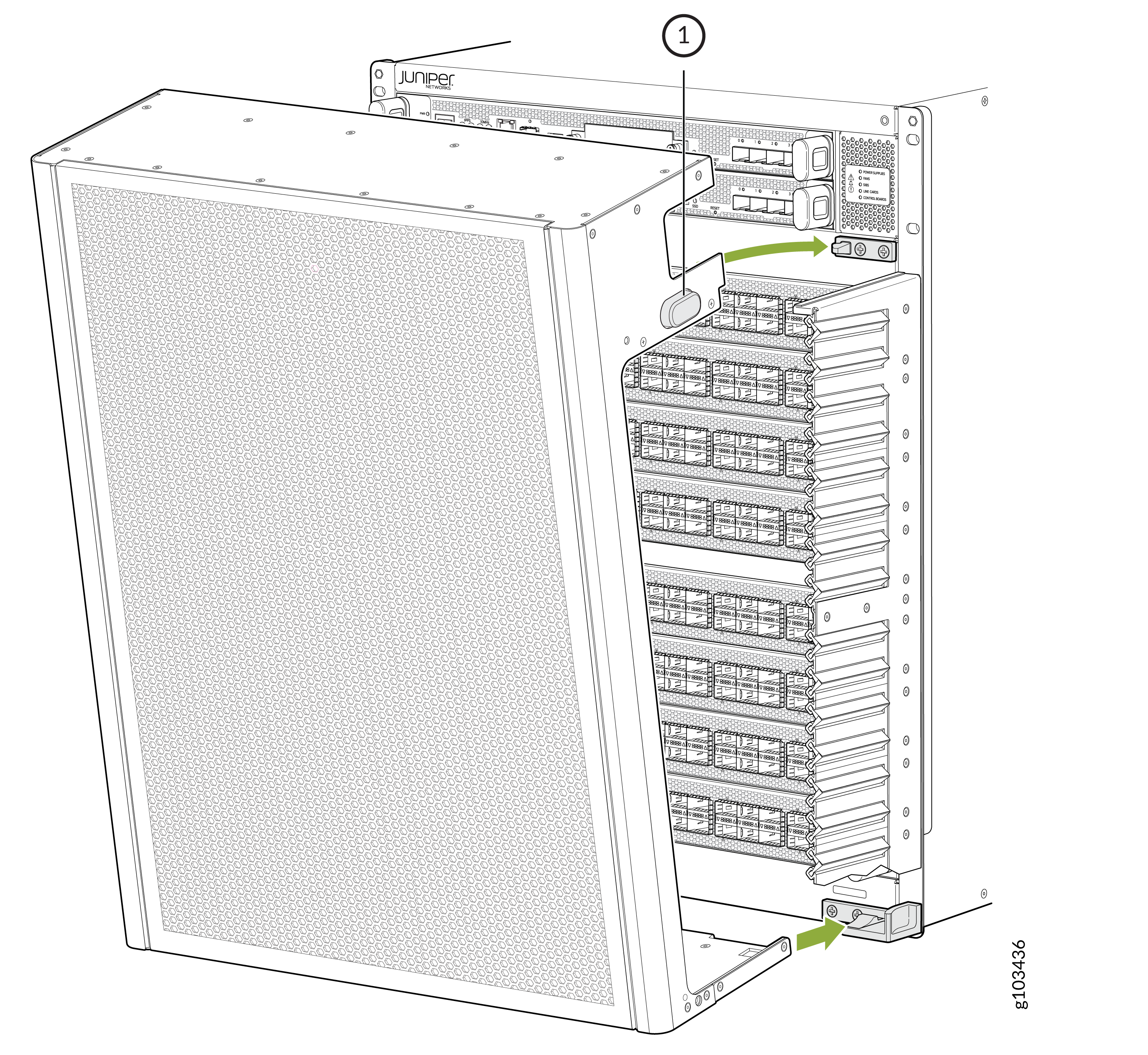 1—
1—Release button
Figure 6: Attach the JNP10008-FRPNL1 Front Door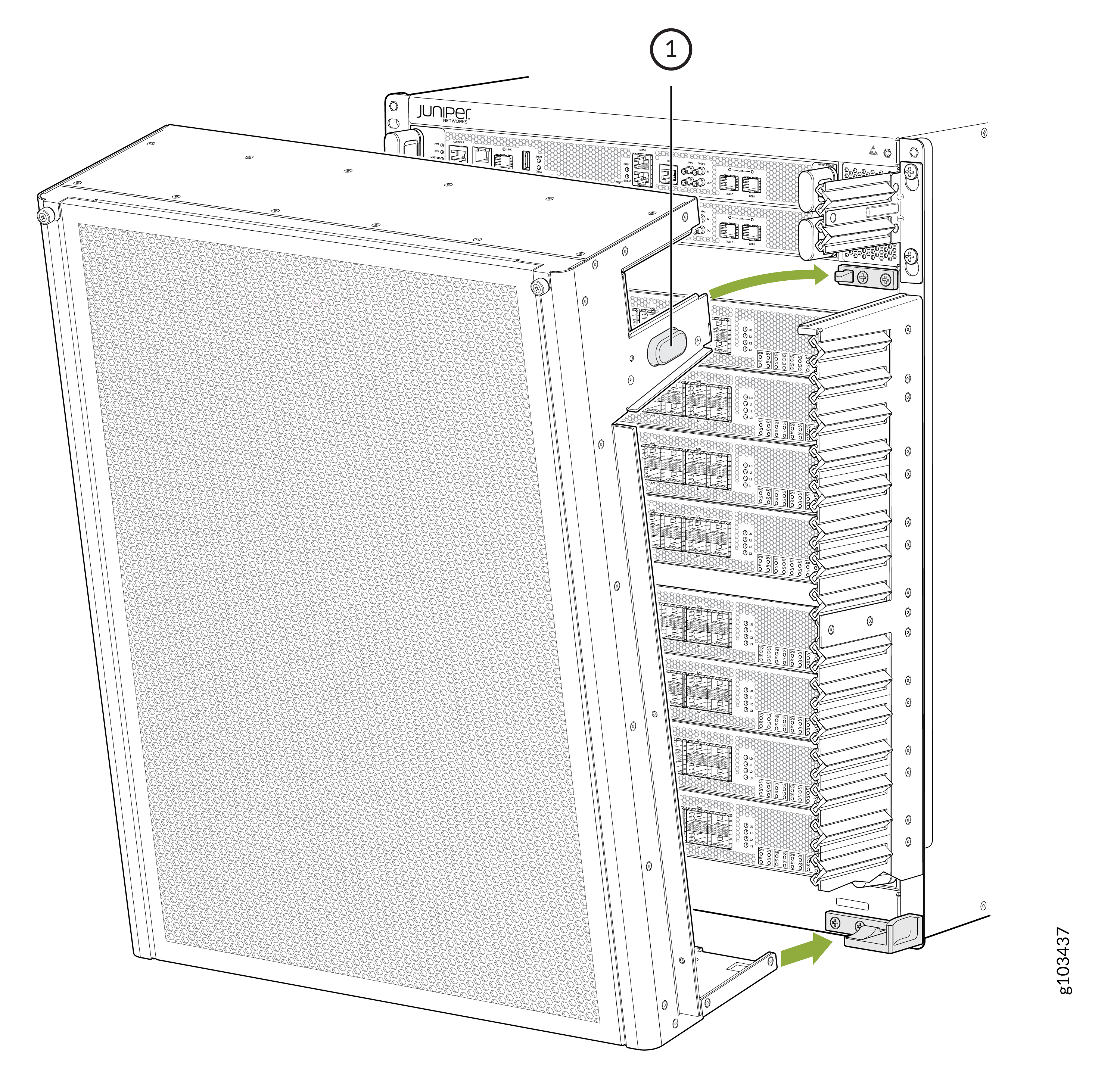 1—
1—Release button
-
Install the side EMI deflectors.
Note:
There are mounting points to attach the side EMI deflectors on JNP10008-FRNT-PNL and three mounting points to attach the side EMI deflectors on JNP10008-FRPNL1.
- Align the knobs of the right side EMI deflector over the mounting holes on the right side of the front door. Turn the knobs clockwise to fasten the side EMI deflector to the front door. See Figure 7 for JNP10008-FRNT-PNL or Figure 8 for JNP10008-FRPNL1.
- Repeat the step to install the other side EMI deflector on the left side of the front door.
Figure 7: Install the Side EMI Deflectors on JNP10008-FRNT-PNL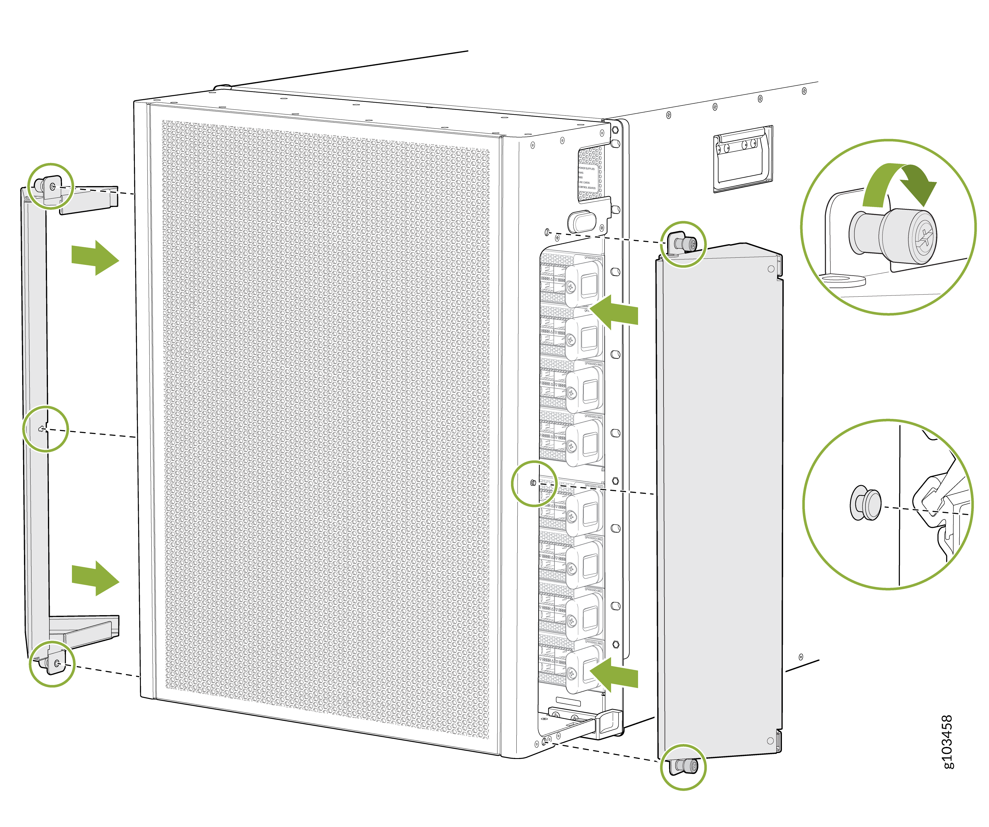 Figure 8: Install the Side EMI Deflectors on JNP10008-FRPNL1
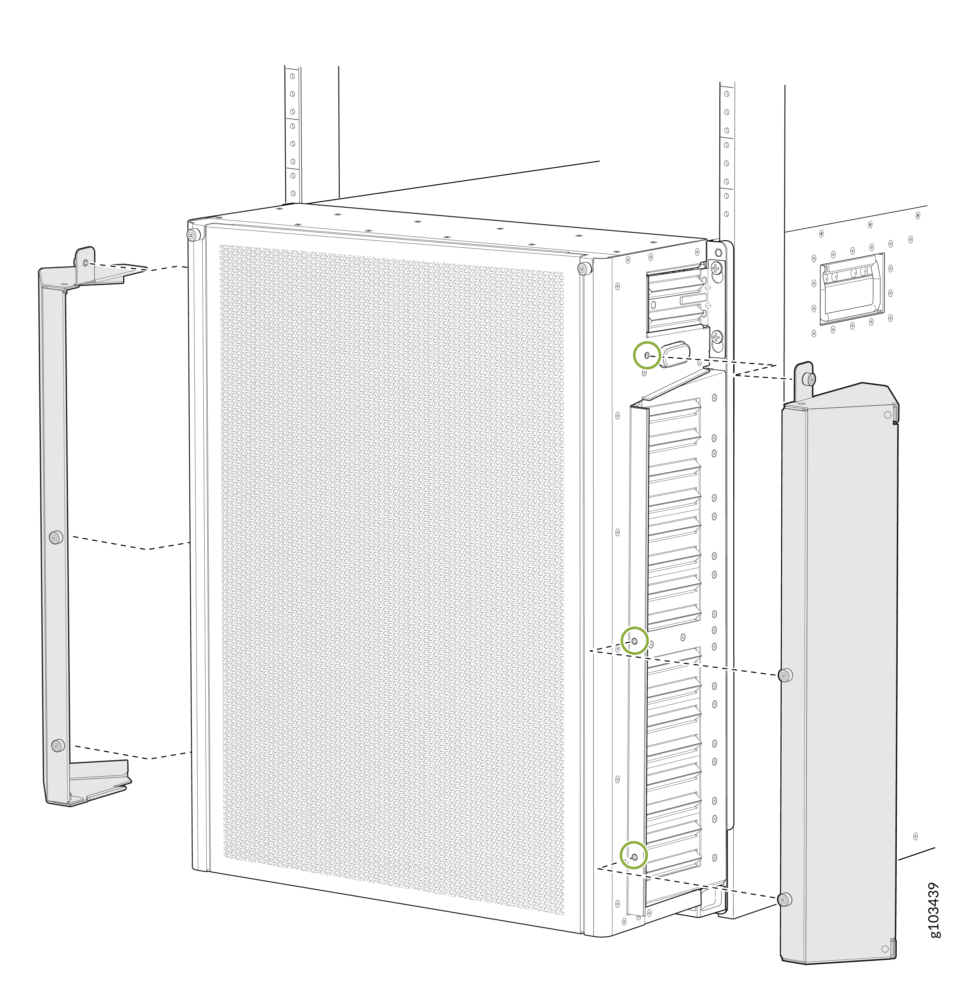
Install the Air Filter in the JNP10008-FRPNL1 Front Door
The JNP10008-FRPNL1 front door supports an air filter to keep the dust away from the chassis. You must replace the air filter every 6 months.
The maximum supported temperature for normal operation must be lower by 3° C when the air filter is at the end of its life.
Before you install the air filter on the front door:
-
Ensure that you have followed all safety warnings and cautions.
-
Ensure you understand how to prevent ESD damage. See Prevention of Electrostatic Discharge Damage.
-
Ensure that you have the following parts and tools available:
-
An ESD grounding strap (provided in the accessory kit)
-
Phillips (+) screwdriver, number 2
-
To install the air filter:
-
Turn the thumbscrews of the air filter frame anti-clockwise and flip the
air filter frame over to expose the air filter slot. See Figure 9.
Figure 9: Air Filter Slot in the JNP10008-FRPNL1 Front Door
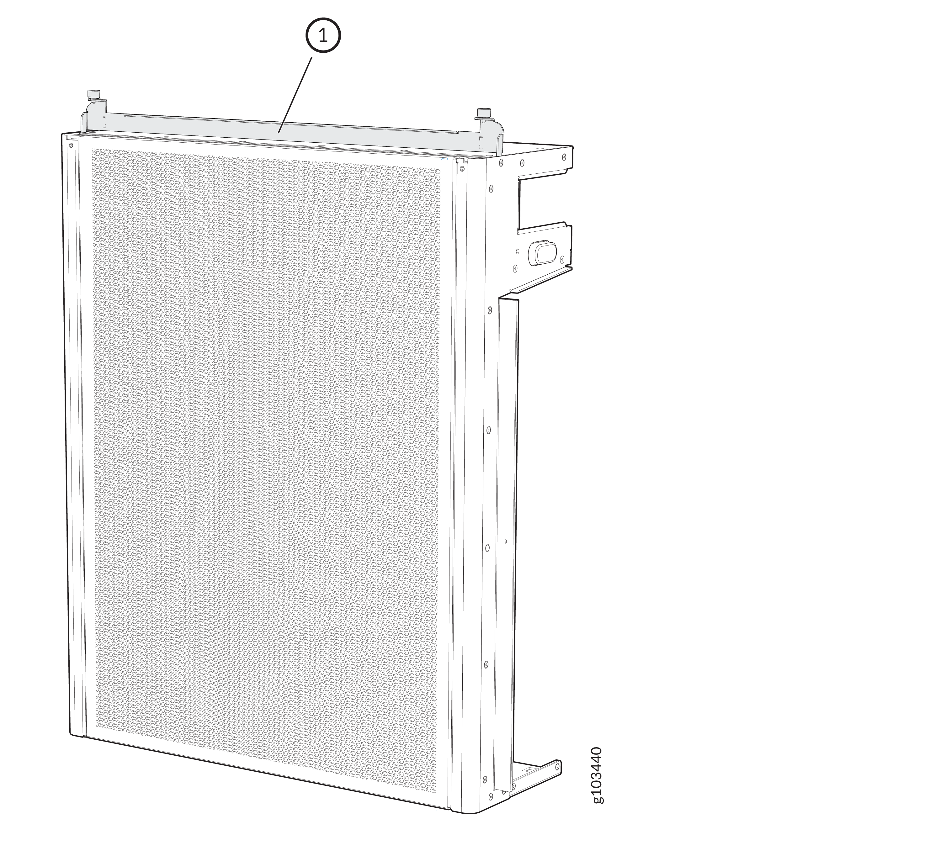 1—
1—Air filter frame
CAUTION:We recommend that you install the air filter to prevent harmful debris from entering the chassis.
-
Hold the air filter with both hands and insert it into the front door until
it stops. See Figure 10.
Figure 10: Insert the Air Filter into the JNP10008-FRPNL1 Front Door
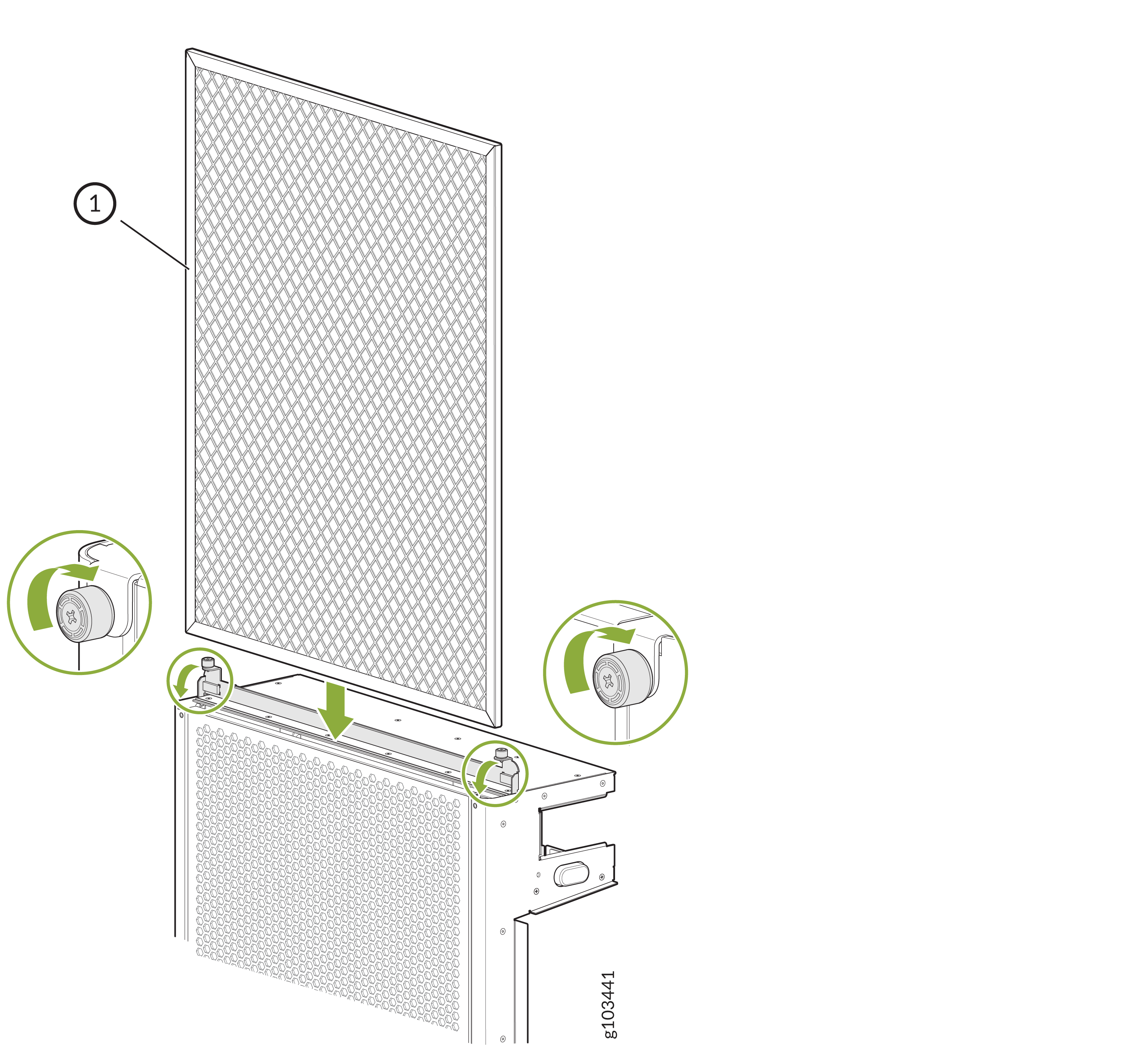 1—
1—Air filter
Remove the Air Filter from the JNP10008-FRPNL1 Front Door
Before you remove the air filter from the front door:
-
Ensure that you have followed all safety warnings and cautions.
-
Ensure you understand how to prevent ESD damage. See Prevention of Electrostatic Discharge Damage.
-
Ensure that you have the following parts and tools available:
-
An ESD grounding strap
-
Phillips (+) screwdriver, number 2
-
To remove the air filter:
-
Turn the thumbscrew on the air filter frame anti-clockwise and flip the
frame open to expose the air filter (see Figure 9).
Figure 11: Expose the Air Filter in the JNP10008-FRPNL1 Front Door
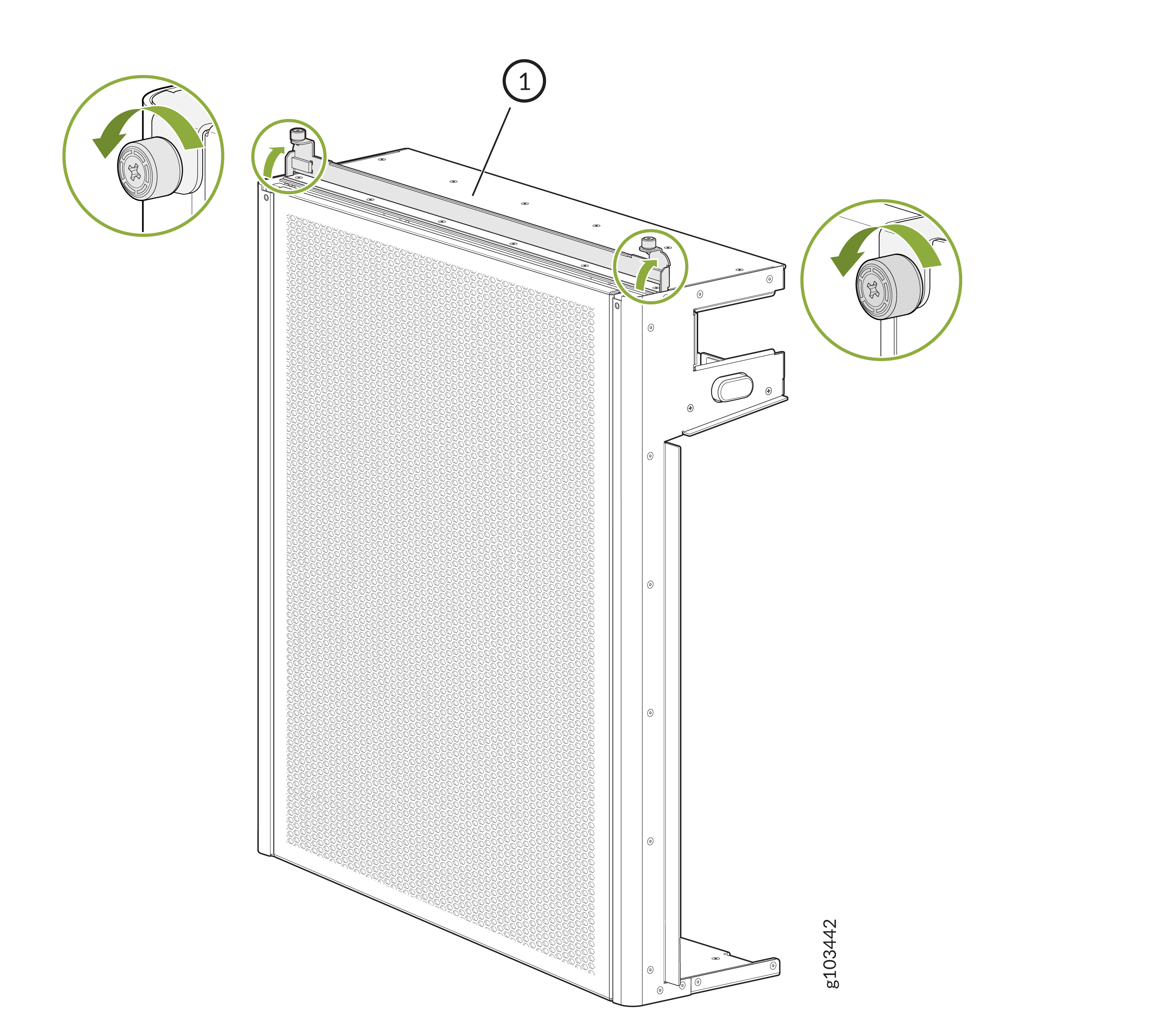 1—
1—Air filter frame
-
Grasp the air filter with both hands and lift it straight up and out of the
front door (see Figure 12).
Figure 12: Remove the Air Filter from the JNP10008-FRPNL1 Front Door
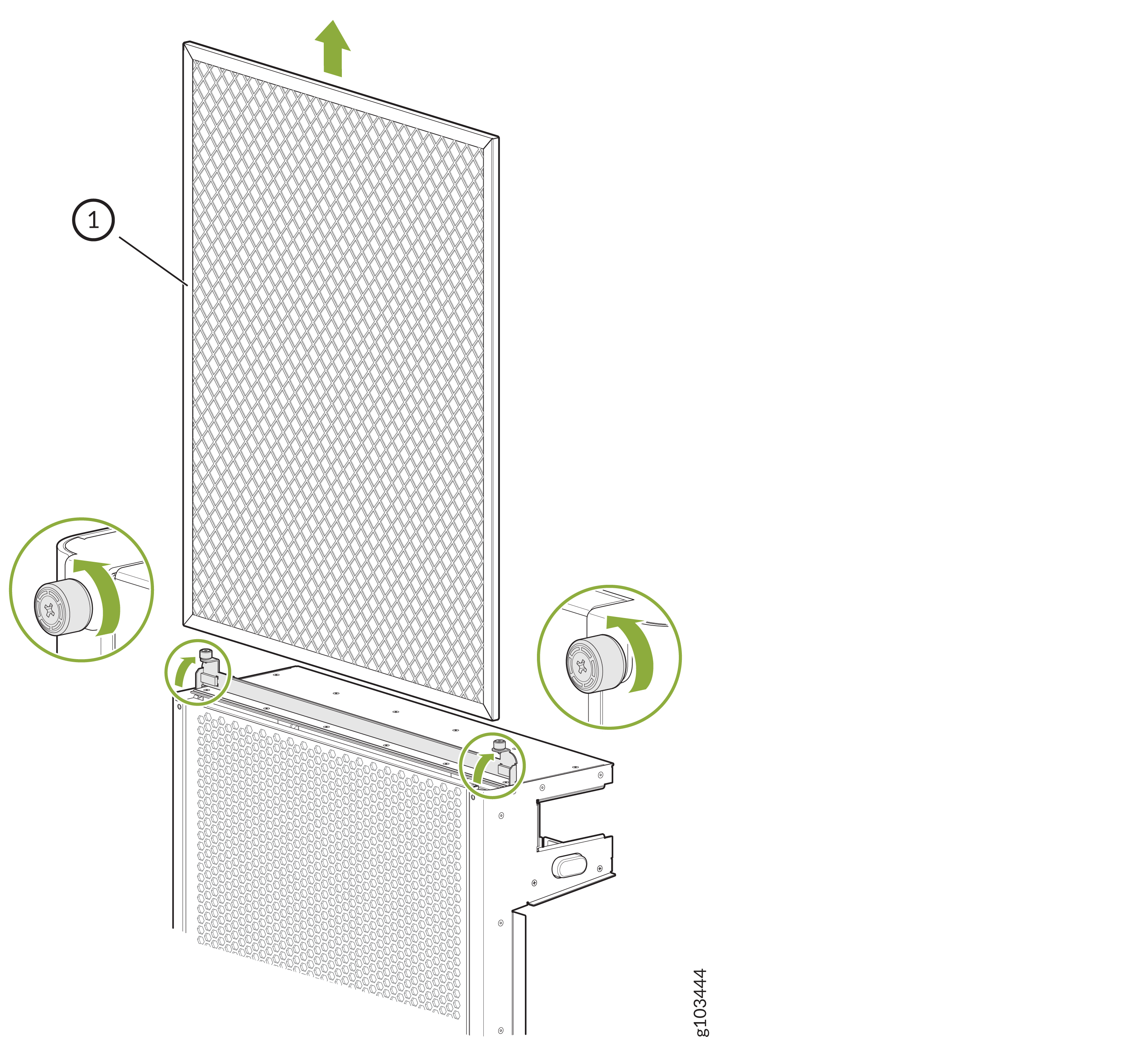 1—
1—Air filter
Remove the Side EMI Deflectors from the Front Door
Before you remove the side EMI deflectors on the front door:
-
Ensure that you have followed all safety warnings and cautions.
-
Ensure you understand how to prevent ESD damage. See Prevention of Electrostatic Discharge Damage.
-
Ensure that you have the following parts and tools available:
-
An ESD grounding strap (provided in the accessory kit)
-
Phillips (+) screwdriver, number 2
-
An antistatic mat or an antistatic bag
-
To remove a side EMI deflector from the front door:
- Loosen the captive screws on the side EMI deflector by using the screwdriver.
- Gently pull the side EMI deflector away from the door and place it on an antistatic mat or in an antistatic bag.
Remove the Front Door from the PTX10008 Router
Before you remove the front door, ensure that you have the following tools and parts:
-
An Electrostatic discharge (ESD) grounding strap
-
An antistatic mat or an antistatic bag to keep the door
To remove the front door:
-
Press the latch button to disengage the door (see Figure 13) and gently
pull the top of the door away from the chassis. The illustration shows the
door with the part number JNP10008-FRNT-PNL. The procedure is the same for
the door with the part number JNP10008-FRPNL1.
Figure 13: Remove the Front Door from the PTX10008 Chassis
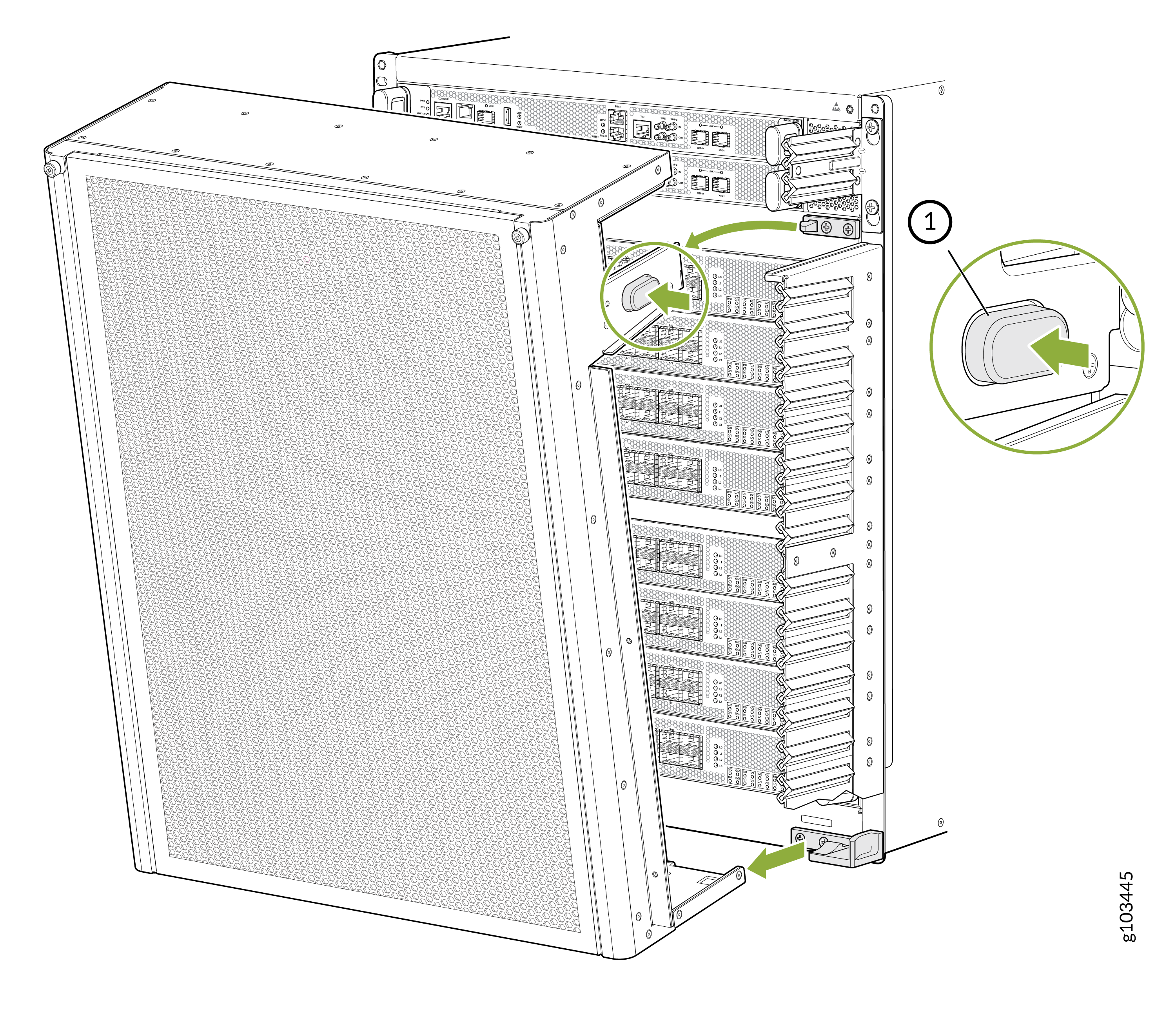 1—
1—Latch button