Connect the PTX10004 to External Devices
You can manage the PTX10004 router by using the two management ports on the Routing and Control board (RCB) for out-of-band management or through the console port on the RCB. To connect a PTX10004 router to external management devices, read to the following sections.
Connect a PTX10004 Router to a Network for Out-of-Band Management
Ensure that you have an appropriate cable available. See Management Port Connector Pinouts for the PTX10004 and Connect a PTX10004 Router to a Management Console.
You can monitor and manage a PTX10004 using a dedicated management channel. Each PTX10004 RCB has two management ports: a 10/100/1000BASE-T RJ-45 port for copper connections and a 1GbE small form-factor pluggable (SFP) port for fiber connections. Use the management ports to connect the RCB to a network for out-of-band management.
You cannot use the management ports to perform the initial configuration of the PTX10004. You must configure the management ports before you can successfully connect to the PTX10004 using these ports. See Perform the Initial Configuration for the PTX10004.
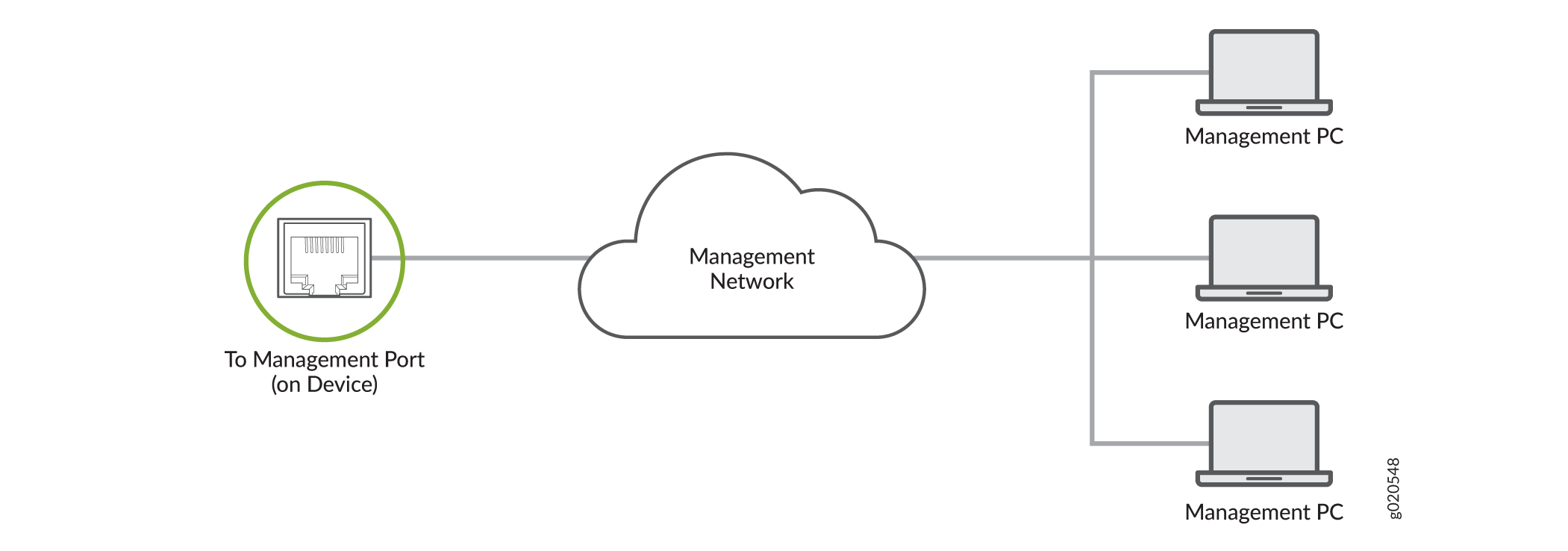
To connect a PTX10004 to a network for out-of-band management (see Figure 1):
- Connect one end of the cable to one of the two management ports (labeled MGNT) on one of the RCBs.
- Connect the other end of the cable to the management router.
Connect a PTX10004 Router to a Management Console
Ensure that you have an RJ-45 to DB-9 rollover cable available.
If your laptop or PC does not have a DB-9 connector pin (plug) and you want to connect your laptop or PC directly to the PTX10004 router, use a combination of the RJ-45 to DB-9 cable and a USB to DB-9 plug adapter. You must provide the USB to DB-9 plug adapter.
We no longer include the RJ-45 console cable with the DB-9 adapter as part of the device package. If the console cable and adapter are not included in your device package, or if you need a different type of adapter, you can order the following separately:
-
RJ-45 to DB-9 adapter (JNP-CBL-RJ45-DB9)
-
RJ-45 to USB-A adapter (JNP-CBL-RJ45-USBA)
-
RJ-45 to USB-C adapter (JNP-CBL-RJ45-USBC)
If you want to use RJ-45 to USB-A or RJ-45 to USB-C adapter you must have X64 (64-Bit) Virtual COM port (VCP) driver installed on your PC. See, https://ftdichip.com/drivers/vcp-drivers/ to download the driver.
The PTX10004 router has a console port with an RJ-45 connector. Use the console port to connect the device to a management console or to a console server.
To connect the PTX10004 router to a management console, (see Figure 2 and Figure 3):
- Connect one end of the Ethernet cable to the console port (labeled CON).
- Connect the other end of the Ethernet cable into the console server (see Figure 2) or management console (see Figure 3).


Connect the Router to External Clocking and Timing Devices
The router supports external clock synchronization for Synchronous Ethernet and external inputs.
- Connect the Router to a 1PPS and 10MHz Timing Device
- Connect the Router to a Time-of-Day Device
- Connect the Router to a BITS External Clocking Device
Connect the Router to a 1PPS and 10MHz Timing Device
The routing and control boards installed in the router have GPS clock ports that you can use to connect the router to a 1PPS and 10MHz timing device. Table 1 describes the GPS clock ports on the router.
|
Label |
Description |
|---|---|
|
1PPS – IN |
1 PPS input port |
|
10MHz – IN |
10 MHz input port |
|
1PPS – OUT |
1 PPS output port |
|
10MHz – OUT |
10 MHz output port |
You can configure the router as a timing primary device or a client device. If you configure the router as a timing primary device, the router receives inputs from the timing device through the input ports and sends outputs to a client device through the output ports. If you configure the router as a timing client device, the router receives inputs from the timing device through the input ports.
Before you connect the router to a 1PPS and 10MHz timing device, ensure that you have two cables that meet the specifications in Table 2.
|
Specifications |
Value |
|---|---|
|
Cable type |
Coaxial |
|
Connectors at the router end |
2x1 DIN 1.0/2.3 latching male connectors |
|
Connectors at the timing device end |
Compatible with the ports on the timing device |
|
Maximum length |
9.84 feet (3 m) |
|
Impedance |
50 ohms |
To connect the router to a 1PPS and 10MHz timing device:
Connect the Router to a Time-of-Day Device
The routing and control boards installed in the router have a time-of-day (ToD) port labeled ToD. You can use that port to connect the router to a ToD timing device.
Before you connect the router to a ToD timing device, ensure that you have an ESD grounding strap and a cable that meets the specifications in Table 3.
|
Specifications |
Value |
|---|---|
|
Cable type |
RS-232 (EIA-232) serial cable |
|
Connector at the router end |
RJ-45 |
|
Connector at the timing device end |
RJ-45 |
|
Maximum length |
19.69 feet (6 m) |
Table 4 provides the pinout information for the RS-232 connector for the ToD port.
|
Pin |
Description |
Direction |
|---|---|---|
|
1 |
Reserved |
– |
|
2 |
Reserved |
– |
|
3 |
Transmit Data |
Output |
|
4 |
Signal Ground |
– |
|
5 |
Signal Ground |
– |
|
6 |
Receive Data |
Input |
|
7 |
Reserved |
– |
|
8 |
Reserved |
– |
To connect the router to a ToD timing device:
- Wrap and fasten one end of the ESD grounding strap around your bare wrist and connect the other end of the strap to one of the ESD points on the chassis.
- Plug one end of the RJ-45 cable into the ToD port.
- Plug the other end of the RJ-45 cable into the ToD timing device.
- Configure the port.
Connect the Router to a BITS External Clocking Device
The routing and control boards installed in the router have two building-integrated timing supply (BITS) ports labeled BITS-0 and BITS-1. You can use them to connect the router to a BITS timing device.
Before you connect the router to a BITS timing device, ensure that you have an ESD grounding strap and a cable that meets the specifications in Table 5.
|
Specifications |
Value |
|---|---|
|
Cable type |
RJ-48 shielded cable |
|
Connector at the router end |
Autosensing RJ-48 connector |
Table 6 provides the pinout information for the RJ-48 connector for the BITS ports.
|
Pin Number |
Description |
Direction |
|---|---|---|
|
1 |
EXT_CLKA_RRING_LINE |
Input |
|
2 |
EXT_CLKA_RTIP_LINE |
Input |
|
3 |
Reserved |
– |
|
4 |
EXT_CLKA_TRING_LINE |
Output |
|
5 |
EXT_CLKA_TTIP_LINE |
Output |
|
6 |
Reserved |
– |
|
7 |
Reserved |
– |
|
8 |
Reserved |
– |
To connect the router to a BITS timing device:
- Wrap and fasten one end of the ESD grounding strap around your bare wrist and connect the other end of the strap to one of the ESD points on the chassis.
- Plug one end of the RJ-45 cable into a BITS port.
- Plug the other end of the RJ-45 cable into the BITS external clocking device.
- Verify that the LED for the BITS port is lit steadily green.
- Configure the port.