PTX10003 Power System
The PTX10003 is powered by 3000 W redundant AC/HDVC or DC power supplies that are pre-installed at the factory. The PTX10003-160C is powered by four power supplies for 2+2 redundancy. The PTX10003-80C is powered by two power supplies for 1 + 1 redundancy. The power supplies are hot-removable and hot-insertable. If one power supply module fails, you can replace it without powering off or disrupting the routing function. The other power supply module balances the electrical load without interruption. Each power supply module has two outputs: 12 V and 12 V standby. Two counter-rotating fans in each power supply module provide front to back cooling. The input voltages are as follows:
AC input voltage range: 200–277 V/50–60 Hz
DC input voltage range: 40 VDC Min, 72 VDC maximum
Do not mix AC/HVDC and DC power supplies in the same chassis.
PTX10003 AC/HVDC Power Supply Description
The input power to the AC/HVDC power supplies can be AC power or HVDC power. The power supplies automatically detect whether there is AC or HVDC input voltage and manage the power accordingly. AC power can be 180–305 VAC input voltage and HVDC power can be 190–400 VDC input voltage. Each 3000- W AC/HVDC power supply module has a single AC or HVDC input and provides 12 V power to the system.
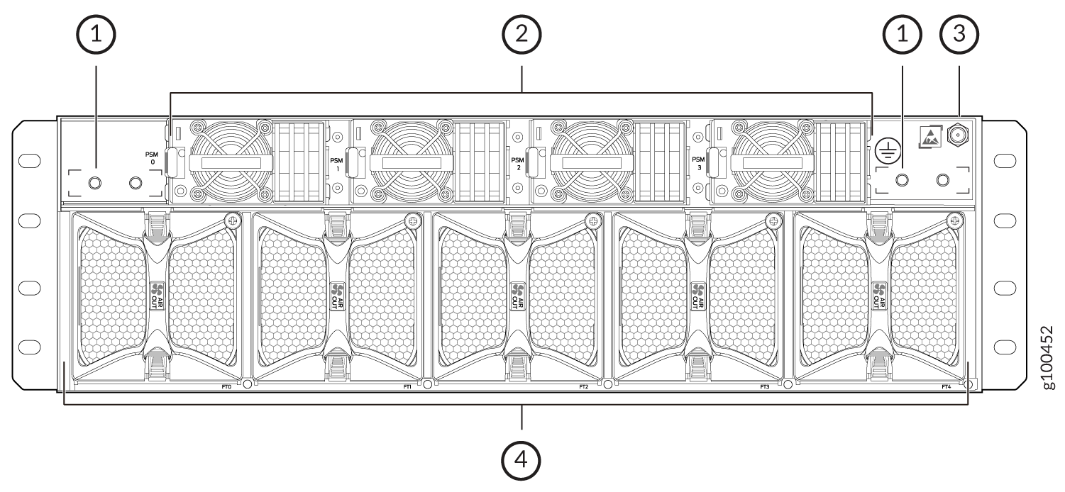
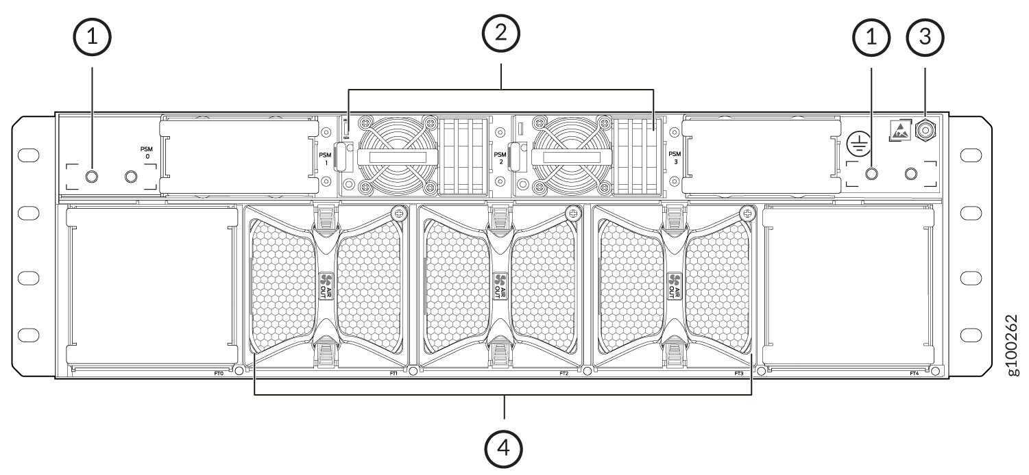
Figure 1 shows the location of the AC/HVDC power supplies on the PTX10003-160C FRU panel, and Figure 2 shows the location of the AC/HVDC power supplies on the PTX10003-80C FRU panel.
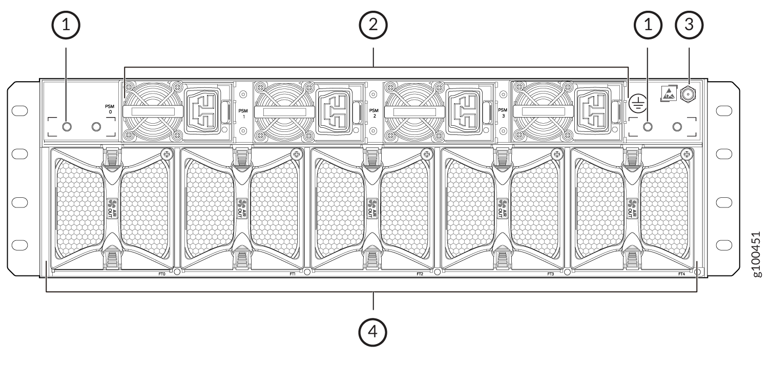
1 — Chassis grounding points (2) | 3 — ESD grounding point |
2 — AC/HVDC Power supplies (4) | 4 — Fan modules (5) |
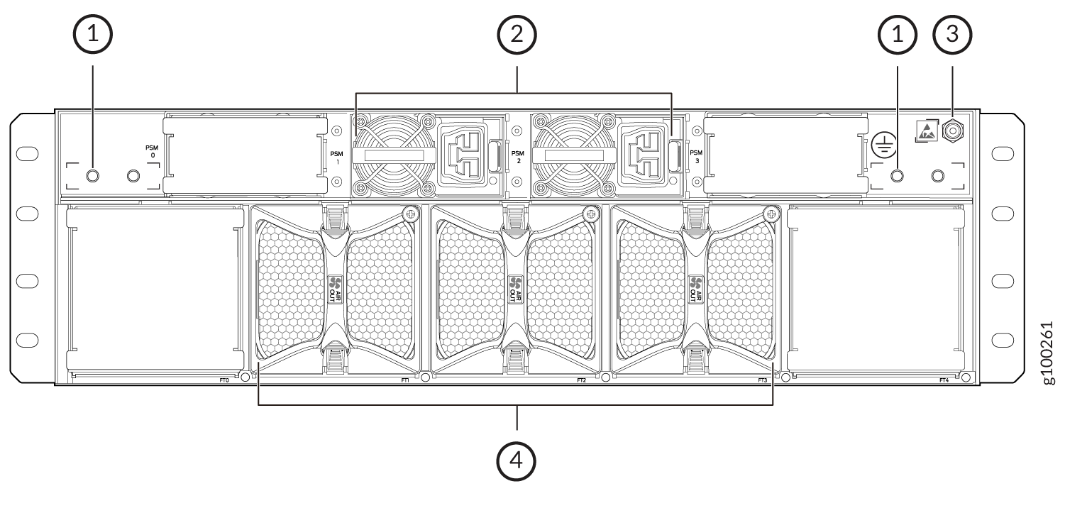
1 — Chassis grounding points (2) | 3 — ESD grounding point |
2 — AC/HVDC power supplies (2) | 4 — Fan modules (3) |
Figure 3 shows the AC/HVDC power supply module components.
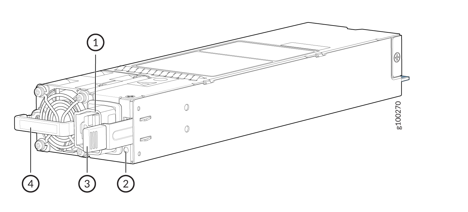
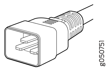
1 — Power plug connector | 3 — Ejector lever |
2 — Status LED | 4 — Orange handle |
To avoid electrical injury, carefully follow the instructions in Maintaining the PTX10003 Power Supplies.
- PTX10003 AC/HVDC Power Supply LED
- PTX10003 AC/HVDC Power Specifications
- PTX10003 AC Power Cord Specifications
PTX10003 AC/HVDC Power Supply LED
Each PTX10003 AC/HVDC power supply module has a status LED on the power supply module faceplate. Refer to Figure 4.
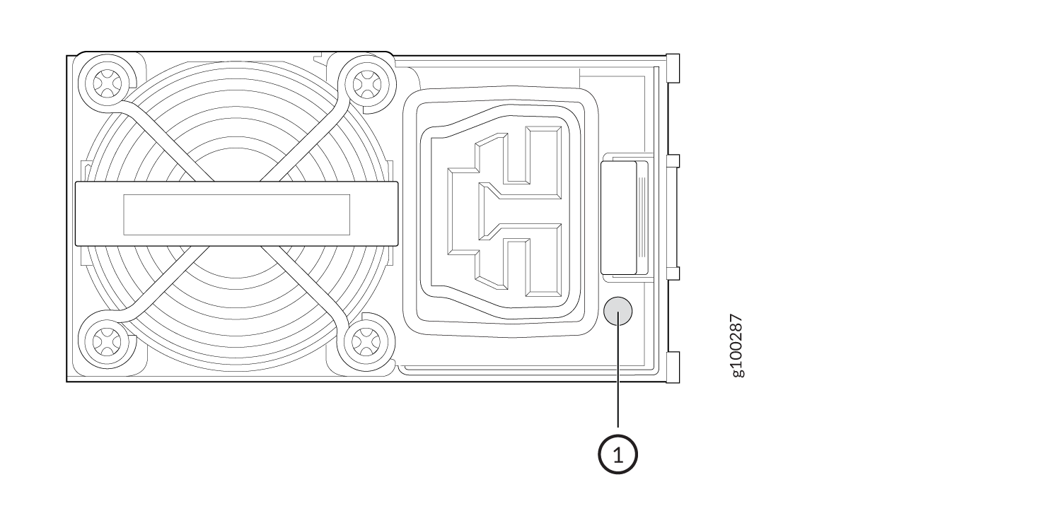
1 — Power supply LED |
The PTX10003 AC/HVDC power supply module uses an amber and green bi–color LED to indicate the operating state. Refer to Table 1.
State |
Green |
Amber |
|---|---|---|
The power supply module is on and operating properly |
On |
Off |
One or both power supplies do not have AC power |
Off |
Off |
The power supply module shut down due to a critical event. Possible causes: high temperature, high power, high current, fan failure |
Off |
On |
The power supply module is operating but there are warning events. Possible conditions: high temp (inlet temperature is greater than 53 degrees or a hot spot temperature is greater than 95 degrees), high power, high current, slow fan (less than 1200 rpm) |
Off |
Blinking amber |
There is no input power but the power supply module from another slot in the same system is on with 12 VSB active |
Blinking |
Off |
The AC power cord is unplugged |
Off |
On |
You can get additional information about the status of the power
supply modules using the show chassis power command and
the show chassis power detail command. Here’s some
examples of the CLI output:
PTX10003-160C Power with Four AC/HVDC Power Supplies
user@device> show chassis power
Chassis Power	Input(V)	Used(W)

Total Power 2052

PDU 0 2052
	PSM 0
		Input 1 226 489
		Capacity: 3000 W (maximum 3000 W)
	PSM 1
		Input 1 227 546
		Capacity: 3000 W (maximum 3000 W)
	PSM 2
		Input 1 226 435
		Capacity: 3000 W (maximum 3000 W)
	PSM 3
		Input 1 227 582
		Capacity: 3000 W (maximum 3000 W)


user@device> show chassis power detail
Chassis Power Input(V) Used(W)

Total Power 2044

PDU 0 2044
	PSM 0
		Input 1 226 489
		Capacity: 3000 W (maximum 3000 W)
	PSM 1
		Input 1 227 534
		Capacity: 3000 W (maximum 3000 W)
	PSM 2
		Input 1 226 432
		Capacity: 3000 W (maximum 3000 W)
	PSM 3
		Input 1 227 589
		Capacity: 3000 W (maximum 3000 W)

Item Used(W)
Routing Engine 0 147
CB 0 382
FPC 0 308
FPC 1 297
FPC 2 290
FPC 3 318
Fan Tray 0 17
Fan Tray 1 13
Fan Tray 2 17
Fan Tray 3 15
Fan Tray 4 12

System:
Zone 0:
Capacity: 12000 W (maximum 12000 W)
Allocated power: 4650 W (7350 W remaining)
Actual usage: 2047 W
Total system capacity: 12000 W (maximum 12000 W)
Total remaining power: 7350 W
PTX10003-80C with Two AC/HVDC Power Supplies
user@device> show chassis power
Chassis Power        Input(V)      Used(W)

Total Power                         1498

  PDU 0                             1498
    PSM 1
      Input 1           204          798
      Capacity:          3000 W (maximum 3000 W)
    PSM 2
      Input 1           206          700
      Capacity:          3000 W (maximum 3000 W)


user@device> show chassis power detail

Chassis Power        Input(V)      Used(W)

Total Power                         1497

  PDU 0                             1497
    PSM 1
      Input 1           204          802
      Capacity:          3000 W (maximum 3000 W)
    PSM 2
      Input 1           205          695
      Capacity:          3000 W (maximum 3000 W)

Item                 Used(W)
  Routing Engine 0       76
  CB 0                  266
  FPC 0                 435
  FPC 1                 443
  Fan Tray 1              8
  Fan Tray 2              7
  Fan Tray 3              8

System:
  Zone 0:
      Capacity:          6000 W (maximum 6000 W)
      Allocated power:   2807 W (3193 W remaining)
      Actual usage:      1495 W
  Total system capacity: 6000 W (maximum 6000 W)
  Total remaining power: 3193 W
PTX10003 AC/HVDC Power Specifications
The PTX10003 operates within the AC/HVDC input voltage range listed in Table 2.
Parameter |
Minimum |
Rated |
Maximum |
|---|---|---|---|
Input voltage (AC) |
180 VAC |
200–277 VAC |
305 VAC |
Input voltage (HVDC) |
190 VDC |
240–380 VDC |
400 VDC |
AC input line frequency |
47 Hz |
50–60 Hz |
63 Hz |
PTX10003 AC Power Cord Specifications
Detachable AC power cords are shipped with the AC power supplies. PTX10003 Default Power Cords Supplied lists the default power cord that is provided for each country. The plug end of the power cord fits into the power source outlet that is standard for your geographical location.
In North America, AC power cords must not exceed 14.75 feet (approximately 4.5 meters) in length, to comply with National Electrical Code (NEC) Sections 400-8 (NFPA 75, 5-2.2) and 210-52 and Canadian Electrical Code (CEC) Section 4-010(3). The cords that can be ordered for the PTX10003 are in compliance.
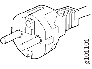
Table 3 lists the specifications of the AC power cord provided for each country or region.
Locale |
Cord Set Rating |
Plug Standards |
Spare Juniper Model Number |
Graphic |
|---|---|---|---|---|
Argentina |
16 A, 250 VAC |
IRAM 2073 Type RA/3 |
CBL-JNP-SG4-AR |
 |
Australia and New Zealand |
15 A, 250 VAC |
AS/NZS 4417 |
CBL-JNP-SG4-AU |
 |
Brazil |
16 A, 250 VAC |
NBR 14136 Type BR/3 |
CBL-JNP-SG4-BR |
 |
China |
16 A, 250 VAC |
GB2099 |
CBL-JNP-SG4-CH |
 |
|
China, Europe, and Japan |
16 A, 250 VAC |
C20 to Anderson 3-5958p4 |
CBL-JNP-SG4-C20-CH |

|
Europe (except Italy, Switzerland, and United Kingdom) |
20 A, 250 VAC |
CEE 7/7 STRAIGHT |
CBL-JNP-SG4-EU |
|
Great Britain |
13 A, 250 VAC, |
BS1363 |
CBL-JNP-SG4-UK |
 |
India |
16 A, 250 VAC |
SANS 164/1 |
CBL-JNP-SG4-SA |
 |
Israel |
16 A, RA, 250 VAC |
SI 32/1971 Type IL/3G |
CBL-JNP-SG4-IL |
 |
Italy |
16 A, 250 VAC |
CEI 23-16 |
CBL-JNP-SG4-IT |
 |
| Japan |
20 A, 250 VAC |
Nema L-20 |
CBL-JNP-SG4-JPL |
|
North America |
20 A, 250 VAC |
C20 to Anderson 3-5958p4 |
CBL-JNP-SG4-C20 |
 |
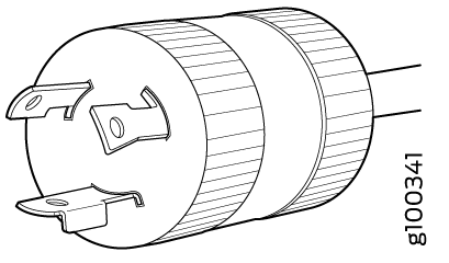
North America |
16 A, 250 VAC |
Locking NEMA L6-20P |
CBL-JNP-SG4-US-L |
|
North America |
16 A, 250 VAC |
NEMA 6-20P |
CBL-JNP-SG4-US |
 |
North America |
15 A, 277 V |
NEMA I7-20P |
CBL-JNP-SG4-HVAC |
 |
North America |
20 A, 250 V |
IEC 320P6W |
CG_CBL-APP-400-02 |
 |
South Africa |
16 A, 250 VAC |
SANS 164/1 |
CBL-JNP-SG4-SA |
|
Switzerland |
16 A, 250 VAC |
CEI 23-50 |
CBL-JNP-SG4-SZ |
|
|
Locale |
Spare Juniper Model Number |
Graphic |
|---|---|---|
|
Australia, Cook Islands, Fiji, Kiribati, Nauru, New Zealand, Papua New CBL-JNP-SG4-AU Guinea, Samoa, Tonga, and Vanuatu |
CBL-JNP-SG4-AU |
|
|
Brazil |
CBL-JNP-SG4-BR |
|
|
China |
CBL-JNP-SG4-CH |
|
|
Afghanistan, Albania, Algeria, Andorra, Angola, Argentina, Armenia, Austria, Azerbaijan, Bangladesh, Belarus, Belgium, Benin, Bhutan, Bolivia, Bosnia and Herzegovina, Bulgaria, Burundi, Burkina Faso, Cambodia, Cameroon, Cape Verde, Central African Republic, Chad, Cocos Islands, Comoros, Croatia, Czech Republic, Democratic Republic of the Congo, Denmark, Djibouti, Dominica, East Timor, Egypt, Equatorial Guinea, Eritrea, Estonia, Ethiopia, Faroe Islands, Finland, France, French Guiana, Gabon, Georgia, Germany, Ghana, Gibraltar, Greece, Greenland, Guinea, Guinea-Bissau, Hungary, Iceland, Indonesia, Iran, Iraq, Isle of Man, Ivory, Coast, Jordan, Kuwait, Kazakhstan, Latvia, Libya, Lithuania, Luxembourg, Macau, Macedonia, Madagascar, Mali, Martinique, Mauritania, Mauritius, Moldova, Monaco, Mongolia, Montenegro, Morocco, Mozambique, Myanmar, Namibia, New Caledonia, Netherlands, Nepal, Nigeria, Norway, Pakistan, Paraguay, Poland, Portugal, Qatar, Republic of the Congo, Romania, Russia, Rwanda, Saint Barthelemy, Saint Kitts and Nevis, Saint Vincent and the Grenadines, Senegal, Serbia, Serbia and Montenegro, Sierra Leone, Slovakia, Slovenia, Somalia, Spain, Sri Lanka, Sudan, Suriname, Sweden, Syria, Tajikistan, Tanzania, Togo, Tunisia, Turkey, Turkmenistan, Ukraine, Uruguay, Uzbekistan, Vietnam, and Yemen |
CBL-JNP-SG4-EU |
|
|
Israel |
CBL-JNP-SG4-IL |
|
|
Chile, Italy, and San Marino |
CBL-JNP-SG4-IT |
|
|
South Africa |
CBL-JNP-SG4-SA |
|
|
Maldives and United Kingdom |
CBL-JNP-SG4-UK |
|
|
American Samoa, Anguilla, Antigua and Barbuda, Aruba, Barbados, Bahamas, Belize, Bermuda, British Virgin Islands, Canada, Cayman Islands, Colombia, Costa Rica, Cuba, Ecuador, El Salvador, Guam, Guatemala, Guyana, Haiti, Honduras, Jamaica, Japan, Laos, Lebanon, Liberia, Mexico, Montserrat, Micronesia, Netherlands Antilles, Niger, Panama, Peru, Philippines, Puerto Rico, Saudi Arabia, Taiwan, Thailand, Trinidad and Tobago, U.S. Virgin Islands, and Venezuela |
CBL-JNP-SG4-US-L |
|
|
United States |
CBL-JNP-SG4-C20 |
|
Locale |
Cord Set Rating |
Spare Juniper Model Number |
|---|---|---|
HVDC power cord |
16 A, 400 VAC |
CBL-PWR2-BARE |
The insulation color for wires in the HVDC cables are color coded. Green is ground, black is line, and white is neutral. For HVDC, the black and white wires are not polarity-sensitive. The black wire can be positive (+) or neutral (–) and the white wire can be positive (+) or negative (–).
PTX10003 DC Power Supply Description
The PTX10003 DC power supplies are hot-removable and hot-insertable FRUs. Each 3000 W power supply module has a single DC input and provides 12 VDC output with a standby voltage of 12 VDC. The PTX10003 DC power supplies can operate with an input current of 80 A or 60 A.
Support for a 60 A power source was added in Junos OS Evolved Release 19.4. If you are using an earlier release, you’ll need to use an 80 A power source. Be sure you set the DIP switch to 80 A when installing the PTX10003 DC power supply module.
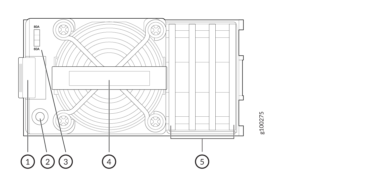
Figure 5 shows the location of the DC power supplies on the PTX10003-160C FRU panel, and Figure 6 shows the location of the DC power supplies on the PTX10003-80C FRU panel.
1 — Chassis grounding points (2) | 3 — ESD grounding point |
2 — DC power supplies (4) | 4 — Fan modules (5) |
1 — Chassis grounding points (2) | 3 — ESD grounding point |
2 — DC power supplies (2) | 4 — Fan modules (3) |
Figure 7 shows the DC power supply module components.
Do not mix AC/HVDC and DC power supplies in the same chassis.
1 — Ejector lever | 4 — Handle |
2 — Status LED | 5 — Terminal block cover |
3 — DC input current selector (DIP switch) |
To avoid electrical injury, carefully follow instructions in Maintaining the PTX10003 Power Supplies.
- PTX10003 DC Power Supply LED
- PTX10003 DC Input Current Selector (DIP Switch)
- PTX10003 Input DC Voltage Specification
- 60 A Input Feed Power Management
- PTX10003 DC Power Cables
- PTX10003 DC Power Lugs
- Viewing Power Statistics
PTX10003 DC Power Supply LED
Each PTX10003 DC power supply module has a status LED on the power supply module faceplate. Refer to Figure 8.
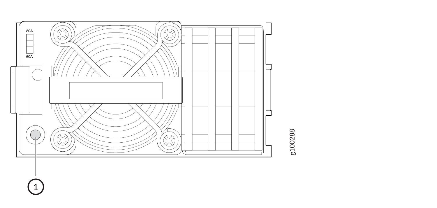
1 — Power supply status LED |
Use Table 6 to interpret the state of the power supply module status LED.
LED Color |
Power Supply State |
|---|---|
Solid green |
The power supply module is on and in the OK state. |
Off |
The power supplies do not have DC power |
Blinking green |
The power supply module is in cold redundant state |
Solid amber |
The DC power cord is unplugged but the second power supply module still has DC power |
Blinking amber |
The power supply module is operating but there are warning events. Possible causes: high temp, high power, high current, slow fan |
Solid amber |
The power supply module shut down due to a critical event. Possible causes: high temperature, high power, high current, slow fan |
Blinking green |
The power supply module is uploading firmware |
PTX10003 DC Input Current Selector (DIP Switch)
The PTX10003 DC power supply module can operate with an input current of 80 A or 60 A. You select the input rating by moving the DC input current selector (DIP switch) to the desired setting. If you select 60 A, the power supply module limits the output power so that the input current does not exceed 60 A under normal steady-state operation. If you select 80 A, the power supply module limits the output power so that the input current does not exceed 80 A.
For example:
If you select... |
Then... |
|---|---|
60 A |
The power supply module limits the output power to 2200 W when the input voltage is between 40V and 48V. It linearly increases the output power if the input voltage increases. The power supply module provides 2700 W output power when the input voltage is between 48V and 72V. |
80 A |
The power supply module provides 3000 W output power throughout the input voltage range from 40 VDC to 72 VDC. |
PTX10003 Input DC Voltage Specification
The PTX10003 DC power supply modules operate within the DC input voltage range listed in Table 7.
Support for a 60 A power source was added in Junos OS Evolved Release 19.4. If you are using an earlier release, you’ll need to use an 80 A power source. Be sure you set the DIP switch to 80 A when installing the PTX10003 DC power supply module.
Depending on the available input source, Juniper recommends that the 48-VDC facility DC source be equipped with a circuit breaker rated at a minimum of 60 A (48 VDC) or 80 A (48 VDC), or as required by local code.
Input Switch Setting |
Minimum Input DC Voltage |
Rated Input DC Voltage |
Maximum Input DC Voltage |
Maximum Input DC Current |
Maximum Output Power |
|---|---|---|---|---|---|
60 A |
40 VDC |
48 VDC to 60 VDC |
72 VDC |
60 ADC |
2700 W |
80 A |
40 VDC |
48 VDC to 60 VDC |
72 VDC |
90 ADC |
3000 W |
60 A Input Feed Power Management
The 60 A DC power supply module capacity changes when the input voltage is below or above the under voltage limit as follows:
When the 60 A DC power supply module input voltage is above the input under voltage warning limit, its capacity is 2700 W.
When the input voltage is below the input under voltage warning limit, the power supply module capacity is reduced to 2200 W.
When the input voltage is above the input under voltage warning limit, the software adjusts the system capacity and reallocates power to the FRUs based on the new system capacity. Table 8 shows system behavior in different scenarios with 60 A DC power supply modules.
Input voltage: < 40V |
Input voltage: > 40V and < 48V |
Input voltage: 48V to 72V |
|
|---|---|---|---|
60 A DC mode |
The power supply module is powered off and won’t turn on when the system is powering up. |
Alarms are raised but as long as there is sufficient power, the power supply module and system will remain online. If you need more power, power off the FPC first. |
Normal operation |
PTX10003-80C with two power supply modules |
The power supply modules are offline and the system is powered down. |
All FPCs are online but there’s no power supply module redundancy. |
Normal operation. |
PTX10003-80C with one power supply modules |
The power supply modules are offline and the system is powered down. |
Power off FPC1 and keep FPC0 online. There’s no power supply module redundancy. |
Normal operation, but there’s no power supply module redundancy. |
PTX10003-160C with four power supply modules |
The power supply modules are offline and the system is powered down. |
All FPCs are online but there’s no N + 2 power supply module redundancy. |
Normal operation. |
PTX10003-160C with three power supply modules |
The power supply modules are offline and the system is powered down. |
All FPCs are online but there’s no power supply module redundancy. |
Normal operation, but there’s no N + 2 power supply module redundancy. |
PTX10003-160C with two power supply modules |
The power supply modules are offline and the system is powered down. |
Power off FPC3 and keep the remaining three FPCs online. There’s no power supply module redundancy |
Normal operation, but there’s no power supply module redundancy. |
PTX10003-160C with one power supply module |
The power supply modules are offline and the system is powered down. |
Power off FPC1, FPC2, and FPC3, and keep FPC0 online. There’s No power supply module redundancy. |
Power off FPC1, FPC2,and FPC3, and keep FPC0 online. There’s no power supply module redundancy. |
The worst case scenario is when all power supply module inputs
are at the same voltage level. It’s possible that FPC1, FPC2,
or FPC3 of the four power supply modules are operating in a reduced
capacity and the rest of the power supply modules are operating at
a normal capacity. In all those scenarios, power management actions
can be different but deterministic based on the total system capacity
and total system power required. Use the show chassis power detail command to determine the behavior.
PTX10003 DC Power Cables
You must supply the DC power cables that meet the specifications required by the local code, laws, and standards. You must connect the power supply terminal marked (-48) to -48V or +48V RTN, and the terminal marked (RTN) to -48V RTN or +48V.
You must ensure that power connections maintain the proper polarity.
For field-wiring connections, use copper conductors only.
DC Power cables must not block access to PTX10003 components or drape where people could trip on them.
PTX10003 DC Power Lugs
The accessory box shipped with the PTX10003 includes the cable lugs that attach to the terminal studs of each power supply module. (The cable lug shown in Figure 9 is also used for grounding the chassis.) The cable lugs are dual hole and sized to fit 1/4-20 UNC terminal studs at 15.86-mm (0.625-in.) center line.
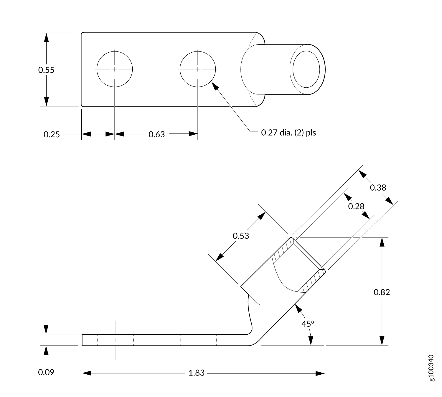
Before you begin to install the PTX10003, a licensed electrician must attach a cable lug to the power cables that you supply. A cable with an incorrectly attached lug can damage the PTX10003.
Viewing Power Statistics
You can get additional information about the status of the power
modules using the show chassis power command and show
chassis power detail command. Here’s some examples of
the CLI output:
PTX10003-160C with Four DC Power Supplies
user@device> show chassis power
Chassis Power        Input(V)      Used(W)

Total Power                          126
  PDU 0                              126
    PSM 0
      Input 1            51            2
      Capacity:          3000 W (maximum 3000 W)
    PSM 1
      Input 1            51           11
      Capacity:          3000 W (maximum 3000 W)
    PSM 2
      Input 1            51           60
      Capacity:          3000 W (maximum 3000 W)
    PSM 3
      Input 1            51           53
      Capacity:          3000 W (maximum 3000 W)


user@device> show chassis power detail

Chassis Power        Input(V)      Used(W)

Total Power                          176

  PDU 0                              176
    PSM 0
      Input 1            51            2
      Capacity:          3000 W (maximum 3000 W)
    PSM 1
      Input 1            51           53
      Capacity:          3000 W (maximum 3000 W)
    PSM 2
      Input 1            51           62
      Capacity:          3000 W (maximum 3000 W)
    PSM 3
      Input 1            51           59
      Capacity:          3000 W (maximum 3000 W)

Item                 Used(W)
  Routing Engine 0      101
  Fan Tray 0              7
  Fan Tray 1              7
  Fan Tray 2              8
  Fan Tray 3              9
  Fan Tray 4              5

System:
  Zone 0:
      Capacity:          12000 W (maximum 12000 W)
      Allocated power:   1607 W (10393 W remaining)
      Actual usage:      174 W
  Total system capacity: 12000 W (maximum 12000 W)
  Total remaining power: 10393 W
PTX10003-80C with two DC Power Supplies
user@device>show chassis power
Chassis Power        Input(V)      Used(W)

Total Power                         1558

  PDU 0                             1558
    PSM 1
      Input 1           203          777
      Capacity:          3000 W (maximum 3000 W)
    PSM 2
      Input 1           204          781
      Capacity:          3000 W (maximum 3000 W)

root@re0> show chassis power detail
Chassis Power        Input(V)      Used(W)

Total Power                         1561

  PDU 0                             1561
    PSM 1
      Input 1           203          804
      Capacity:          3000 W (maximum 3000 W)
    PSM 2
      Input 1           204          757
      Capacity:          3000 W (maximum 3000 W)

Item                 Used(W)
  Routing Engine 0       85
  CB 0                  274
  FPC 0                 465
  FPC 1                 467
  Fan Tray 1             12
  Fan Tray 2             12
  Fan Tray 3              9

System:
  Zone 0:
      Capacity:          6000 W (maximum 6000 W)
      Allocated power:   2750 W (3250 W remaining)
      Actual usage:      1563 W
  Total system capacity: 6000 W (maximum 6000 W)
  Total remaining power: 3250 W