PTX10003 Port Panel
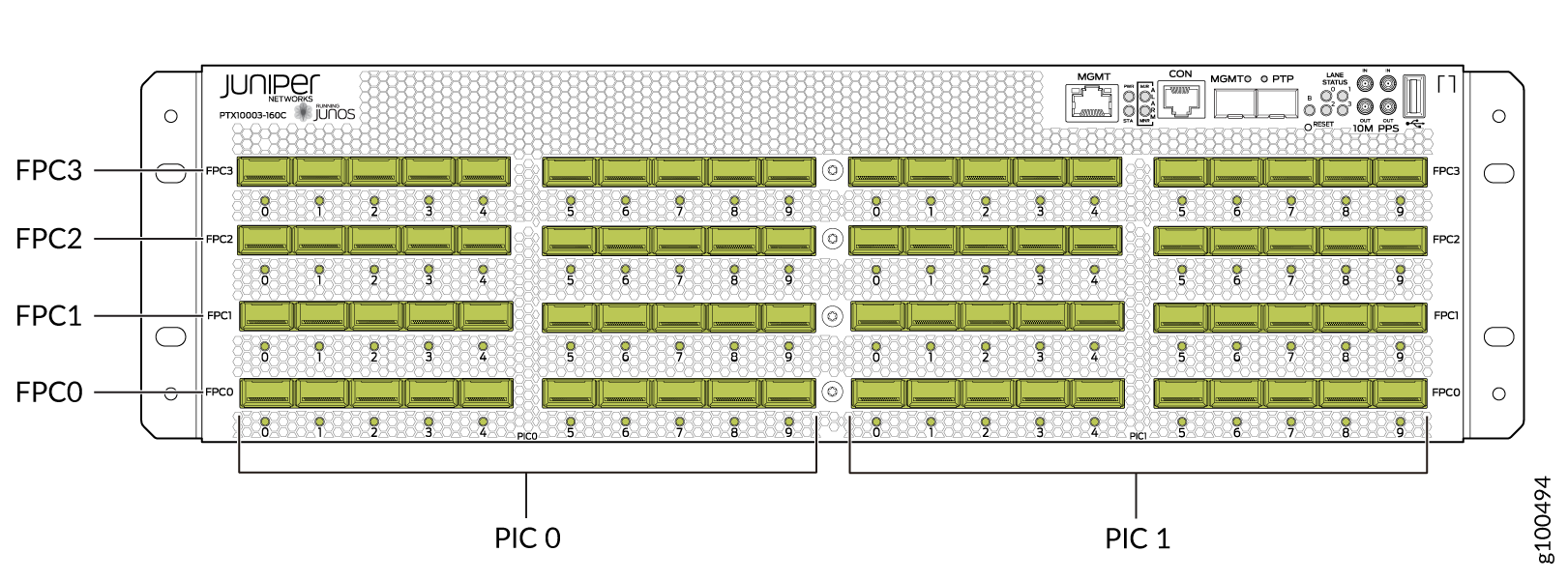
PTX10003-160C Port Panel
Operating in a fixed core router configuration, the PTX10003-160C features flexible interface configuration options with universal multi-rate double-density Quad Small Form-factor Pluggable (QSFP-DD) optics. The port panel has 80 optical interfaces which support data rates of 10 Gbps, 25 Gbps, 40 Gbps, 100 Gbps, and 400 Gbps. Each of the 16 Juniper Networks 1 Tbps ExpressPlus ASICs in the PTX10003-160C connect to a group of five QSFP-DD ports. You can configure different data rates for each port group as long as the total throughput for the group does not exceed 1 Tbps. For more details, see Understanding QSFP-DD Interfaces and Configurations.
Figure 1 illustrates the PTX10003-160C port panel.
1 — 80 optical interfaces with 80 port LEDs |
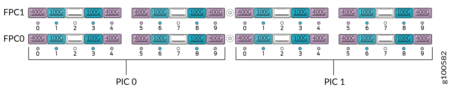
As illustrated in Figure 1, the interfaces for the PTX10003-160C are divided into logical FPCs, logical PICs, and physical optical ports as follows:
-
FPCs: The PTX10003-160C has four FPCs, numbered 0, 1, 2, and 3 from the bottom up in the chassis.
-
PICs: Each FPC has two logical PICs, numbered 0 and 1 from left to right.
-
Ports:: Each PIC controls 10 QSFP-DD optical interfaces, numbered 0 through 9 from left to right.
-
The 10 QSFP-DD optical interfaces are divided into two groups of five ports.
-
Each port group is controlled by two PFEs.
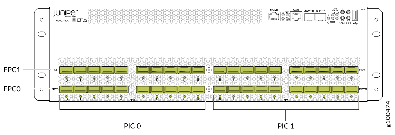
PTX10003-80C Port Panel
Operating in a fixed core router configuration, the PTX10003-80C features flexible interface configuration options with universal multi-rate double-density Quad Small Form-factor Pluggable (QSFP-DD) optics. The port panel has 40 optical interfaces which support data rates of 10 Gbps, 25 Gbps, 40 Gbps, 100 Gbps, and 400 Gbps. Each of the eight Juniper Networks 1 Tbps ExpressPlus ASICs in the PTX10003-80C connect to a group of five QSFP-DD ports. You can configure different data rates for each port group as long as the total throughput for the group does not exceed 1 Tbps. See Understanding QSFP-DD Interfaces and Configurations for more details.
Figure 2 illustrates the PTX10003-80C port panel.
1 — 40 optical interfaces with 40 port LEDs |
As illustrated in Figure 2, the interfaces for the PTX10003-80C are divided into logical FPCs, logical PICs, and physical optical ports as follows:
-
FPCs: The PTX10003-80C has two FPCs, numbered 0 and 1 from the bottom up in the chassis.
-
PICs: Each FPC has two logical PICs, numbered 0 and 1 from left to right.
-
Ports: Each PIC controls 10 QSFP-DD optical interfaces, numbered 0 through 9 from left to right.
-
The 10 QSFP-DD optical interfaces are divided into two groups of five ports.
-
Each port group is controlled by two Packet Forwarding Engines (PFE).
Understanding QSFP-DD Interfaces and Configurations
Each Juniper Networks 1 Tbps ExpressPlus ASIC contains two logically independent PFEs which can provide 500 Gbps throughput. Each QSFP-DD port group is controlled by two PFEs with the middle QSFP-DD interface (port 2 and port 7) being shared by the PFEs.
Any port can be used as a 100-Gigabit Ethernet interface, 40-Gigabit Ethernet interface, or 10-Gigabit Ethernet interface. You choose the speed by plugging in the appropriate optical transceiver. You can also channelize the 100 Gbps ports to create multiple independent 25 Gbps interfaces. You can channelize the 40 Gbps ports to create multiple independent 10 Gbps ports. See Channelization Configuration on PTX10003 for more details.
Given the design of the Juniper Networks ExpressPlus ASIC and chassis level thermal considerations, there are certain limitations for some QSFP-DD interfaces and configurations. Each QSFP-DD port group can be configured to achieve the maximum 1 Tbps throughput with the following limitations:
-
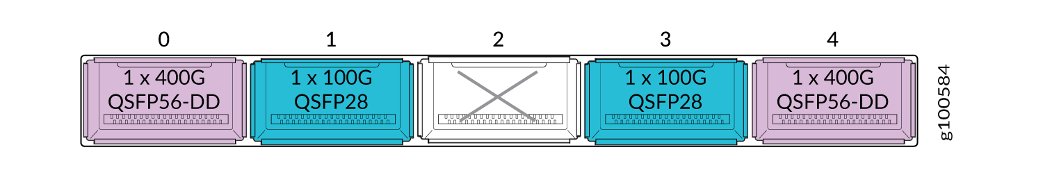
Only the interfaces at the outer edge of each QSFP-DD group can be configured for 1x400 Gbps (using QSFP56-DD optics).
-
The QSFP-DD port in the middle (port 2 and port 7) is shared across two PFEs. These ports can support 2x100 Gbps (QSFP28-DD).
-
The highest QSFP-DD data rate that can be used across all QSFP-DD groups is 200 Gbps (2x100 Gbps). This provides 16 Tbps throughput for the PTX10003-160C, and 8 Tbps throughput for the PTX10003-80C.
-
Aside from running all interfaces with 2x100 Gbps optics, there are other ways to attain the maximum system throughput. The 400 Gbps optics can be used in combination with 100 Gbps optics and 200 Gbps optics as shown in the following examples.
Allowable QSFP-DD Interface Configurations for the PTX10003-160C
Assuming the limitations described previously, Table 1 lists the allowable interface configurations for the PTX10003-160C.
|
Number of Ports |
QSFP Transceiver |
Data Rate |
Maximum Number of Interfaces |
|---|---|---|---|
|
80 |
QSFP+ |
4x10 Gbps |
320 10 Gbps |
|
1x40 Gbps |
80 40 Gbps |
||
|
80 |
QSFP28 |
1x100 Gbps |
80 100 Gbps |
|
4x25 Gbps |
320 25 Gbps |
||
|
80 |
QSFP28-DD |
2x100 Gbps |
160 100 Gbps |
|
8x25Gbps |
640 25 Gbps |
||
|
32 |
QSFP56-DD |
1x400 Gbps |
32 400 Gbps |
|
4x100 Gbps |
128 100 Gbps |
Allowable QSFP-DD Interface Configurations for the PTX10003-80C
Assuming the limitations described previously, Table 2 lists the allowable interface configurations for the PTX10003-80C.
|
Number of Ports |
QSFP Transceiver |
Data Rate |
Maximum Number of Interfaces |
|---|---|---|---|
|
40 |
QSFP+ |
4x10 Gbps |
160 10 Gbps |
|
1x40 Gbps |
40 40 Gbps |
||
|
40 |
QSFP28 |
1x100 Gbps |
40 100 Gbps |
|
4x25 Gbps |
160 25 Gbps |
||
|
40 |
QSFP28-DD |
2x100 Gbps |
80 100 Gbps |
|
8x25 Gbps |
320 25 Gbps |
||
|
16 |
QSFP56-DD |
1x400 Gbps |
16 400 Gbps |
|
4x100 Gbps |
64 100 Gbps |
Examples of PTX10003 QSFP-DD Configurations
By default, all PTX10003 QSFP-DD interfaces are configured for a data rate of 2x100 Gbps. You can change the port configuration to achieve different throughput using the following Junos OS Evolved command:
set chassis fpc slot-number pic
                        pic-number port port-number
                    number-of-subports [1 | 2 | 4  |8] speed [10G | 25G
                        | 40G | 100G | 400G]
command.
For example, to configure the second port in the first port group as a 4x10 Gbps
interface, use the set chassis fpc 0 pic 0 port 1 number-of-subports 4 speed
10g command. After you commit this configuration, the second port in
PIC 0 will operate at 4x10 Gbps.
When a port speed and sub-port-number are configured, the configured values
override the default port speed for the transceiver. If you try to configure a
port speed that is not supported by the transceiver, the port will be disabled.
If there isn’t a port speed configured on a valid optical port, the PTX10003
uses a default port speed of 2x100 Gbps. Also, if
number-of-subports is not configured, a 1x 40G |
100G |400G] data rate is assumed. You cannot configure a 1x10G
sub-port by using the CLI.
- Example: Using Network Ports as 10 Gbps or 40 Gbps Ethernet Interfaces
- Example: Using Network Ports as 100 Gbps Ethernet Interfaces
- Example: Using Network Ports as 1x400 Gbps Ethernet Interfaces
- Example: Using Network Ports as 4x100 Gbps Ethernet Interfaces
Example: Using Network Ports as 10 Gbps or 40 Gbps Ethernet Interfaces
With QSFP+ transceivers, you can configure 10 Gbps or 40 Gbps interfaces on any port. To attain the maximum 1 Tbps throughput for a port group, you can configure the 10 Gbps and 40 Gbps ports with combinations of 1x100 Gbps, 2x100 Gbps, and 400 Gbps, data rates. Refer to Table 3.
Starting in Junos OS Evolved Release 19.3R1, you can use the Mellanox 10-Gbps
pluggable adapter (model number: MAM1Q00A-QSA) to convert quad-lane-based
ports to a single-lane-based SFP+ port. The QSA adapter has the QSFP+ form
factor with a receptacle for the SFP+ module. Use the QSA adapter and the
set chassis fpc slot-number pic
                                pic-number port port-number
                            number-of-subports 4 speed 10G
command to convert a 40-Gbps
port to a 10-Gbps port. You can plug a 10-Gbps SFP+ transceiver into the QSA
adapter, which is then inserted into the QSFP or QSFP+ port of the
PTX10003-80C or PTX10003-160C router.
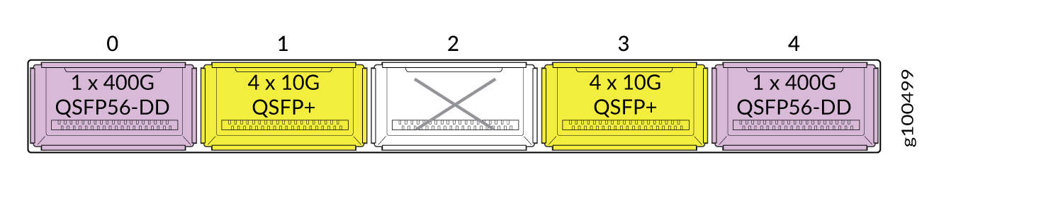
Only the ports at the outer edge of each group can be configured for 1x400 Gbps (using QSFP56-DD transceivers).
|
Data Rate |
QSFP Transceiver |
Allowable Port Numbers |
Maximum Number of Ports (PTX10003-160C) |
Maximum Number of Ports (PTX10003-80C) |
|---|---|---|---|---|
|
4x10 Gbps |
QSFP+ |
0-9 |
320 |
160 |
|
1x40 Gbps |
QSFP+ |
0-9 |
80 |
40 |
Example: Using Network Ports as 100 Gbps Ethernet Interfaces
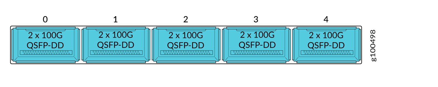
With QSFP28 and QSFP28-DD transceivers, you can configure a 2x100 Gbps data rate on any port. This is the default port configuration. To attain the maximum 1 Tbps throughput for a port group using 100 Gbps interfaces, you can configure combinations of 1x100 Gbps, 2x100 Gbps, and 4x100 Gbps data rates. Refer to Table 4.
|
Data Rate |
QSFP Transceiver |
Allowable Port Numbers |
Maximum Number of Ports (PTX10003-160C) |
Maximum Number of Ports (PTX10003-80C) |
|---|---|---|---|---|
|
1x100 Gbps |
QSFP28 |
0-9 |
80 |
40 |
|
2x100 Gbps |
QSFP28-DD |
0-9 |
160 |
80 |
|
4x100 Gbps |
QSFP56-DD |
0, 4, 5, 9 |
128 |
64 |
Example: Using Network Ports as 1x400 Gbps Ethernet Interfaces
With QSFP56-DD transceivers, you can configure a data rate of 1x400 Gbps on the two outer ports in a port group. To attain the maximum 1 Tbps throughput, you can configure combinations of two ports of 1x400 Gbps and two ports of 1x100 Gbps data rates in a port group with the following limitations:
-
Only the ports at the outer edge of each group can be configured for 1x400 Gbps (using QSFP56-DD transceivers).
-
When ports 0, 4, 5, 9 are configured as 1x400 Gbps, the center ports 2 and 7 must be blank. You must configure the blank ports by using the
set chassis fpc fpc-slot-number pic
                                    pic-slot-number port
                                    port-number unused
command.
|
Data Rate |
QSFP Transceiver |
Allowable Port Numbers |
Maximum Number of Ports (PTX10003-160C) |
Maximum Number of Ports (PTX10003-80C) |
|---|---|---|---|---|
|
1x400 Gbps |
QSFP56-DD |
0, 4, 5, 9 |
32 |
16 |
|
4x100 Gbps |
QSFP56-DD |
0, 4, 5, 9 |
128 |
64 |
|
2x100 Gbps |
QSFP28-DD |
0-9 |
160 |
80 |
Starting in Junos OS Evolved Release 19.3R1, we support 400 Gbps data rates.
Example: Using Network Ports as 4x100 Gbps Ethernet Interfaces
With QSFP56-DD transceivers, you can configure a data rate of 4x100 Gbps on the two outer ports in a port group. You can configure combinations of two ports of 4x100 Gbps with the following limitations:
- You can configure only the ports at the outer edge of each group to operate at 4x100 Gbps speeds (by using QSFP56-DD transceivers).
- When you configure port 0 to operate at 4x100 Gbps speeds, you cannot use port 1.
- When you configure port 4 to operate at 4x100 Gbps speeds, you cannot use port 3.
You must configure the ports not in use by using the set chassis fpc
fpc-slot-number pic
pic-slot-number port port-number
unused command.
PTX10003 Port LEDs
Each PTX10003 port uses a single bi-colored LED to indicate link status and activity. See Table 6 for how to interpret the port LEDs.
After you insert an optical transceiver, the LINK UP LED flashes red and green during the first 60 seconds. This means the link is unstable. It may take up to 60 seconds for the LED to stop flashing.
|
Color |
State |
Description |
|---|---|---|
|
— |
Off |
The transceiver is not present or loopback configuration is present. |
|
Green |
On steadily |
A link is established and all channels are up. |
|
Amber |
On steadily |
One or more channels are up. However, at least one channel has activity, but not all connections are active. |
|
Red |
On steadily |
All channels are down. |
Channelizing Interfaces on PTX10003 Routers with Junos OS Evolved
PTX10003 Packet Transport Routers feature flexible interface configuration options with universal multi-rate double-density Quad Small Form-factor Pluggable (QSFP-DD) optics. The PTX10003-80C port panel has 40 physical ports and the PTX10003-160C port panel has 80 physical ports. The physical ports are in groups of five QSFP-DD ports. You can configure different data rates for each port group as long as the total throughput for the group does not exceed 1 Tbps. Any port can be used as a 100-Gigabit Ethernet interface, 40-Gigabit Ethernet interface, or 10-Gigabit Ethernet interface. You choose the speed by plugging in the appropriate transceiver.
The QSFP-DD port in the middle in each port group (port 2 and port 7) is shared across two PFEs. These ports can support 2x100 Gbps. To configure a 200 Gbps data rate for those ports, you’ll need to configure them as 2x100 Gbps. For more details, see Understanding QSFP-DD Interfaces and Configurations.
You can channelize the Gigabit Ethernet interfaces on PTX10003 routers to create multiple independent Gigabit Ethernet interfaces and then use breakout cables to connect the channelized ports to other servers, storage devices, and routers. Here’s the allowable channelization configurations for the optical transceivers supported by the PTX10003:
|
QSFP Transceiver |
Native Port Speeds |
Channelization Options |
|---|---|---|
|
QSFP28-DD |
2x100 Gbps |
8x25 Gbps |
|
QSFP28 |
1x100 Gbps |
4x25 Gbps |
|
QSFP+ |
1x40 Gbps 4x10 Gbps |
4x10 Gbps |
By default, all PTX10003 QSFP-DD interfaces are configured for a data rate of 2x100 Gbps. The interface names appear in the et-fpc/pic/port:channel format.
The port speed can be configured at the PIC-level. To view the
port speed capability of a logical PIC, issue the show chassis
pic fpc-slot slot-number pic-slot slot-number
command.
For details on how to channelize a port, see PTX10003 Router Port Speed Overview.