Unpack and Mount the PTX10002-36QDD
Unpack the Router
The PTX10002-36QDD router chassis is a rigid sheet-metal structure that houses the hardware components. We ship the router in a carton that is secured to a wooden pallet base.
The routers are maximally protected inside the shipping carton. Do not unpack the routers until you are ready to mount the router.
Before you start unpacking the router, ensure that you have a cutter or knife to cut the straps that secure the carton to the wooden pallet base and the tapes on the carton.
To unpack the router:
- Move the carton along with the wooden pallet base to a staging area as close to the installation site as possible. While the chassis is strapped to the pallet, you can use a forklift or pallet jack to move the carton. Ensure that there is enough space to remove the system components.
- Position the carton such that the arrows on the carton are pointing up. If the arrows are not pointing up, you must return the router to the contract manufacturer.
- Use the cutter or knife to cut the straps that secure the shipping box to the wooden pallet base and the tapes on the carton.
- Open the top flaps on the carton.
- Pull out the corrugated support material below the carton flaps.
- Pull out the corrugated packing material holding the router in place.
- Remove the accessory box and place it on a on a flat, stable surface.
- Lift the carton off.
- Lift the chassis from the wooden pallet base manually and place it on a on a flat, stable surface.
- Verify the parts received against the inventory on the label attached to the carton (see Table 1). If any part on the packing list is missing, contact your customer service representative or contact Juniper customer care from within the U.S. or Canada by telephone at 1-888-314-5822. For international-dial or direct-dial options in countries without toll-free numbers, see https://www.juniper.net/support/requesting-support.html.
- Save the carton, accessory box, corrugated packing materials, and wooden pallet base in case you need to move or ship the router later.
| Component | Quantity |
|---|---|
|
Router |
1 |
|
Power supplies |
2 preinstalled |
|
Fan modules |
3 preinstalled |
|
(If you purchased a model with an AC/HVAC/HVDC power supply) Power cord appropriate for your geographical location |
1 |
|
Four-post mounting kit |
1 |
|
Documentation Roadmap |
1 |
|
Juniper Networks Product Warranty |
1 |
|
End-User License Agreement |
1 |
Update Base Installation Data
Update the installation base data if any addition or change to the installation base occurs or if the installation base is moved. Juniper Networks is not responsible for not meeting the hardware replacement SLA for products that do not have accurate installation base data.
Update your installation base at https://supportportal.juniper.net/s/CreateCase .
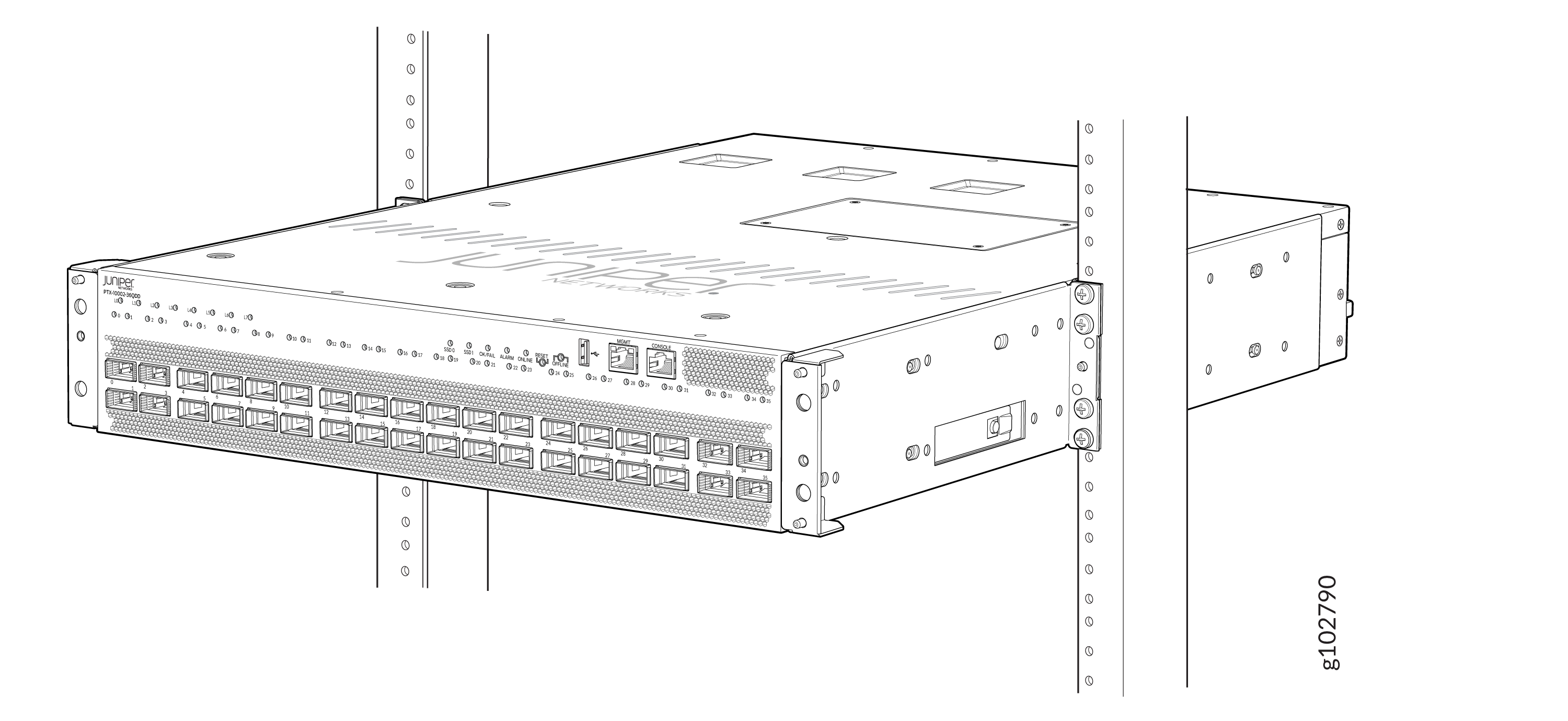
Mount the PTX10002-36QDD on a Square Hole Four-Post Rack
You can mount the router on:
-
Four posts of a 19-in. four-post rack or cabinet by using the four-post mounting kit (part number: JNP10002-4P-TL-RMK)—provided
-
Two posts of a 19-in. two-post rack or cabinet by using the two-post mounting kit (part number: JNP10002-2P-TL-RMK)—separately orderable
The remainder of this topic uses rack to mean rack or cabinet.
Before you mount the router on a square hole four-post rack:
-
Verify that the site meets the requirements described in Site Preparation Checklist for PTX10002-36QDD Routers.
-
Place the rack in its permanent location, allowing adequate clearance for airflow and maintenance, and secure the rack to the building structure.
-
Read Safety Information, with particular attention to Chassis and Component Lifting Guidelines.
-
Ensure that you have taken the necessary precautions to prevent electrostatic discharge (ESD) damage (see Prevention of Electrostatic Discharge Damage).
-
Unpack the router from the shipping carton (see Unpack the Router).
Ensure that you have the following parts and tools available:
-
A number 2 Phillips (+) screwdriver—not provided
-
An ESD grounding strap—not provided
-
The four-post mounting kit provided with the router that includes the following:
-
Front mounting rails—2
-
Rear mounting rails—2
-
Mounting brackets—2
-
Have one person to support the weight of the router while another person secures the router to the rack posts.
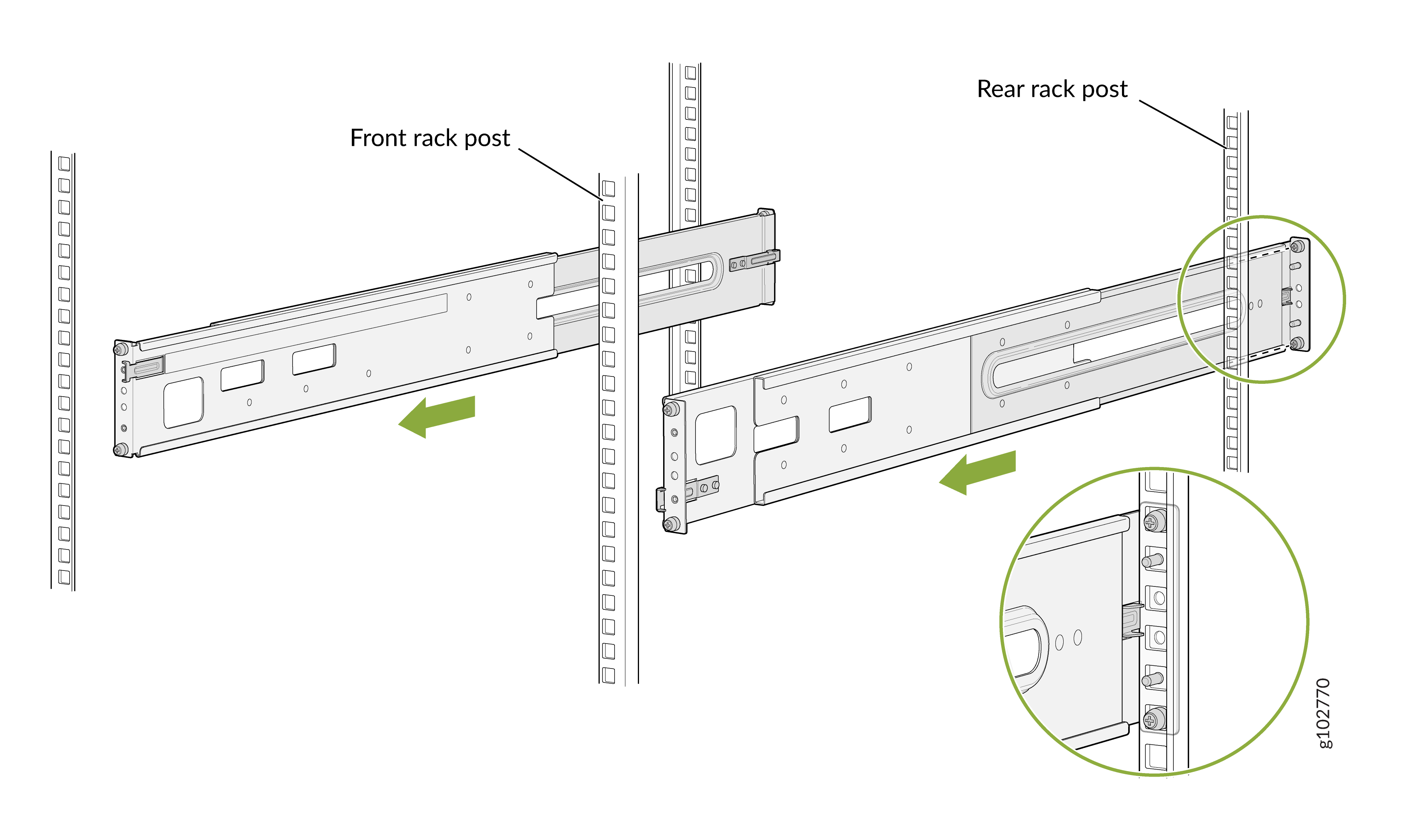
To mount the router on a square hole four-post rack:
-
Assemble both the right and left mounting rails. Align the rear mounting
rails with the guides on the front mounting rails and gently slide the rear
mounting rails into the front mounting
rails.

-
Attach the rear mounting rails to the rack posts—tighten the thumb screws
by using the
screwdriver.
-
Attach the front mounting rails to the rack posts—tighten the captive thumb
screws by using the
screwdriver.
-
Ensure that the mounting rails are level by verifying that all screws on
one side of the rack align with the screws on the other
side.
-
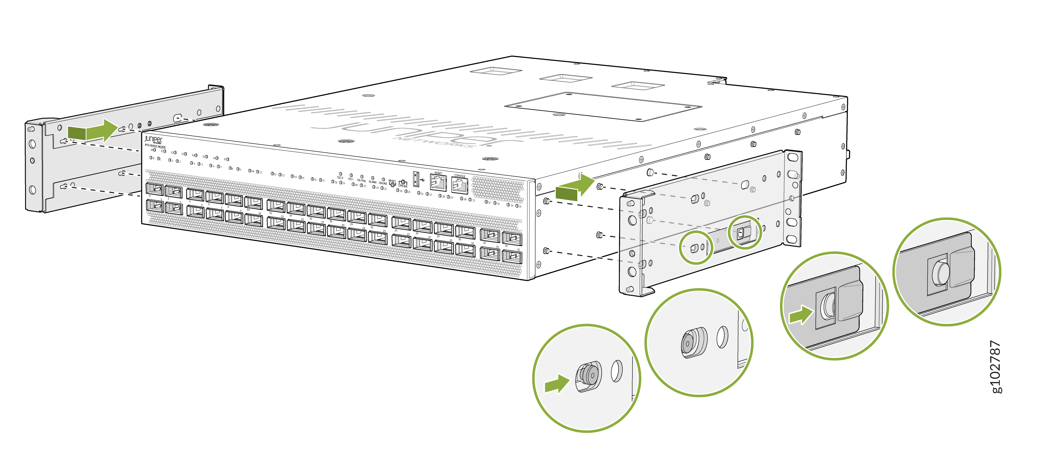
Attach the mounting brackets to the router
chassis.
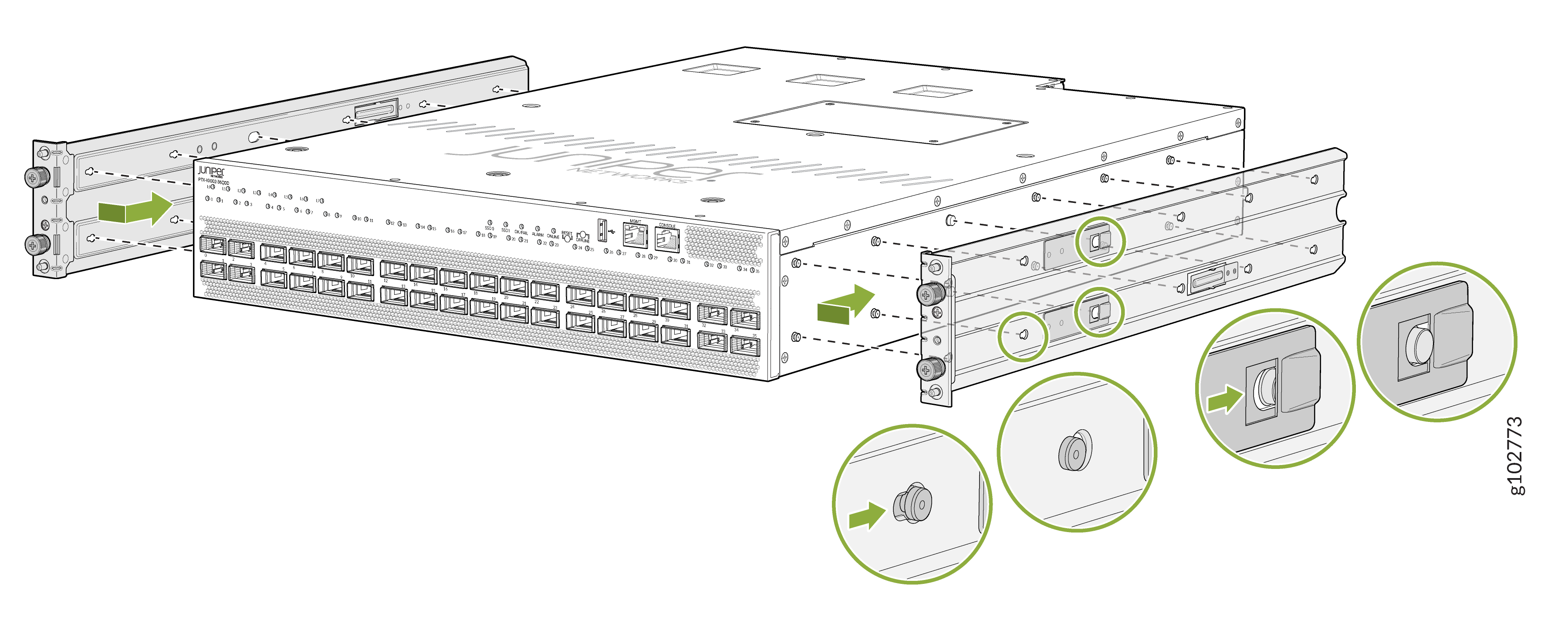
-
Align the mounting brackets with the guides on the mounting rails and
gently slide the chassis on to the mounting rails until the chassis locks in
place.
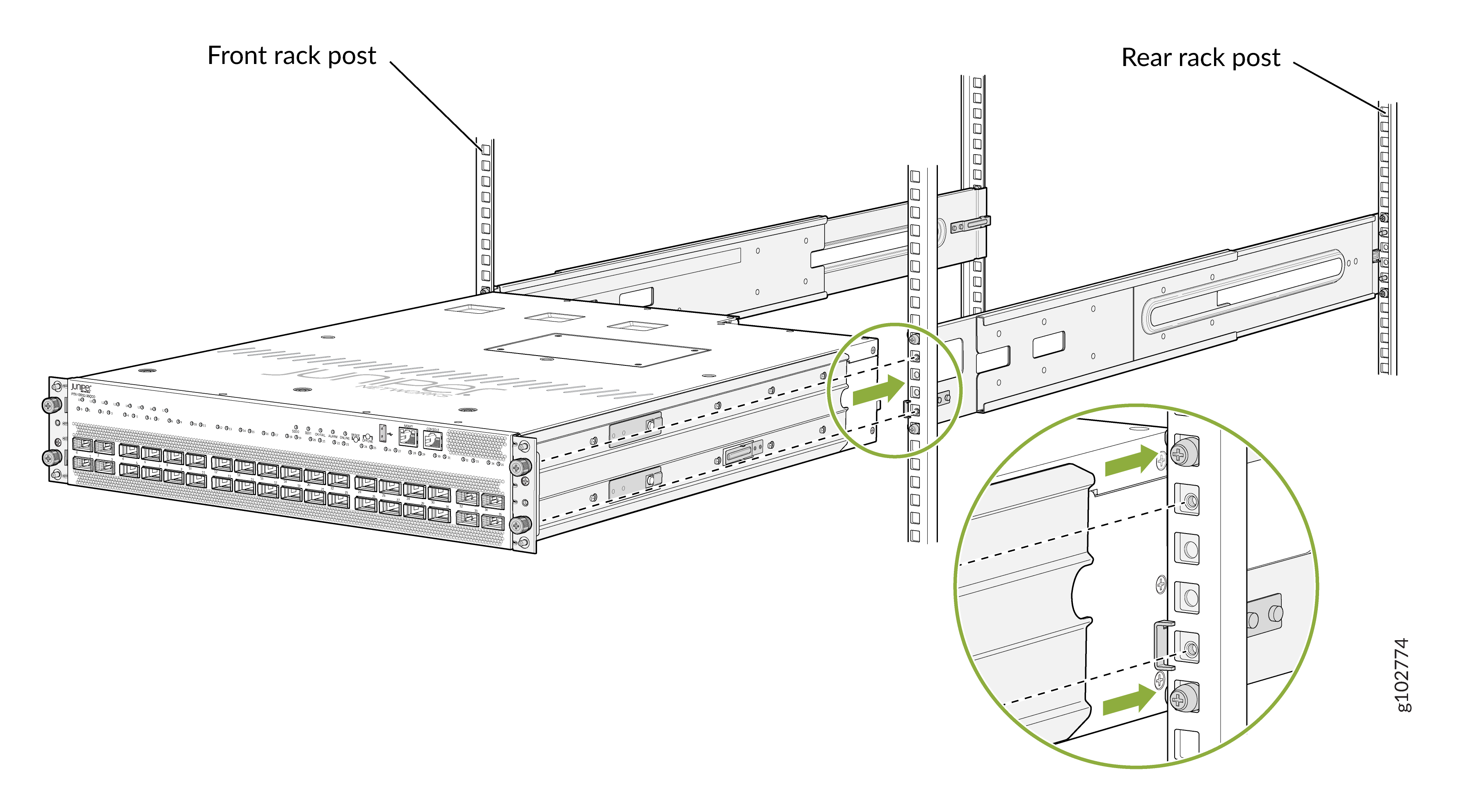
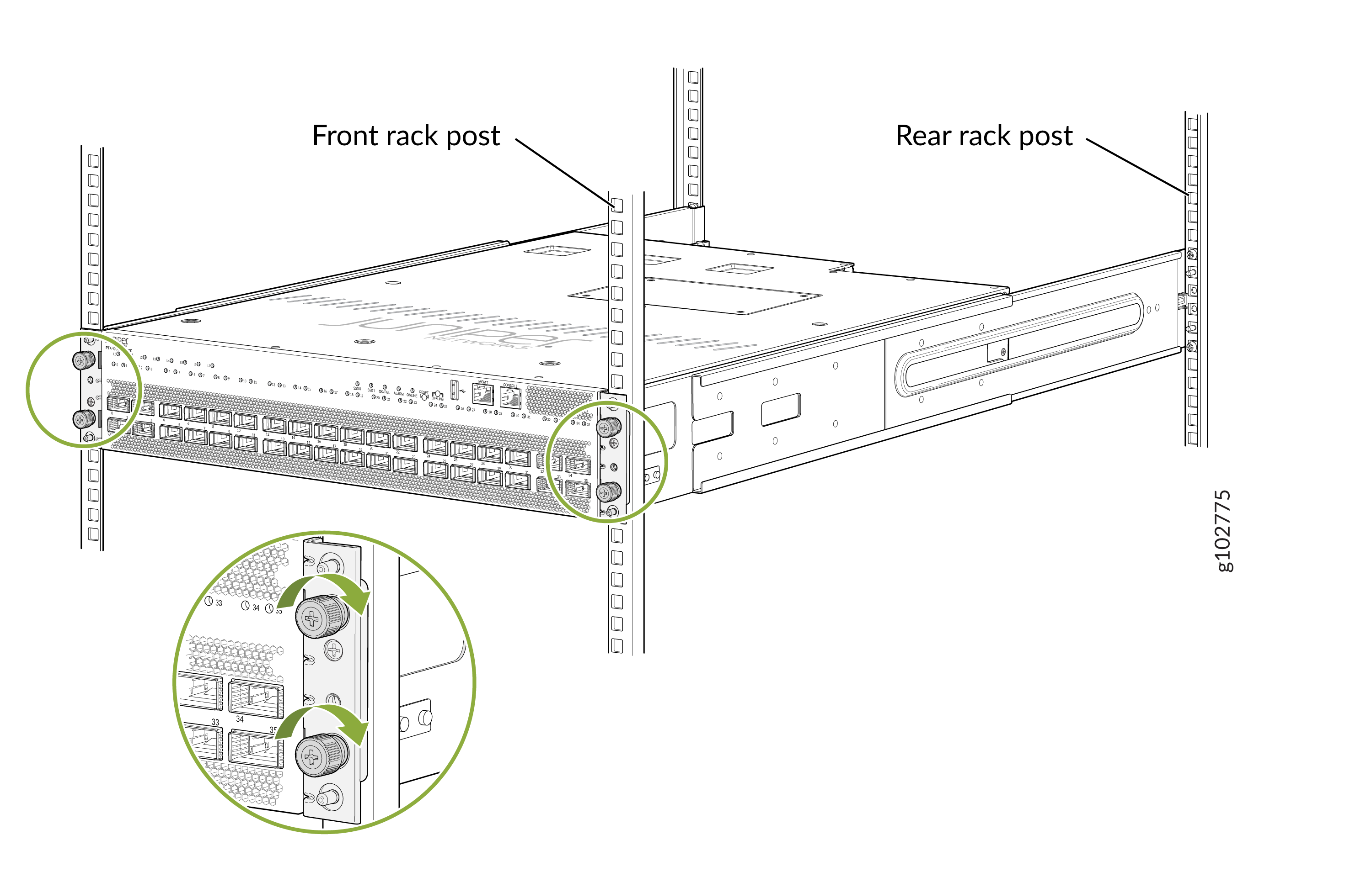
-
Secure the router to the rack—tighten the thumb screws by using the
screwdriver.
Mount the PTX10002-36QDD on a Threaded Hole Four-Post Rack
You can mount the router on:
-
Four posts of a 19-in. four-post rack or cabinet by using the four-post mounting kit (part number: JNP10002-4P-TL-RMK)—provided
-
Two posts of a 19-in. two-post rack or cabinet by using the two-post mounting kit (part number: JNP10002-2P-TL-RMK)—separately orderable
The remainder of this topic uses rack to mean rack or cabinet.
Before you mount the router on a threaded hole four-post rack:
-
Verify that the site meets the requirements described in Site Preparation Checklist for PTX10002-36QDD Routers.
-
Place the rack in its permanent location, allowing adequate clearance for airflow and maintenance, and secure the rack to the building structure.
-
Read Safety Information, with particular attention to Chassis and Component Lifting Guidelines.
-
Ensure that you have taken the necessary precautions to prevent electrostatic discharge (ESD) damage (see Prevention of Electrostatic Discharge Damage).
-
Unpack the router from the shipping carton (see Unpack the Router).
Ensure that you have the following parts and tools available:
-
A number 2 Phillips (+) screwdriver—not provided
-
An ESD grounding strap—not provided
-
An antistatic bag—not provided
-
The four-post mounting kit provided with the router that includes the following:
-
Front mounting rails—2
-
Rear mounting rails—2
-
Mounting brackets—2
-
Have one person to support the weight of the router while another person secures the router to the rack posts.
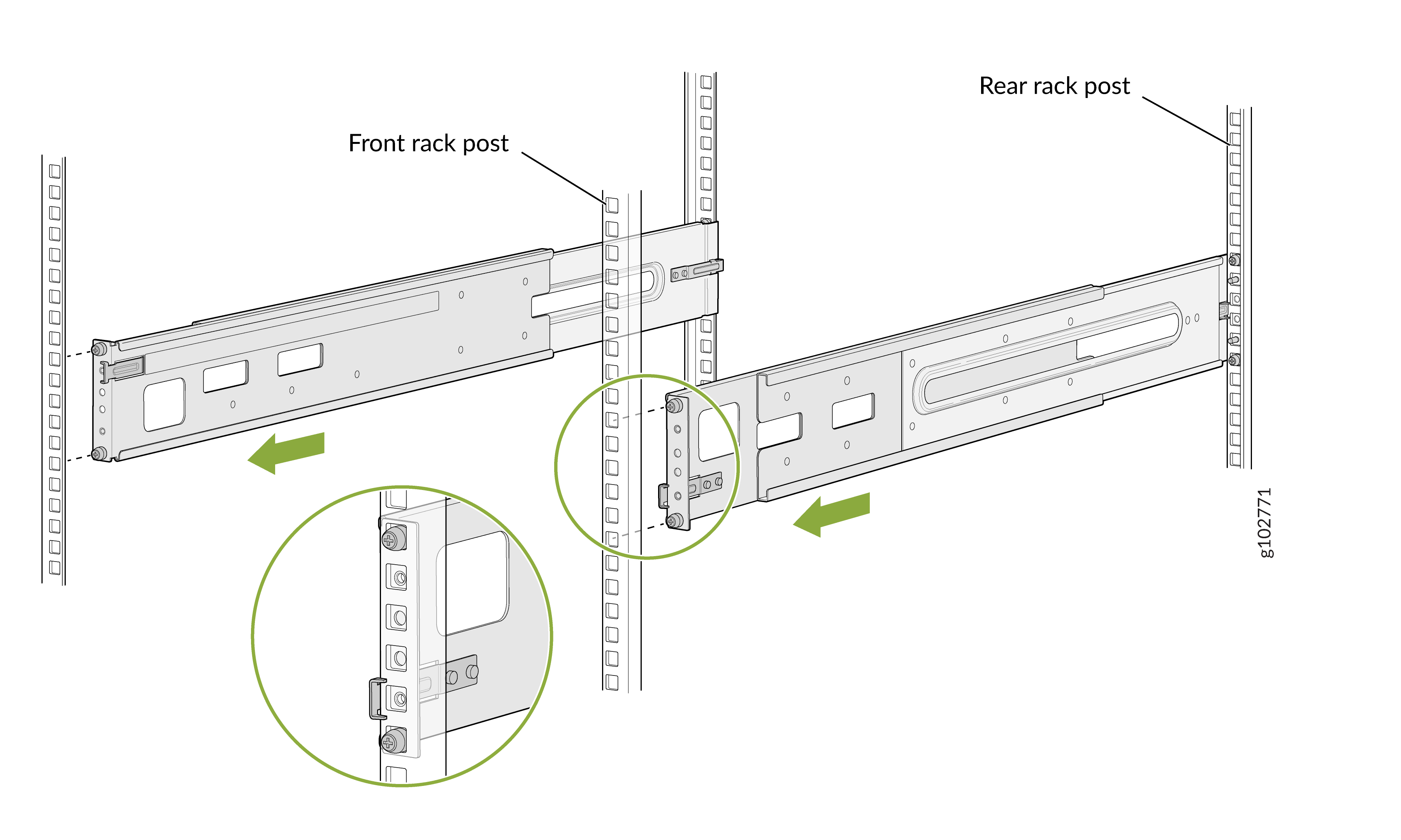
To mount the router on a threaded hole four-post rack:
-
Remove the guide blocks from the mounting rails by using the screwdriver.
Keep them in an antistatic bag. See Figure 1 and Figure 2.
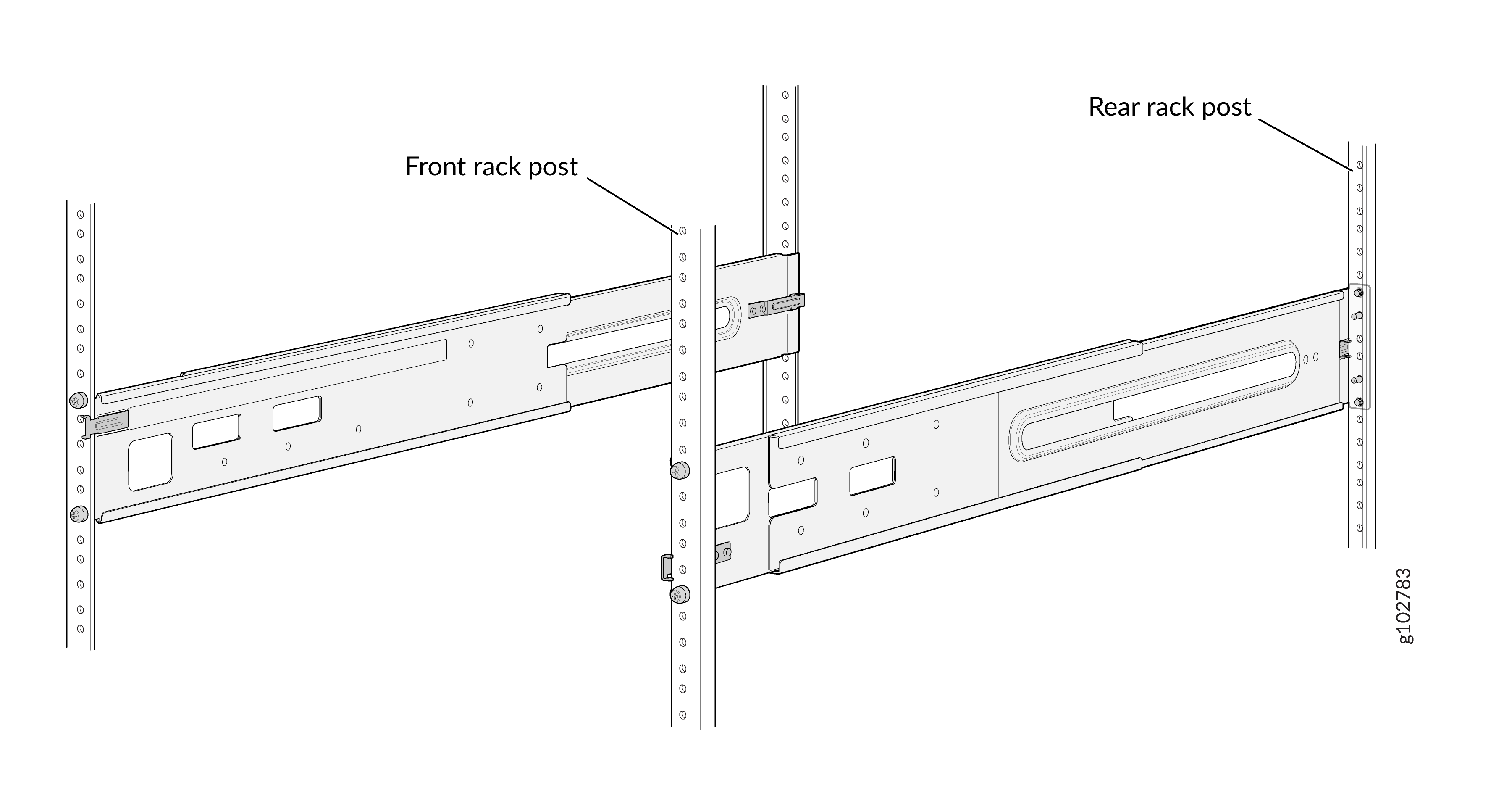
Figure 1: Remove the Guide Blocks from the Front Mounting Rails
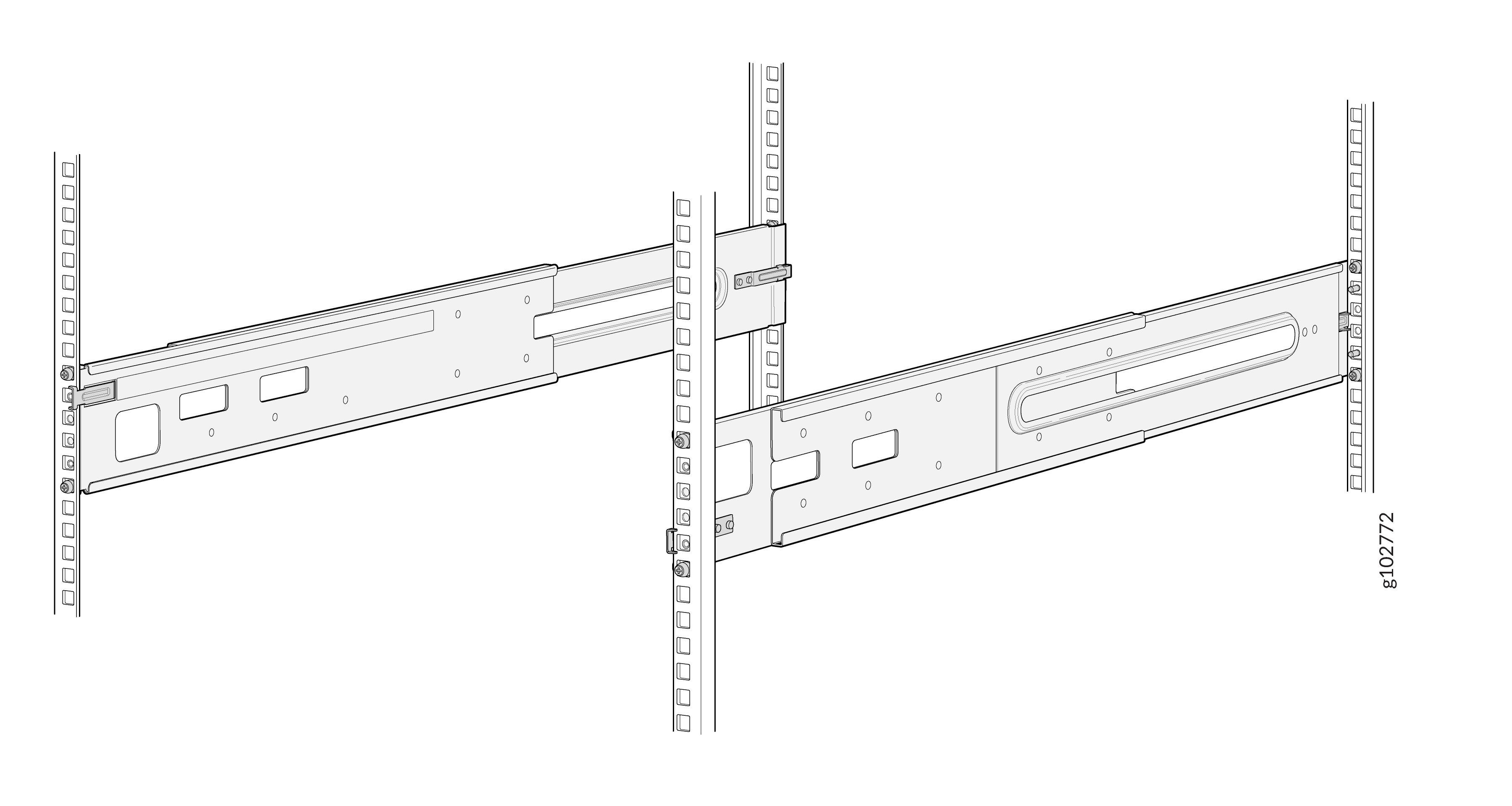
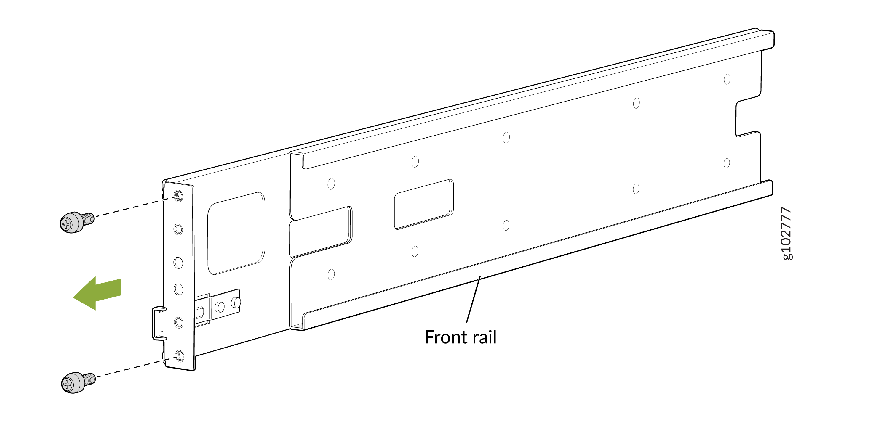 Figure 2: Remove the Guide Blocks from the Rear Mounting Rails
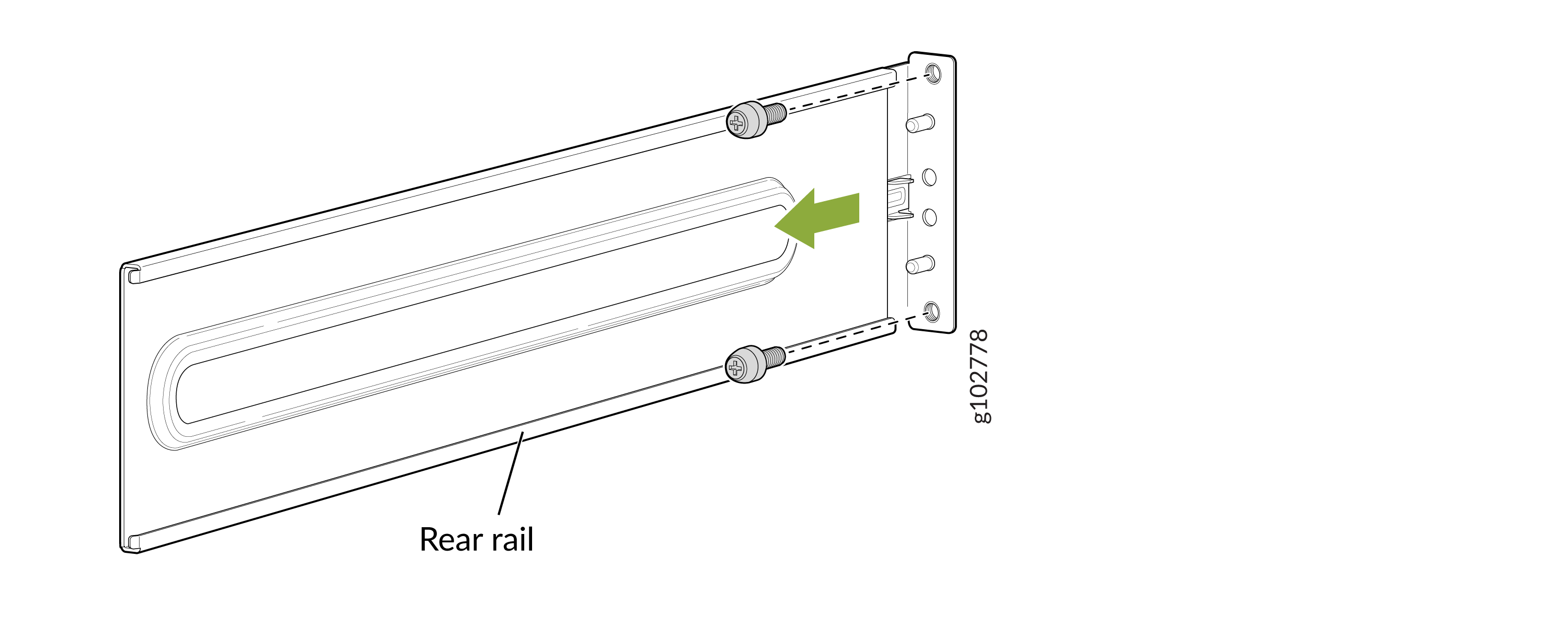
-
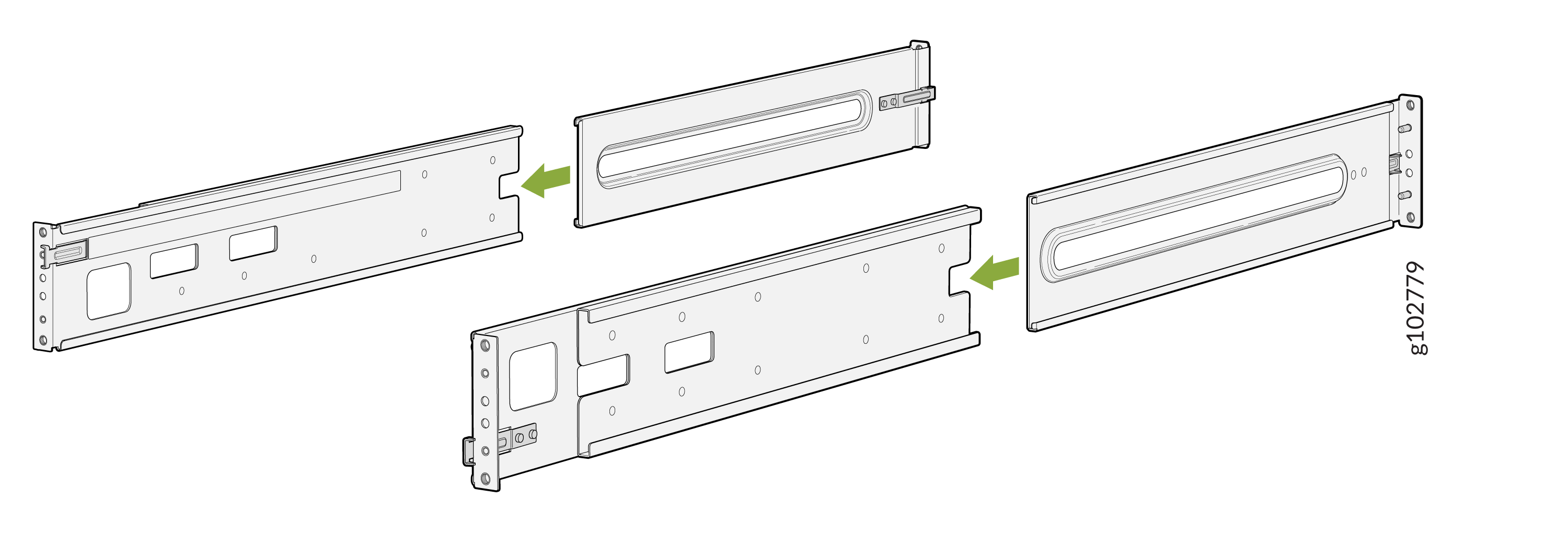
Assemble both the right and left mounting rails. Align the rear mounting
rails with the guides on the front mounting rails and gently slide the rear
mounting rails into the front mounting
rails.
-
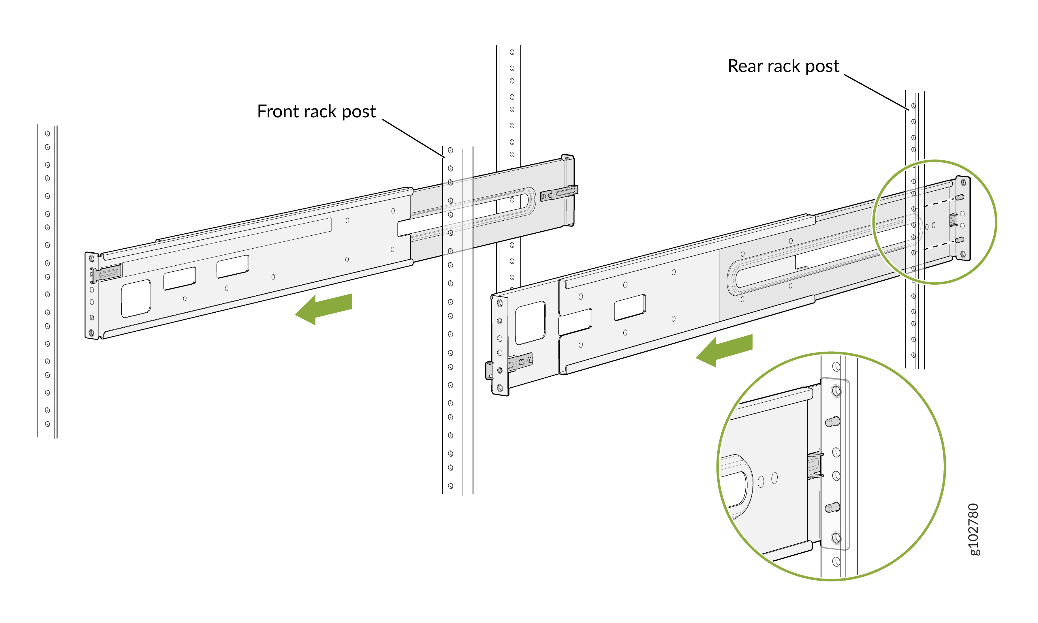
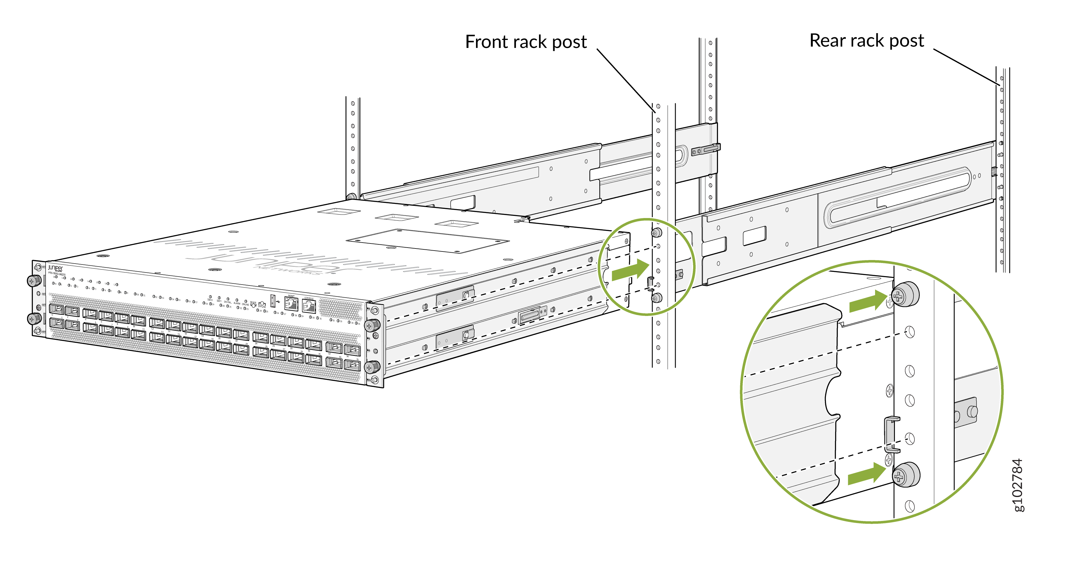
Insert the studs on the rear mounting rails in the holes on the rack
posts.
-
Attach the rear mounting rails to the rack posts—tighten the captive thumb
screws by using the
screwdriver.
-
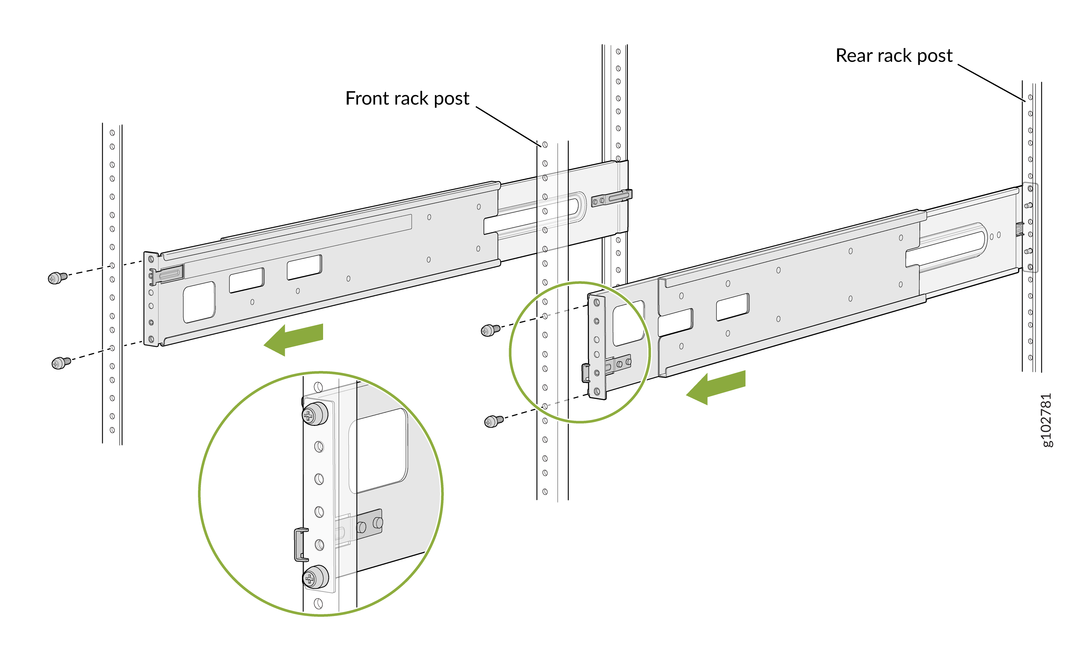
Attach the front mounting rails to the rack posts—tighten the thumb screws
by using the
screwdriver.
-
Ensure that the mounting rails are level by verifying that all screws on
one side of the rack align with the screws on the other
side.
-
Attach the mounting brackets to the router
chassis.
-
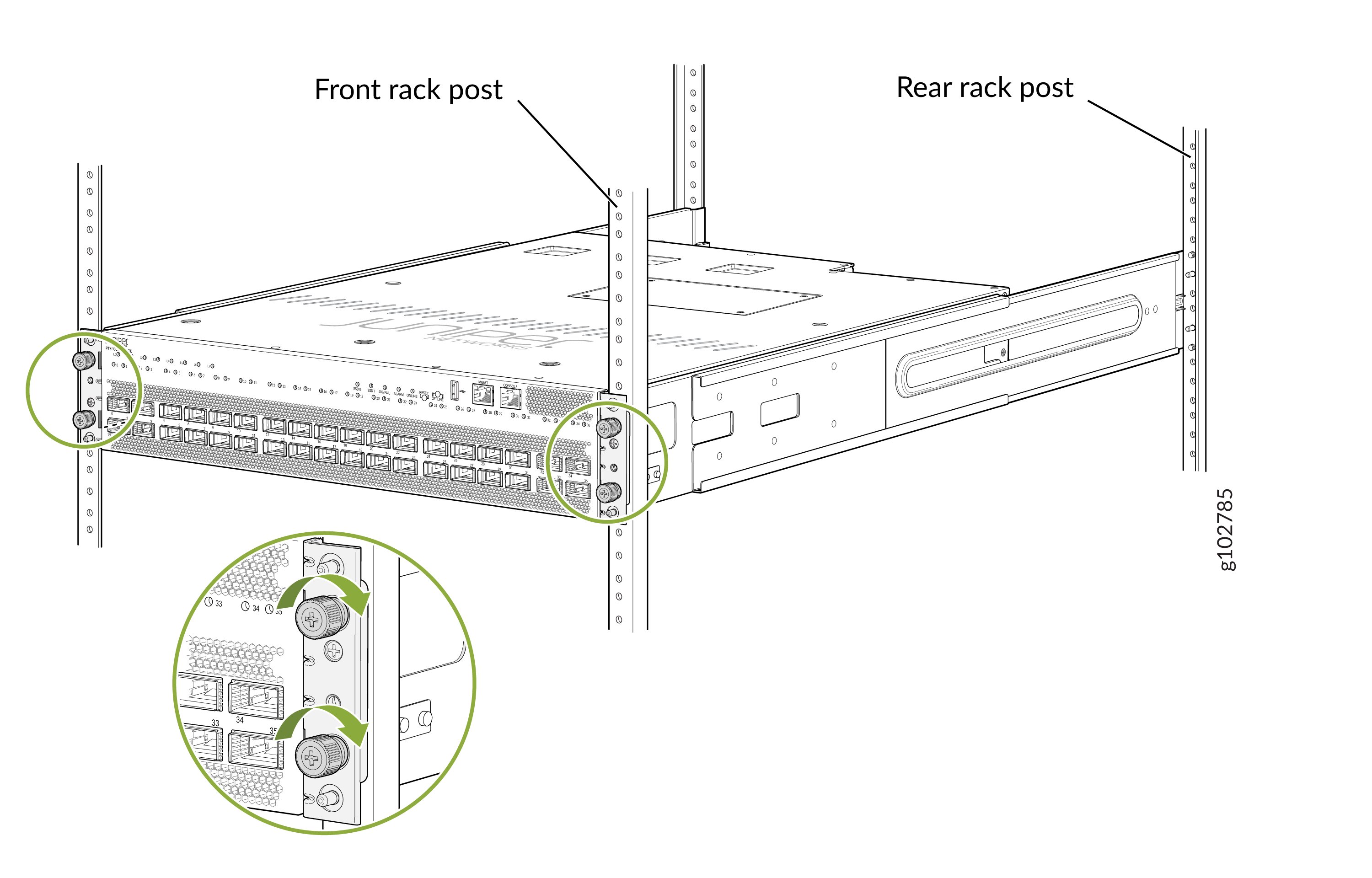
Align the mounting brackets with the guides on the mounting rails and
gently slide the chassis on to the mounting rails until the chassis locks in
place.
-
Secure the router to the rack—tighten the thumb screws by using the
screwdriver.
Mount the PTX10002-36QDD on Two Posts of a Rack or Cabinet
You can mount the router on:
-
Two posts of a 19-in. two-post rack or cabinet by using the two-post mounting kit (part number: JNP10002-2P-TL-RMK)—separately orderable
-
Four posts of a 19-in. four-post rack or cabinet by using the four-post mounting kit (part number: JNP10002-4P-TL-RMK)—provided
The remainder of this topic uses rack to mean rack or cabinet.
Before you mount the router on a two-post rack:
-
Verify that the site meets the requirements described in Site Preparation Checklist for PTX10002-36QDD Routers.
-
Place the rack in its permanent location, allowing adequate clearance for airflow and maintenance, and secure the rack to the building structure.
-
Read Safety Information, with particular attention to Chassis and Component Lifting Guidelines.
-
Ensure that you have taken the necessary precautions to prevent electrostatic discharge (ESD) damage (see Prevention of Electrostatic Discharge Damage).
-
Unpack the router from the shipping carton (see Unpack the Router).
Ensure that you have the following parts and tools available:
-
A number 2 Phillips (+) screwdriver—not provided
-
An ESD grounding strap—not provided
-
8 screws to secure the router to the posts of the pack—not provided
-
The two-post mounting kit that includes the following:
-
C-shaped two-post mounting brackets—2
-
L-shaped two-post mounting brackets—2
-
Screws to attach the two-post mounting brackets to the chassis—24
-
Have one person to support the weight of the router while another person secures the router to the rack posts.
To mount the router on a two-post rack:
-
Attach the two-post mounting brackets to the side panels of the router
chassis by using the screws to attach the brackets.
-
Align the front end of one of the C-shaped mounting brackets flush
with the front panel of the router
chassis.
-
Align the front end of one of the L-shaped mounting brackets behind
the C-shaped mounting
brackets.
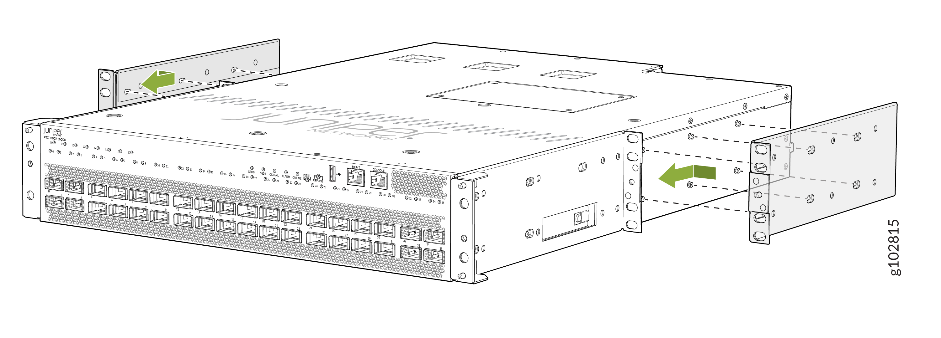 Figure 3: Router with the Brackets Attached
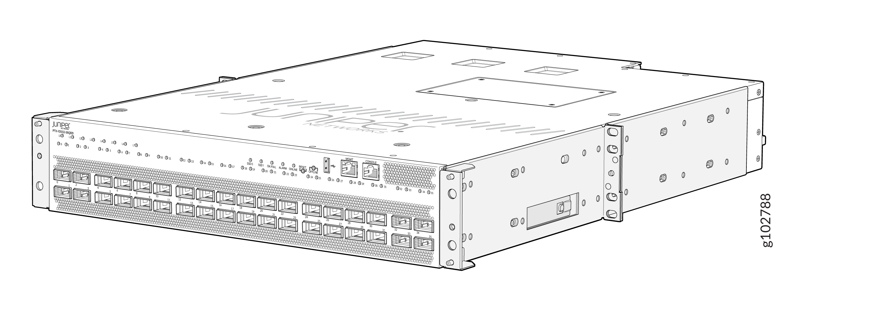
-
Align the front end of one of the C-shaped mounting brackets flush
with the front panel of the router
chassis.
-
Have one person grasp both sides of the router, lift the router, and
position it in the rack, aligning the holes of the C-shaped and L-shaped
mounting brackets with the threaded holes in the posts of the rack. Align
the bottom hole in both the mounting brackets with a hole in each rack post,
making sure that the chassis is
level.
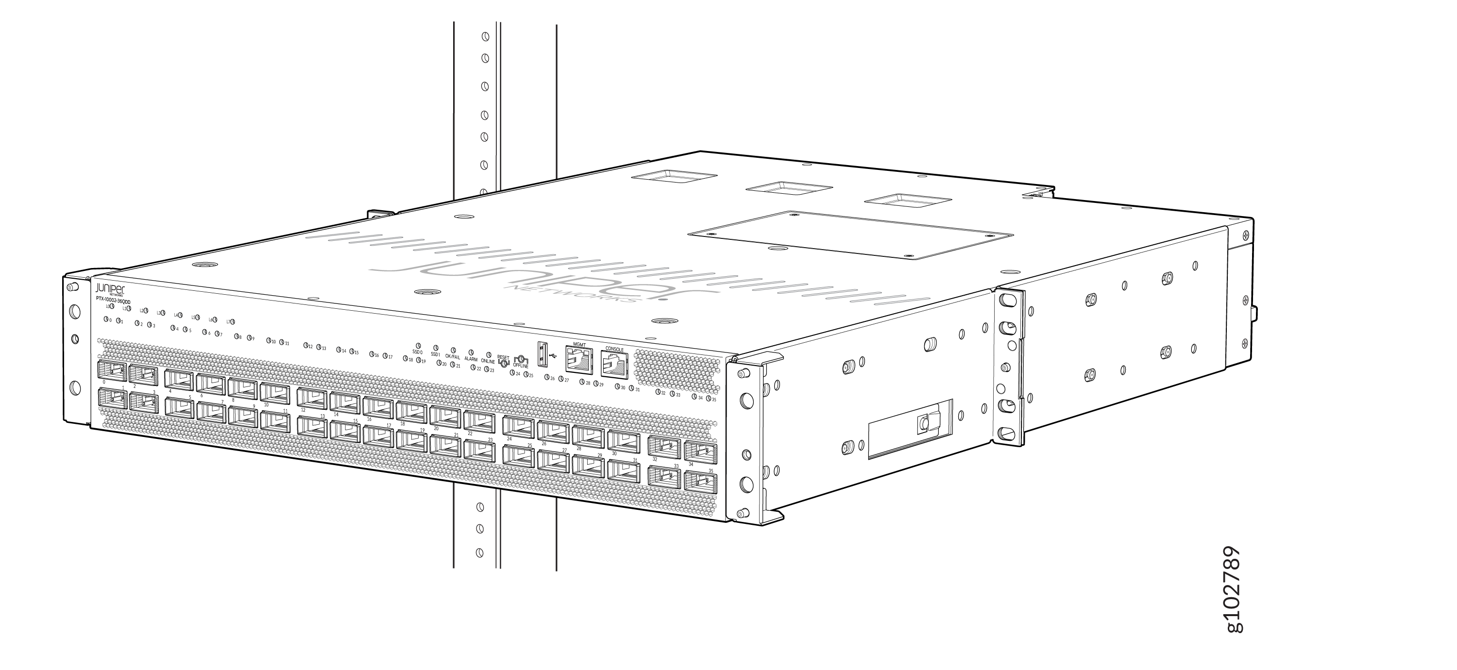
-
Secure the router to the posts of the rack. Have a second person attach the
mounting brackets to the rack by using the screws appropriate for your rack.
Tighten the screws by using a
screwdriver.