Unpack and Mount the PTX10001-36MR
Unpack the PTX10001-36MR
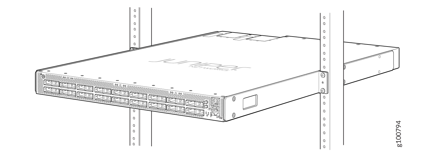
The PTX10001-36MR chassis is a rigid sheet-metal structure that houses the hardware components. The PTX10001-36MR is shipped in a cardboard carton, secured with foam packing material. The carton also contains an accessory kit and a pointer card with links to the quick start instructions.
PTX10001-36MR routers are maximally protected inside the shipping carton. Do not unpack the PTX10001-36MR until you are ready to begin installation.
To unpack a PTX10001-36MR:
Mount the PTX10001-36MR in a Rack or Cabinet
You can mount a PTX10001-36MR:
-
On four posts of a 19-in. rack or a 19-in. cabinet by using the mounting brackets provided with the device.
-
On two posts of a 19-in. rack or a 19-in. cabinet. A two-post rack mounting kit must be ordered separately.
For four-post rack installation, there are two front brackets and two rear brackets. This configuration allows either end of the device to be mounted flush with the rack and still be adjustable for racks with different depths. The minimum distance the front and rear rack rails can be spaced apart is 23.6 in. (60 cm) front to back. The maximum distance the front and rear rack rails can be spaced apart is 31.5 in. (80 cm) front to back. (The remainder of this topic uses rack to mean rack or cabinet.)
- Before You Begin Rack Installation
- Mount the PTX10001-36MR by Using the PTX-4PST-RMK-1U-E Rack Mount Kit (In a Square Slotted 4-Post Rack)
- Mount the PTX10001-36MR by Using the PTX-4PST-RMK-1U-E Rack Mount Kit (In a Threaded Hole 4-Post Rack)
- Mount the PTX10001-36MR by Using the JNP10001-4PST-RMK Rack Mount Kit
- Mount the PTX10001-36MR on Two Posts in a Rack
Before You Begin Rack Installation
Before you begin mounting a PTX10001-36MR in the rack:
If you are mounting multiple devices in a rack, mount the heaviest device at the bottom and mount the rest bottom to top in order of decreasing weight.
Mount the PTX10001-36MR by Using the PTX-4PST-RMK-1U-E Rack Mount Kit (In a Square Slotted 4-Post Rack)
Ensure that you have the following parts and tools available:
-
ESD grounding strap (not provided).
-
A pair of two piece mounting brackets. These mounting brackets attach to the front and rear rack posts.
-
A pair of mounting rails. These mounting rails are preinstalled on the PTX10001-36MR chassis with 16 Phillips M4 x 5 mm flathead screws.
-
Screwdriver appropriate for the mounting screws (not provided). A screwdriver is required, only if the mounting rails are not already installed.
To mount the PTX10001-36MR on four posts in a rack (square slotted 4-post rack) by using the PTX-4PST-RMK-1U-E rack mount kit:
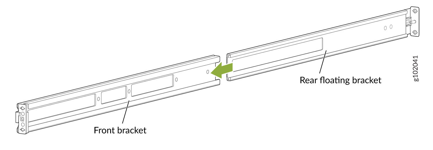
-
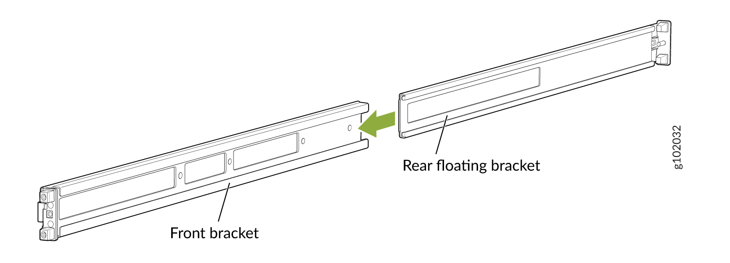
Assemble the mounting brackets. Slide the two brackets together. See
Figure 1.
Figure 1: Assemble the Mounting Brackets
-
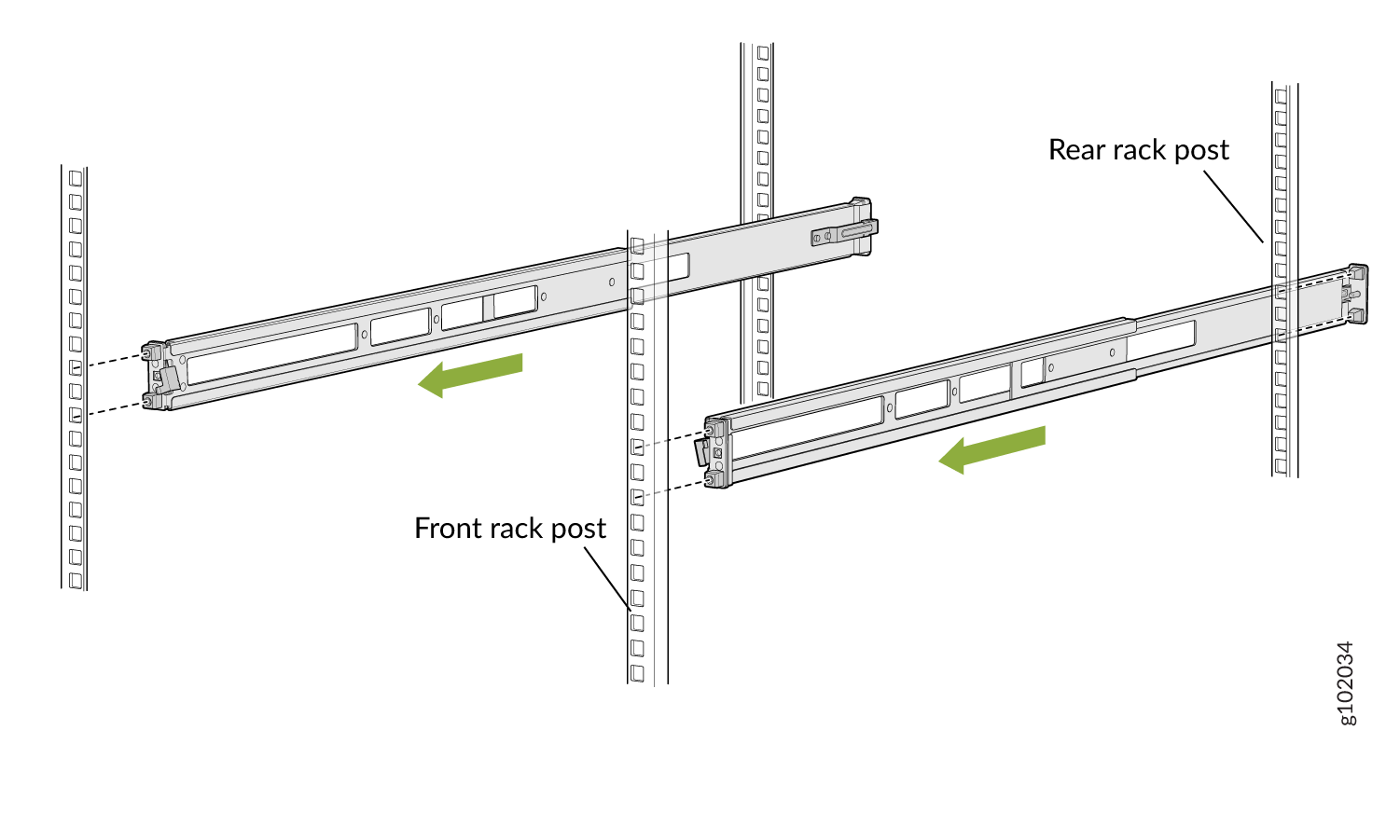
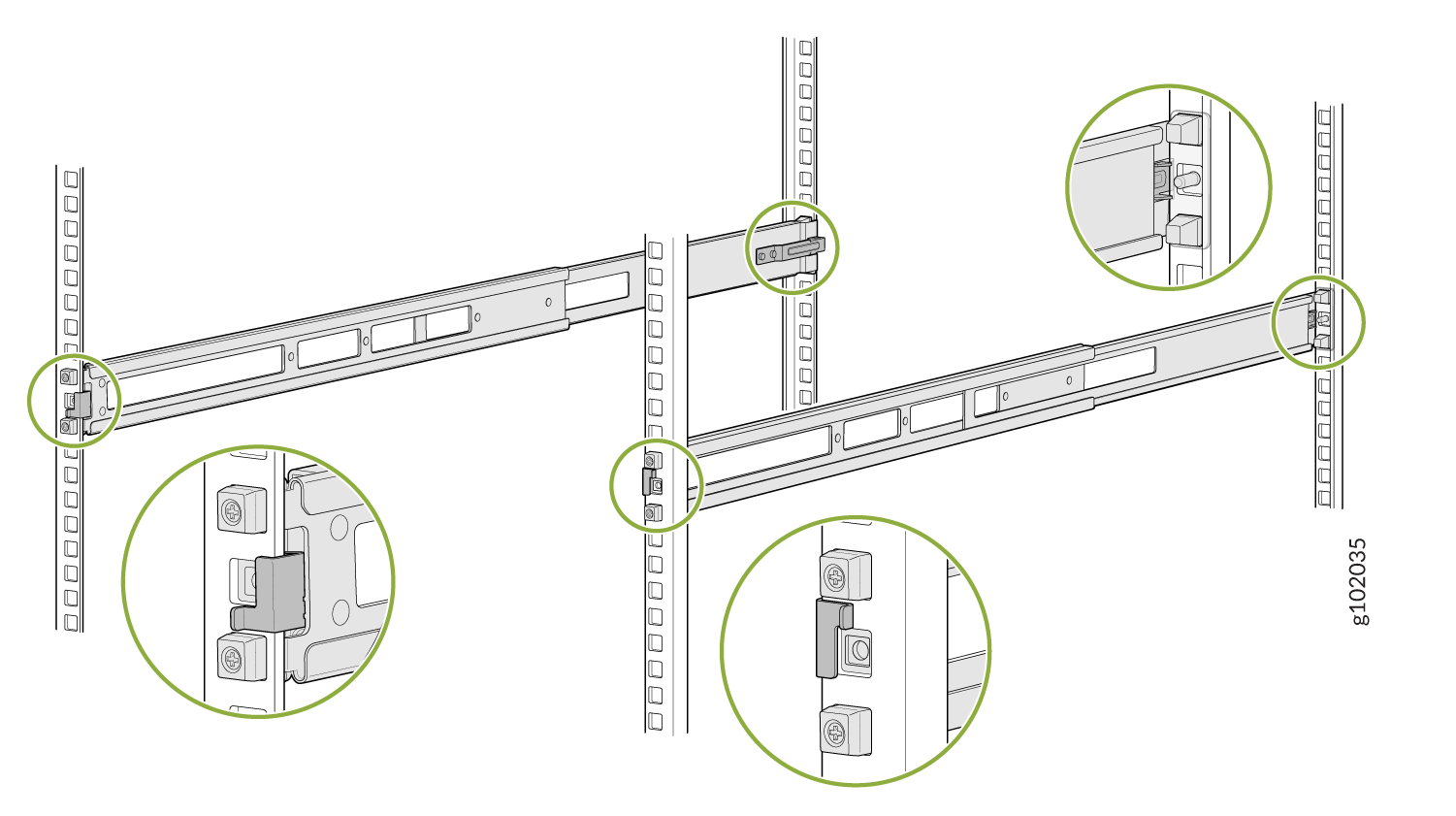
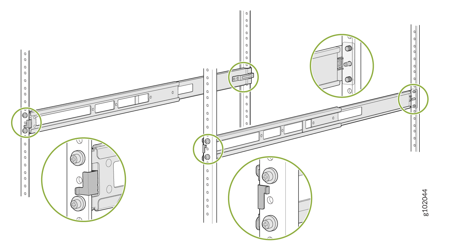
Attach the mounting brackets to the rack.
-
Standing in front of the rack, insert the rear floating
bracket's guide block into the rear rack post and slightly pull
on the rear floating bracket. You will hear a click sound,
indicating that the rear floating bracket is locked. See Figure 2.
Figure 2: Install the Rear Floating Brackets
-
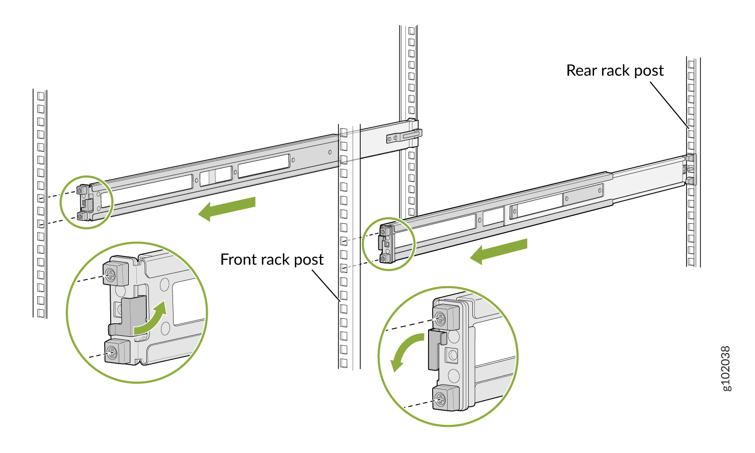
Move the latch lock on the front mounting bracket to the open
position, then insert the front mounting bracket's guide block
into the front rack post. See Figure 3
Figure 3: Install the Front Mounting Brackets
-
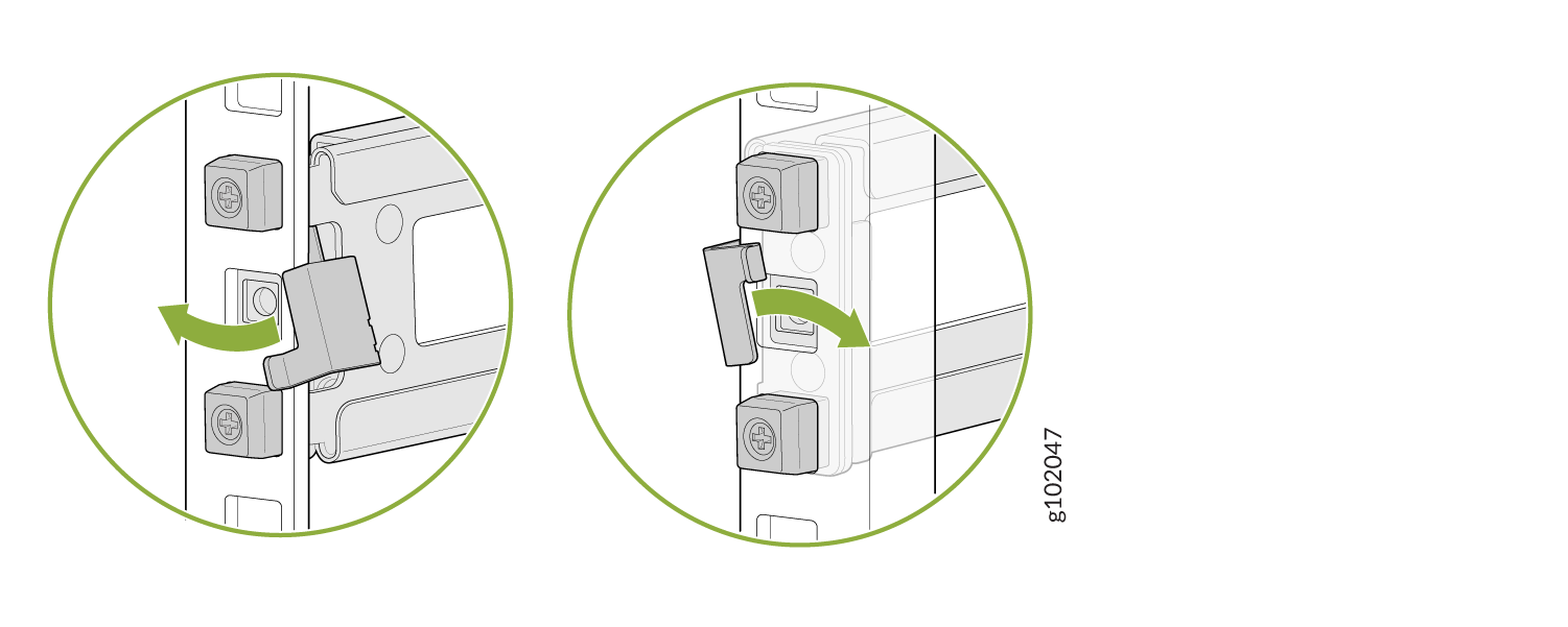
Push the lock latch over to the locked position. See Figure 4.
Figure 4: Front Mounting Bracket's Lock Latch
-
Visually ensure that the front and rear latches are locked into
place. See Figure 5
Figure 5: Mounting Brackets Locked
-
Standing in front of the rack, insert the rear floating
bracket's guide block into the rear rack post and slightly pull
on the rear floating bracket. You will hear a click sound,
indicating that the rear floating bracket is locked. See Figure 2.
-
If the mounting rails are already installed, skip to 6. If the mounting rails are not installed, perform
the following steps:
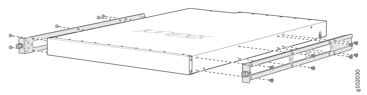
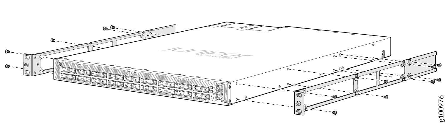
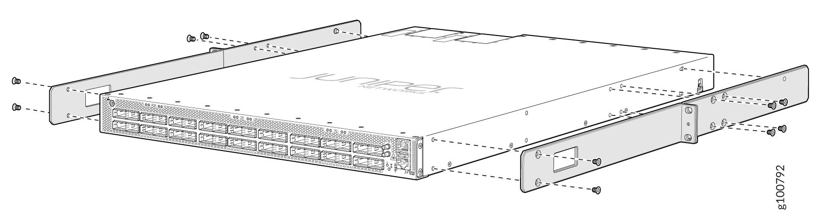
-
Align the holes in the mounting rail with the screw holes on
the side of the chassis. See Figure 6 to see the proper alignment for the
PTX10001-36MR.
Figure 6: Attach the Mounting Rails to the PTX10001-36MR
-
Align the holes in the mounting rail with the screw holes on
the side of the chassis. See Figure 6 to see the proper alignment for the
PTX10001-36MR.
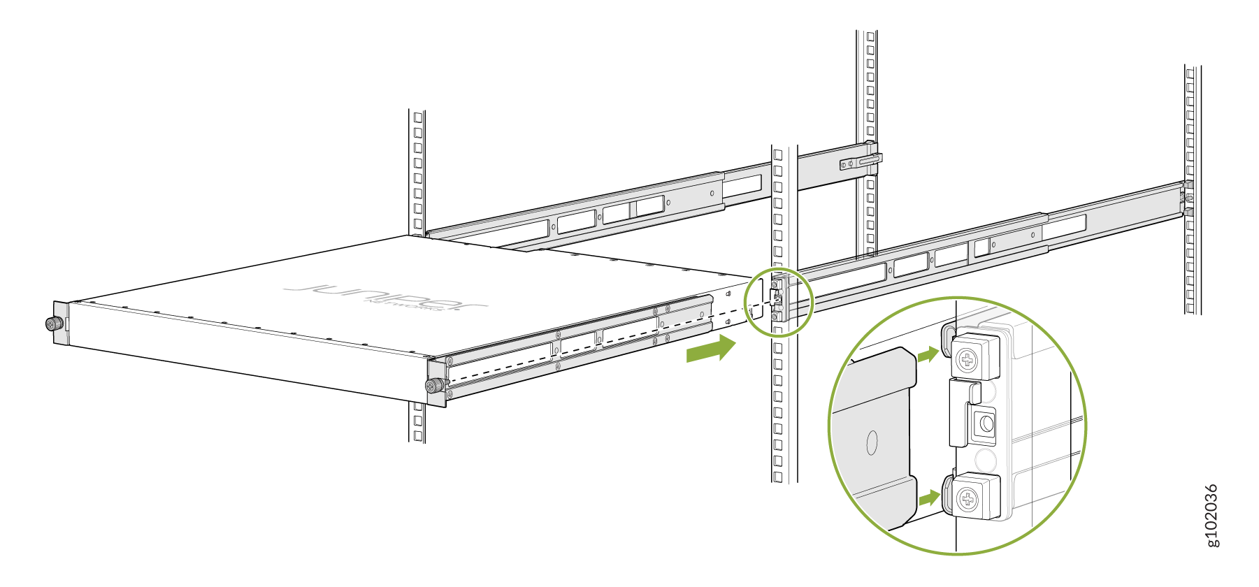
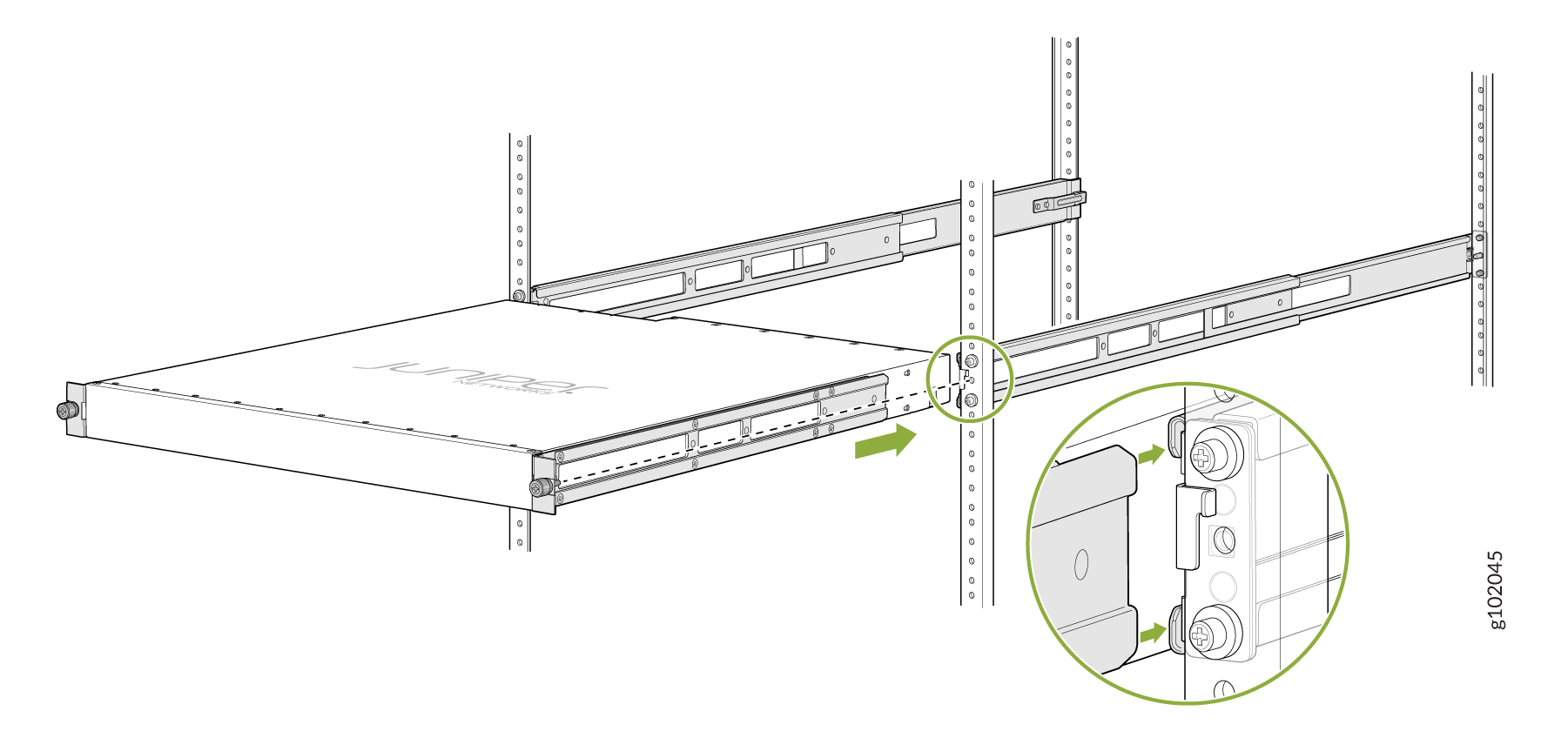
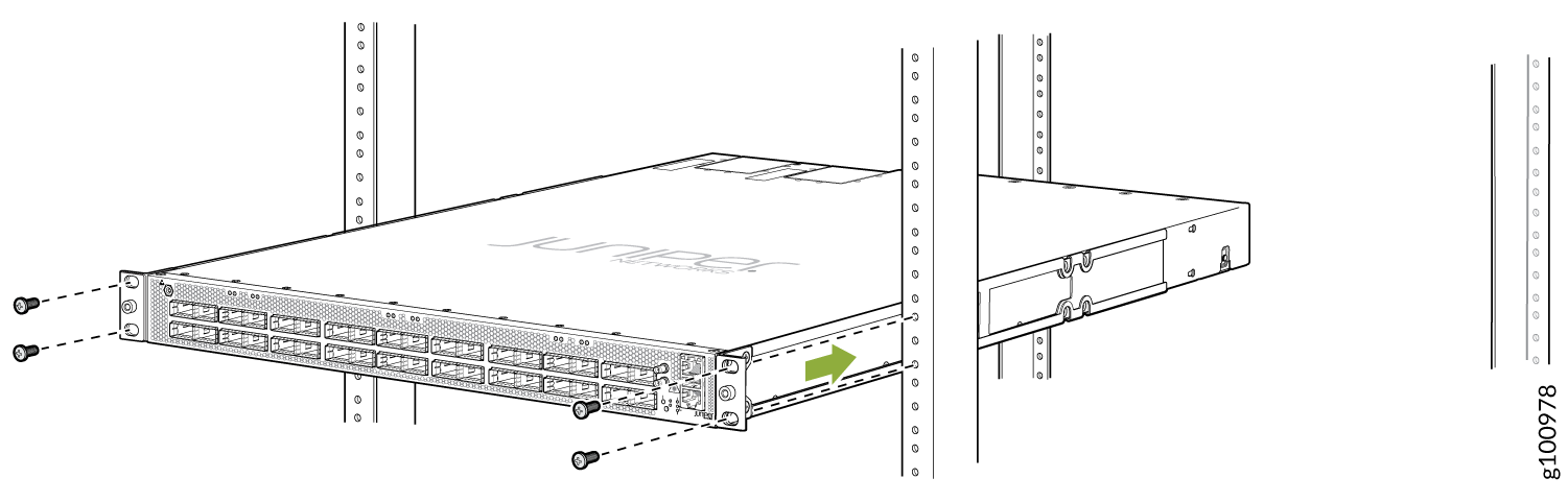
-
Grasp both sides of the device, lift it, and position the device so
that the mounting rails slide into the channel of the front mounting
brackets. See Figure 7.
Figure 7: Sliding the PTX10001-36MR into the Rack
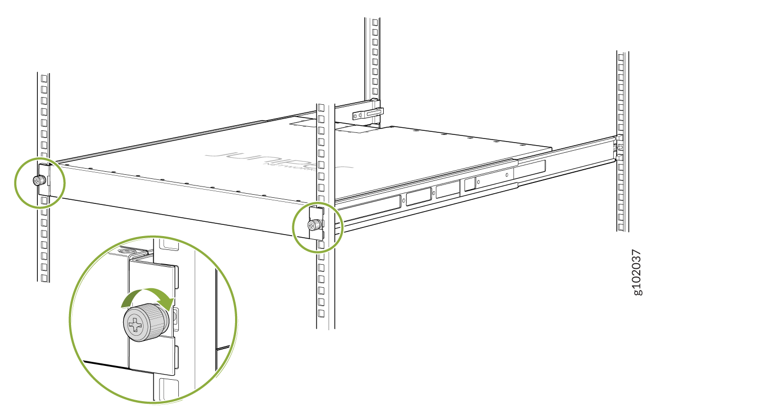
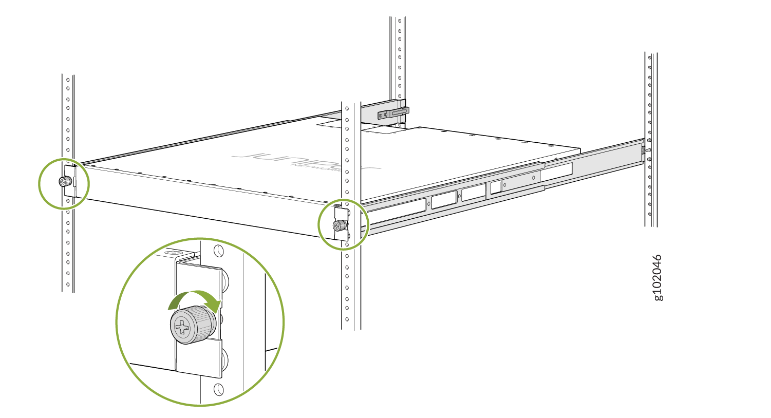
-
Tighten the thumb screws on the front of the mounting rails. See Figure 8.
Figure 8: Tighten Thumb Screws
Mount the PTX10001-36MR by Using the PTX-4PST-RMK-1U-E Rack Mount Kit (In a Threaded Hole 4-Post Rack)
Ensure that you have the following parts and tools available:
-
ESD grounding strap (not provided).
-
A pair of two piece mounting brackets. These mounting brackets attach to the front and rear rack posts.
-
A pair of mounting rails. These mounting rails are preinstalled on the PTX10001-36MR chassis with 16 Phillips M4 x 5 mm flathead screws.
-
Four rack mount screws appropriate for your rack, to secure the mounting brackets to the rack (not provided).
-
Screwdriver appropriate for the mounting screws (not provided).
To mount the PTX10001-36MR on four posts in a rack (threaded hole 4-post rack) by using the PTX-4PST-RMK-1U-E rack mount kit:
-
Remove the guide blocks from both mounting brackets by loosening the
screws. Place the guide blocks, screws, and washers to the side. See
Figure 9 and Figure 10.
Figure 9: Remove the Front Bracket's Guide Blocks
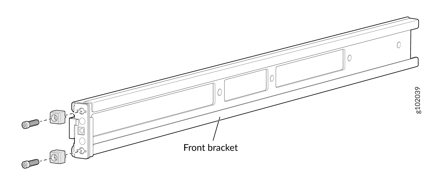 Figure 10: Remove the Rear Floating Bracket's Guide Blocks
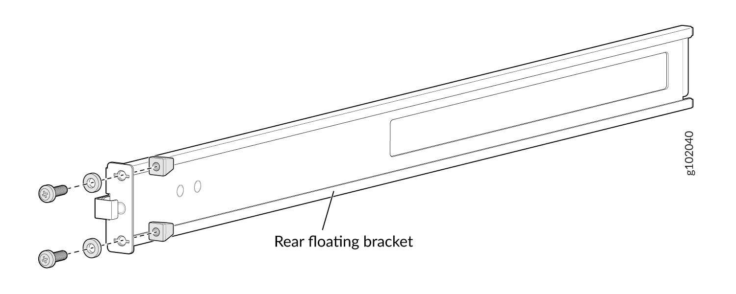
-
Assemble the mounting brackets. Slide the two brackets together. See
Figure 11.
Figure 11: Assemble the Mounting Brackets
-
Attach the mounting brackets to the rack.
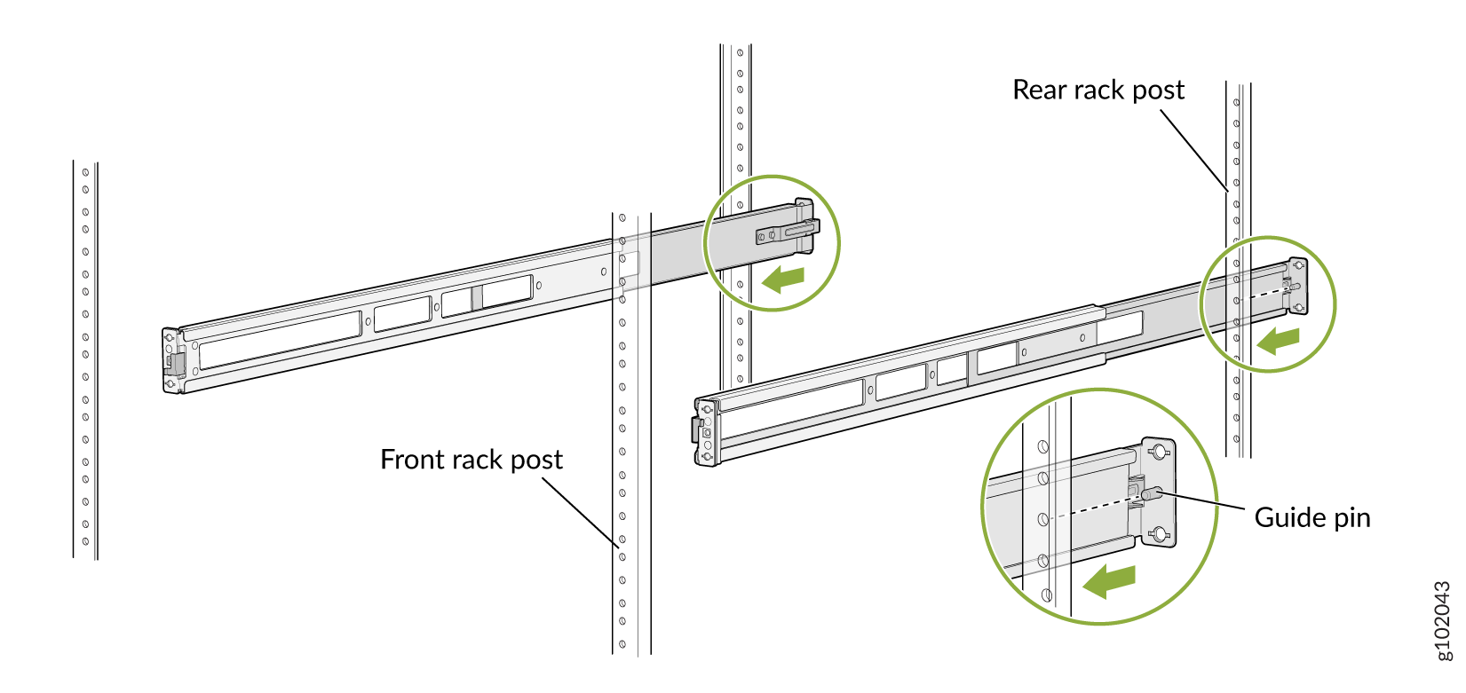
-
Standing in front of the rack, insert the rear floating bracket
into the rear rack post. Using the guide pin to align the
floating bracket, slightly pull on the rear floating bracket.
You will hear a click sound, indicating that the rear floating
bracket is locked. See Figure 12
Figure 12: Insert Rear Bracket
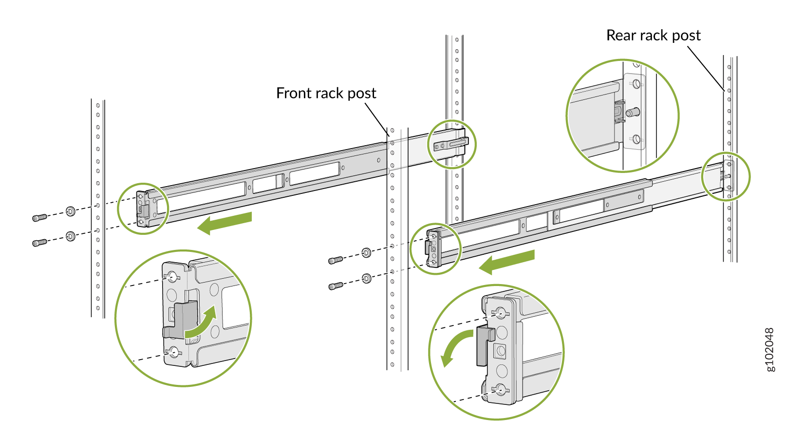
-
Move the latch lock on the front mounting bracket to the open
position. Align the holes of the front mounting bracket with the
holes of the front rack post. Using the screws removed from the
front brackets and the washers removed from the rear brackets in
3, secure the front mounting bracket to the
front rack post. See Figure 13.
Figure 13: Install Front Bracket
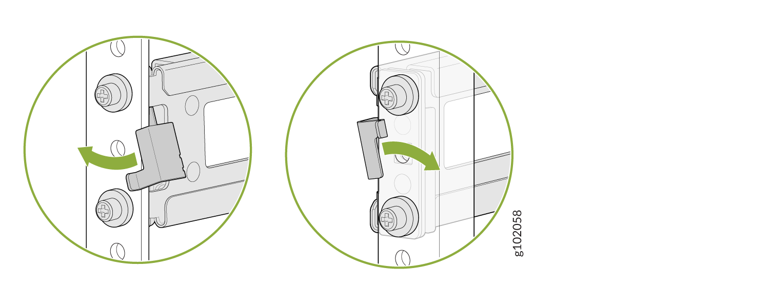
-
Push the lock latch over to the locked position. See Figure 14.
Figure 14: Front Mounting Bracket's Lock Latch
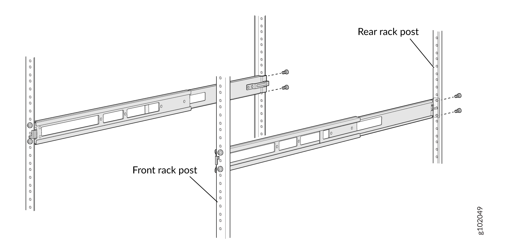
-
Using screws that are appropriate for your rack post, secure
the rear bracket to the rack post. See Figure 15.
Figure 15: Secure the Rear Floating Brackets
-
Visually ensure that the front and rear latches and screws are
secure. See Figure 16
Figure 16: Mounting Brackets Secured
-
Standing in front of the rack, insert the rear floating bracket
into the rear rack post. Using the guide pin to align the
floating bracket, slightly pull on the rear floating bracket.
You will hear a click sound, indicating that the rear floating
bracket is locked. See Figure 12
-
If the mounting rails are already installed, skip to 7. If the mounting rails are not installed, perform
the following steps:
-
Align the holes in the mounting rail with the screw holes on
the side of the chassis. See Figure 17 to see the proper alignment for the
PTX10001-36MR.
Figure 17: Attach the Mounting Rails to the PTX10001-36MR
-
Align the holes in the mounting rail with the screw holes on
the side of the chassis. See Figure 17 to see the proper alignment for the
PTX10001-36MR.
-
Grasp both sides of the device, lift it, and position the device so
that the mounting rails slide into the channel of the front mounting
brackets. See Figure 18.
Figure 18: Sliding the PTX10001-36MR into the Rack
-
Tighten the thumb screws on the front of the mounting rails. See Figure 19.
Figure 19: Tighten Thumb Screws
Mount the PTX10001-36MR by Using the JNP10001-4PST-RMK Rack Mount Kit
-
ESD grounding strap (not provided).
-
A pair of front mounting rails and rear mounting blades.
-
Sixteen flathead screws for the mounting brackets (Phillips, M4 x 6 mm)
-
Eight screws to secure the chassis and mounting blades to the rack (not provided).
-
Screwdriver appropriate for the rack-mounting screws (not provided).
To mount the PTX10001-36MR on four posts in a rack by using the JNP10001-4PST-RMK rack mount kit:
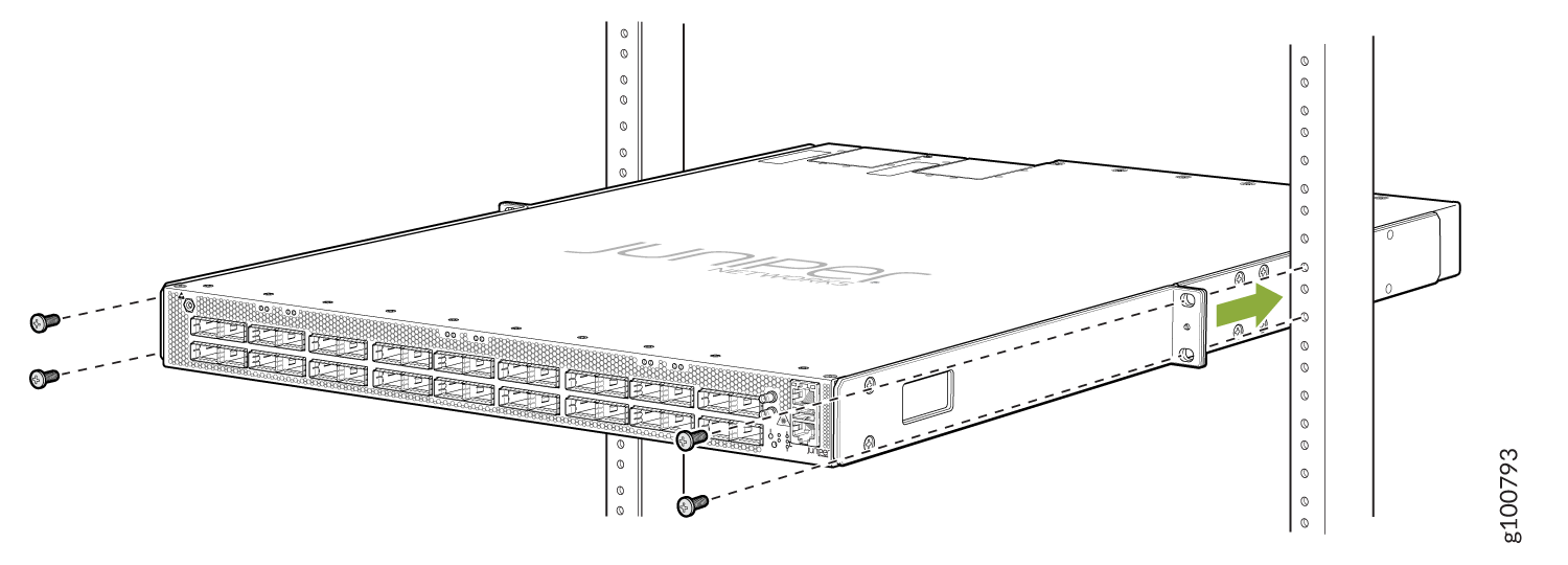
-
Align the holes in the mounting rail
with the screw holes on the side of the chassis. See Figure 20 to see the proper alignment
for the PTX10001-36MR.
Figure 20: Attach the Front Mounting Rails to the PTX10001-36MR
-
Have a second person secure the front of the device to
the rack by using 4 mounting screws (and cage nuts and washers if
your rack requires them). Tighten the screws. See Figure 21.
Figure 21: Attach the PTX10001-36MR to the Rack
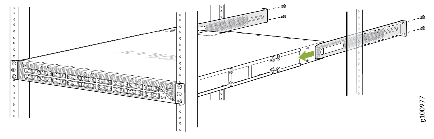
-
Continue to support the PTX10001-36MR while sliding the
rear mounting blades into the channel of the side mounting rails and
securing the blades to the rack. Use four mounting screws (and cage
nuts and washers if your rack requires them) to attach the blade to
the rack. Tighten the screws. See Figure 22.
Figure 22: Slide Mounting Blades into Mounting Rail
Mount the PTX10001-36MR on Two Posts in a Rack
-
ESD grounding strap (not provided).
-
A pair of mounting rails.
-
Screws to secure the mounting bracket to the chassis (12 screws are provided wit the 2-post rack mounting kit).
-
Four screws to secure the chassis and mounting bracket to the rack (not provided).
-
Screwdriver appropriate for the rack-mounting screws (not provided).
You can mount the PTX10001-36MR on two posts of a 19-in. rack (either a two-post or a four-post rack) by using a two-post rack-mounting kit (must be ordered separately).
To mount the PTX10001-36MR on two posts in a rack by using the two-post mounting kit that you purchased separately:
-
Align the hooks and the screw
holes on the mounting bracket with the screw holes on the side of
the chassis. See Figure 23 to see
the proper alignment for the PTX10001-36MR.
Figure 23: Attach the Two Post Mounting Brackets to the PTX10001-36MR
-
Have a second person secure the device to the rack by
using the appropriate mounting screws (and cage nuts and washers if
your rack requires them). Tighten the screws. See Figure 24.
Figure 24: Attach the PTX10001-36MR to a Two-Post Rack
-
Ensure that the device is level by verifying that all
the screws on one side of the rack are aligned with the screws on
the other side of the rack.
Figure 25: The PTX10001-36MR Secured in a Two-Post Rack