PTX10001-36MR Port Panel
PTX10001-36MR Port Panel Description
Operating in a fixed core router configuration, the PTX10001-36MR features flexible interface configuration options. The port panel has 24 double density quad small-form factor pluggable (QSFP56-DD) ports that support data rates of 10-Gbps, 25-Gbps, 40-Gbps, 100-Gbps, and 400-Gbps and 12 quad small form-factor pluggable (QSFP28) ports that support data rates of 10-Gbps, 25-Gbps, 40-Gbps, and 100-Gbps.
Figure 1 shows the PTX10001-36MR port panel.
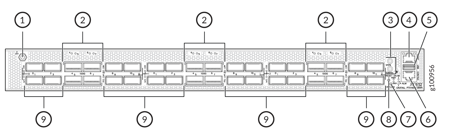
1 — ESD grounding point | 6 — RJ-45 console and time of day (TOD) port |
2 — 12 network ports—QSFP28 cages | 7 — Offline button. Pressing and holding this button for more than 4 seconds turns the device off. Pressing the button again turns the device back on. |
3 — Clock connectors (10 MHz and 1 PPS) | 8 — Reset button (do not use unless directed by JTAC) |
4 — RJ-45 management port (10 Mbps/100 Mbps/1000 Mbps) | 9 — 24 network ports—QSFP56-DD cages |
5 — USB port (USB 2.0 standard) |
- QSFP56-DD Network Ports
- QSFP28 Network Ports
- Port Numbering
- PTX10001-36MR Power Zone Restrictions
- How to Configure the QSFP28 Ports for 10-Gbps, 25-Gbps, and 40-Gbps Speeds
QSFP56-DD Network Ports
The PTX10001-36MR has 24 double density quad small-form factor pluggable (QSFP56-DD) sockets that are configured as 400GbE ports by default.
The QSFP56-DD network ports support:
-
QSFP56-DD transceivers
-
QSFP28-DD transceivers
-
QSFP28 transceivers
-
QSFP+ transceivers
-
Active optical cables (AOC)
-
Direct attach copper (DAC) cables
-
Direct attach copper break out (DACBO) cables
-
QSA adapters
Installing either the QDD-400G-LR8 or the QDD-400G-FR4 transceivers next to each other in ports 1, 3, 9, or 11 (on each logical PIC) is supported up to a maximum operating temperature of 35°C at an altitude of up to 6000 feet above sea level. For example, if you install either a QDD-400G-LR8 or a QDD-400G-FR4 transceiver in port 1 and port 3 of PIC 0, the maximum supported operating temperature and altitude combination is 35°C at 6000 feet above sea level. This restriction is due to thermal limitations.
Table 1 describes the maximum number of ports for each interface type supported by the QSFP56-DD ports.
|
Interface Type |
Maximum Supported Ports Note:
To achieve maximum ports, break out cables maybe required. |
|---|---|
|
400GbE |
24 |
|
100GbE |
96 |
|
40GbE |
24 |
|
25GbE |
192 |
|
10GbE |
96 |
Port speeds are configured using the set interfaces
interface-name speed speed
command.
You configure ports to operate at a particular speed by using the appropriate speed
option. If you configure a port to operate at a certain speed, and you want to return
the port to the default configuration, delete the speed statement from
the configuration at the [interfaces interface-name]
hierarchy level and commit the configuration. The network port is reset to the default
Ethernet interface.
See Port Speed on PTX10001-36MR Router Overview to learn about multiple port speeds supported on PTX10001-36MR router, guidelines, and how to configure the port speed.
QSFP28 Network Ports
The PTX10001-36MR has 12 quad small-form factor pluggable (QSFP28) sockets that are configured as 100GbE ports by default.
The QSFP28 network ports support:
-
QSFP28 transceivers
-
QSFP+ transceivers
-
Active optical cables (AOC)
-
Direct attach copper (DAC) cables
-
Direct attach copper break out (DACBO) cables
-
QSA adapters
Table 2 describes the maximum number of ports for each interface type supported by the QSFP28 ports.
|
Interface Type |
Maximum Supported Ports Note:
To achieve maximum ports, break out cables might be required. |
|---|---|
|
100GbE |
12 |
|
40GbE |
6 |
|
25GbE |
24 |
|
10GbE |
24 |
Port speeds are configured using the set interfaces interface-name
speed speed
command. You configure ports to
operate at a particular speed by using the appropriate speed option. If you
configure a port to operate at a certain speed, and you want to return the
port to the default configuration, delete the speed
statement from the configuration at the [interfaces
interface-name] hierarchy level and
commit the configuration. The network port is reset to the default Ethernet
interface.
See Port Speed on PTX10001-36MR Router Overview to learn about multiple port speeds supported on PTX10001-36MR router, guidelines, and how to configure the port speed.
Port Numbering
The interfaces for the PTX10001-36MR are divided into logical PICs and physical optical ports as follows:
-
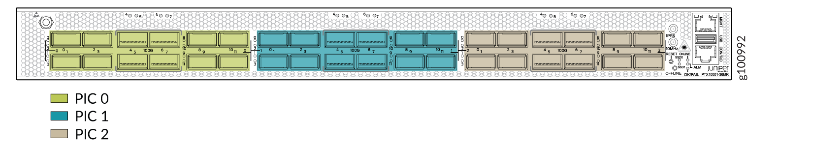
PICs: There are three logical PICs, numbered 0, 1, and 2 from left to right.
-
Ports: Each PIC controls 8 QSFP56-DD ports, numbered 0 through 3 and 8 through 11 from left to right. Each PIC also controls 4 QSFP28 ports numbered 4 through 7 from left to right.
Each PIC uses the same port numbering.
Figure 2 shows how the PTX10001-36MR network ports are divided into the 3 PICs.
PTX10001-36MR Power Zone Restrictions
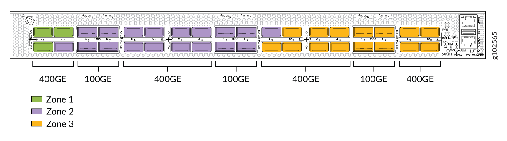
The ports on the PTX10001-36MR are organized in three power zones based on the power available to the ports in each zone. Table 3 describes the power zones, ports assigned to each zone, and the maximum power available to each zone. Figure 3 shows which ports belong to each power zone.
You cannot install an optic device that has more than 5 Watts of power in port numbers 4, 5, 6, or 7 (on each of the 3 logical PICs). If you do install an optic with more than 5 Watts of power in any of these ports, you will receive an error message.
|
Power Zone |
Ports assigned to the Power Zone |
Zone Maximum Power Limit |
|---|---|---|
|
1 |
0 through 2 (on PIC 0) |
50 Watts |
|
2 |
3 through 11 (on PIC 0) and 0 through 8 (on PIC 1) |
220 Watts |
|
3 |
9 through 11 (on PIC 1) and 0 through 11 (on PIC 2) |
220 Watts |
The total amount of power consumed by the optics inserted in the ports in each zone must not exceed the maximum power available to the power zone.
Power Zone 1 Limitations
Because of the limited power consumption capability of power zone 1, limitations are place on the number of optics that can be active in the power zone.
If the optics inserted into the ports in power zone 1 require more than 50 Watts of total power, one of the optics is shutoff by the software. The optic that is shutoff is based on the following:
-
If there are two optics active in the ports and a third optic is inserted into the third port, and the 50 Watts power limitation is exceeded, the last inserted optic is forced to shutdown and an alarm is triggered.
-
If three optics are inserted in the three ports while the device is shutdown, and the 50 Watts power limitation is exceeded, the optic in port 0/0/1 is forced to shutdown and an alarm is triggered.
-
If one of the optics is forced to shutdown due to the 50 Watts power limitation and then a different active optic is removed, the optic that was previously shutdown will be activated.
For information regarding using optic hardware with the PTX10001-36MR, see the Hardware Compatibility Tool.
How to Configure the QSFP28 Ports for 10-Gbps, 25-Gbps, and 40-Gbps Speeds
The QSFP28 ports support 10-Gbps, 25-Gbps, 40-Gbps, and 100-Gbps speeds. 100-Gbps is supported on all QSFP28 ports. 10-Gbps, 25-Gbps, and 40-Gbps speeds are not supported on all QSFP28 ports.
Further, when these supported QSFP28 ports are configuring for 10-Gbps, 25-Gbps, or 40-Gbps speeds, there are corresponding QSFP28 ports that must be configured as unused.
Table 4 lists the ports that support 10-Gbps, 25-Gbps, or 40-Gbps speeds and which must be configured as unused .
You must configure these ports as unused through the CLI. The PTX10001-36MR does not automatically power off the ports.
The list of ports supported in Table 4 correspond to 3 logical PICs. For example, for port number 4 listed in the table, there are actually three ports numbered 4 on the PTX10001-36MR (one on each logical PIC) and all three ports support the same speeds.
|
Port Speed |
Supported Port Number |
Corresponding Port Number that Must Be Configured as unused |
|---|---|---|
|
40 Gbps |
4 |
5 |
|
6 |
7 |
|
|
25 Gbps |
4 |
5 |
|
6 |
7 |
|
|
10 Gbps Note:
You can configure one of the ports (odd or even) for 1x10-Gbps and the other port (odd or even) for 1x100-Gbps at the same time. In this scenario, you do not need to configure any ports as unused. |
4 |
5 |
|
6 |
7 |
PTX10001-36MR Network Port LEDs
Each PTX10001-36MR network port uses a single bicolored LED to indicate link status, activity on the link, or a fault condition. The LEDs for the QSFP28 ports are located above the ports. The LEDs for the QSFP56-DD ports are located to the left of the ports. Figure 4 shows the location of the LEDs.
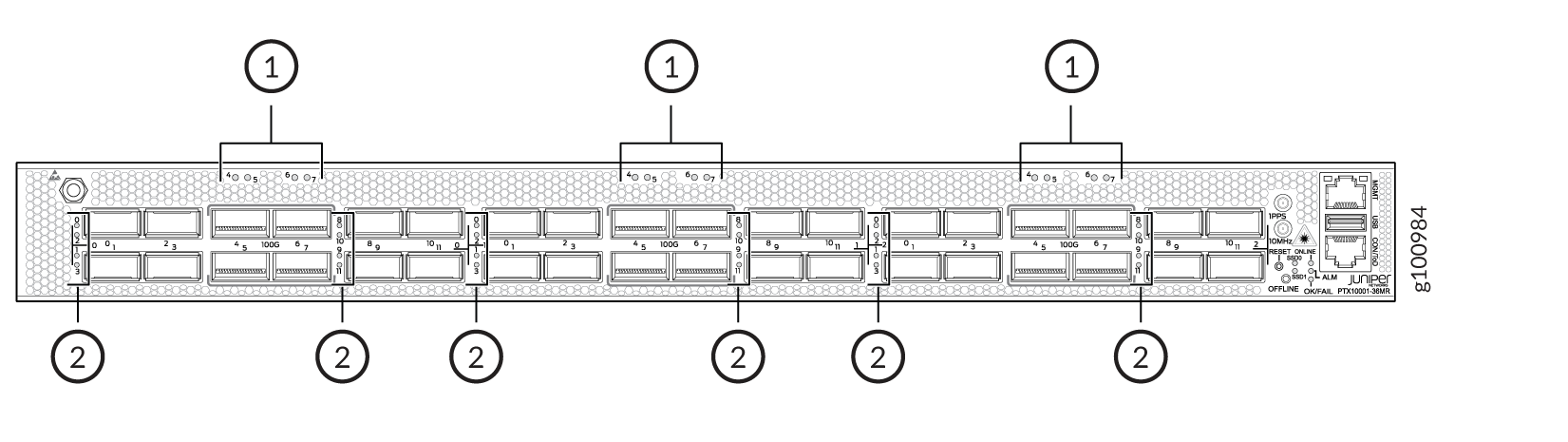
1 — 12 network ports—QSFP28 cages | 2 — 24 network ports—QSFP56-DD cages |
The number next to the LED indicates the port number that the LED belongs to. All 36 network port LEDs behave the same.
Table 5 describes the network port LEDs.
|
LED Color |
LED State |
Description |
|---|---|---|
|
Unlit |
Off |
The port is administratively disabled, there is no power, the link is down, or a transceiver is not present. |
|
Green |
On steadily |
A link is established and all channels are up. |
|
Blinking |
The beacon function is enabled on the port. |
|
|
Amber |
On steadily |
One or more channels are up. At least one channel has activity, but not all connections are active. |
|
Blinking |
The beacon function is enabled on the port. |
|
|
Red |
On steadily |
All channels are down. |
|
Blinking |
The beacon function is enabled on the port. |