PTX10001-36MR Management Panel
The management panel allows you to have a management channel into the device that is separate from production traffic.
PTX10001-36MR Management Panel Description
The PTX10001-36MR management panel is located to the right of the network ports. Figure 1 shows the connections and components of the management panel and the network ports.
You manage the PTX10001-36MR by using the Junos OS Evolved CLI, which is accessible through the console and out-of-band management ports on the management panel. In addition, the management panel has system status LEDs that alert you to minor or major alarms or other issues with the router, SSD status LEDs, external clock synchronization ports, and a USB port to support software installation and recovery.
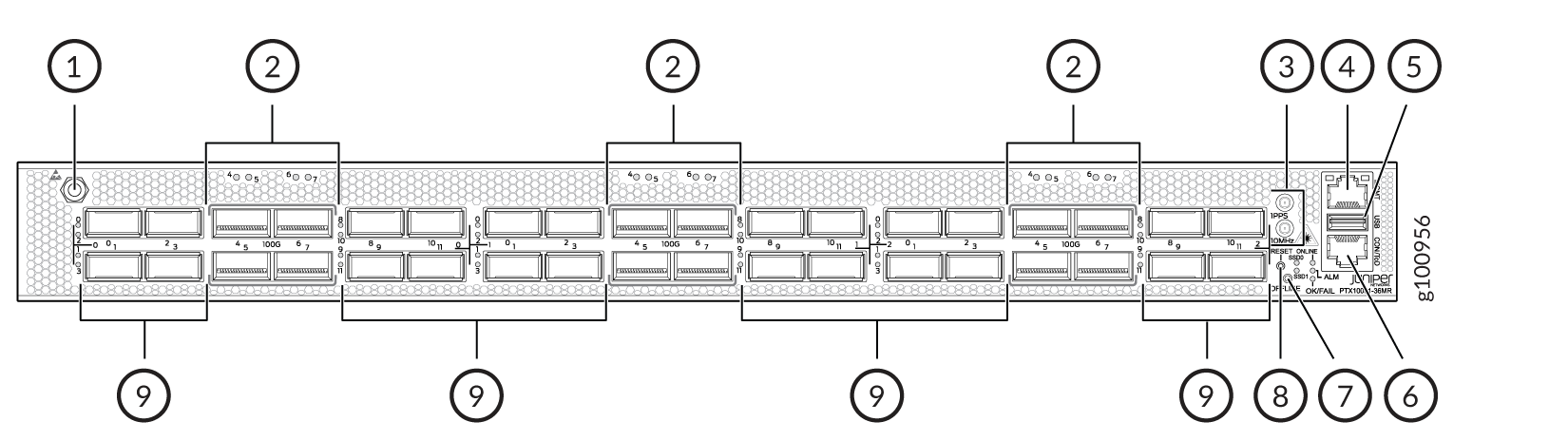
1 — ESD grounding point | 6 — RJ-45 console and time of day (TOD) port |
2 — 12 network ports—QSFP28 cages | 7 — Offline button. Pressing and holding this button for more than 4 seconds turns the device off. Pressing the button again turns the device back on. |
3 — Clock connectors (10 MHz and 1 PPS) | 8 — Reset button (do not use unless directed by JTAC) |
4 — RJ-45 management port (10 Mbps/100 Mbps/1000 Mbps) | 9 — 24 network ports—QSFP56-DD cages |
5 — USB port (USB 2.0 standard) |
PTX10001-36MR Management Panel LEDs
The following status LEDs ae located on the management panel:
-
SSD Port LEDs
-
Chassis status LEDs
-
Management Port LEDs
Figure 2 shows the locations of the SSD and status LEDs.
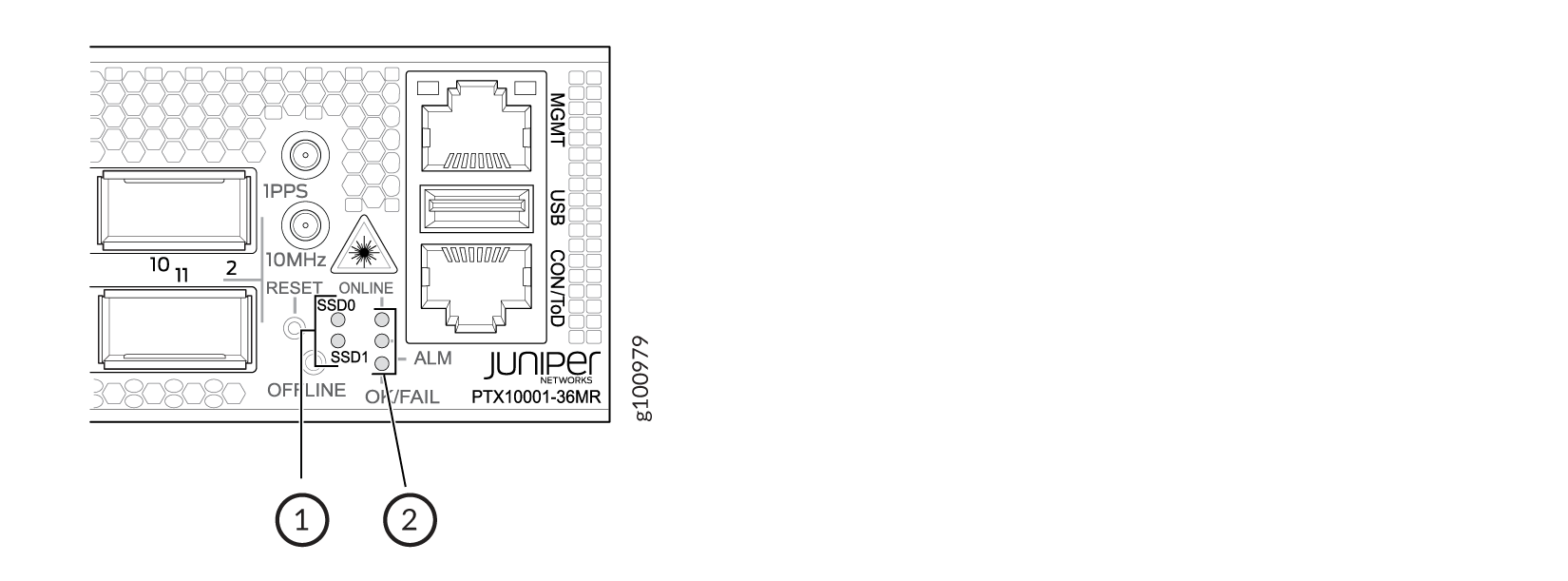
1 — SSD port LEDs | 2 — Status LEDs |
The following sections explain how to interpret these LEDs.
PTX10001-36MR SSD Port LEDs
The PTX10001-36MR has two 200-GB Serial Advanced Technology Attachment (SATA) solid-state drives (SSD). Each SSD has its own status LED. The LEDs are located on the management panel next to the chassis status LEDs. The LEDs are labeled SSD0 and SSD1.
Table 1 describes the SSD status LEDs.
|
LED |
Color |
State |
Description |
|---|---|---|---|
|
SSD0 and SSD1 |
Unlit |
Off |
The SSD is not being accessed. |
|
Green |
Blinking |
The SSD is active and being accessed. |
PTX10001-36MR Chassis Status LEDs
The PTX10001-36MR has three LEDs that indicate system status. They are located in the middle of the management panel (see Figure 2).
Table 2 describes the chassis status LEDs on a PTX10001-36MR, their colors and states, and the status that they indicate.
|
Name |
Color |
State |
Description |
|---|---|---|---|
|
ONLINE |
Unlit |
Off |
The device is powered off. |
|
Green |
On steadily |
Junos OS Evolved is loaded on the device. |
|
|
Green |
Blinking |
Junos OS Evolved is being loaded on the device. |
|
|
ALM (Alarm) |
Unlit |
Off |
The device is halted or there is no alarm. |
|
Red |
On steadily |
A major hardware fault has occurred, such as a temperature alarm or power failure, and the device has halted. Power off the device by setting the AC power source outlet to the OFF (O) position, or unplugging the AC power cords. Correct any voltage or site temperature issues, and allow the device to cool down. Power on the device and monitor the power supply and fan LEDs to help determine where the error is occurring. |
|
|
Yellow |
On steadily |
A minor alarm has occurred, such as a software error. Power off the device by setting the AC power source outlet to the OFF (O) position, or unplugging the AC power cords. Power on the device and monitor the status LEDs to ensure that Junos OS Evolved boots properly. |
|
|
Yellow |
Blinking |
Both a major and a minor alarm is occurring on the device. |
|
|
OK/FAIL |
Green |
On steadily |
There are no fault conditions on the device. |
|
Red |
Blinking |
A fault has occurred on the device. |
PTX10001-36MR Management Port LEDs
There is one management port on the PTX10001-36MR that has LEDs that indicate link status and link activity. The port is located on the management panel above the USB port and is labeled MGMT. The management port has separate LEDs for status and activity. Figure 3 shows the location of the LEDs.
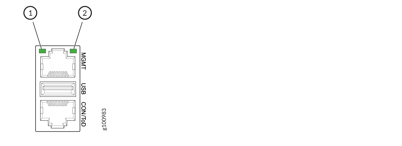
1 — Status LED (RJ-45) | 2 — Link activity LED (RJ-45) |
Table 3 describes the RJ-45 management port LEDs.
|
LED |
Color |
State |
Description |
|---|---|---|---|
|
Status |
Unlit |
Off |
No link is established or the port speed is 10 Mbps. |
|
Yellow |
On steadily |
The port speed is 100 Mbps. |
|
|
Green |
On steadily |
The port speed is 1 Gbps. |
|
|
Link activity |
Green |
Blinking |
A link is established and there is link activity. |